Materials Processing
Microstructure and Oxidation Behavior of Pt and Pt–Ir Diffusion Coatings on Ni-Based Single Crystal Superalloy
2020 Volume 61 Issue 8 Pages 1671-1678

Details
2020 Volume 61 Issue 8 Pages 1671-1678
The effects of Ir addition and coating method on the microstructure and oxidation behavior of Pt–xIr (x = 0–30 at%) diffusion coatings were investigated. A nickel-based single crystal superalloy UCSX-8 was used as a substrate material, while the coatings were developed by either an electroplating or a paste coating method followed by an annealing heat treatment. The phase identification and microstructure analyses by XRD and SEM/EDS revealed that the alloying of Ir in Pt diffusion coating resulted in the formation of L10 ordered α-NiPt2Al structure. Cyclic oxidation tests were carried out at 1423 K in still air in order to investigate the thermal stability and oxidation behavior of the coatings. It was found that Ir can significantly retard the formation of voids in both the coating and substrate. In addition, by replacing electroplating method to the paste coating method, the crack problem due to the brittle feature of electroplated Pt–Ir coatings could be solved. Therefore, the Pt–20Ir diffusion coating prepared by the paste-coating method is promising as the bond-coating material due to formation of less voids, no crack and stable Al2O3 on the surface.
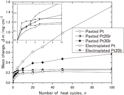
Fig. 5 Oxidation kinetic curve of the specimens during cyclic oxidation test at 1423 K.
Ni-based single crystal superalloys with good high temperature strength and creep resistance can be used in the hottest section of gas turbines such as turbine blades. In addition, for further protection against oxidation and hot corrosion, thermal barrier coating (TBC) systems were developed.1–4) Basically, TBCs contain a ceramic top coat (TC) which provides thermal insulation, a metallic bond coat (BC) and a thermally grown oxide (TGO) between the TC and the BC. The BC, known as an Al-enriched layer not only supports the bonding between the TC and a substrate material but also works as an Al reservoir to form a TGO layer during high temperature exposure. The TGO which consists mainly of α-alumina can prevent oxidation of the BC and the substrate. One of the good candidates for a bond-coat can be a Pt-modified aluminide coating or an MCrAlY-type overlay coating; however, the transformation from a β-(Al,Pt)Ni phase to γ′-(Ni,Pt)3Al, and the formation of brittle Topologically Close-Packed (TCP) structure in the coating and substrate during long-term service may lead to degradation of the coating structure.5) Recently, a Pt diffusion coating with the γ-γ′ microstructure, which is similar to that of the substrate has been proposed.6–9) It has been reported to reduce rumpling7,10,11) and suppress the precipitation of brittle TCP phases.10)
In order to further improve the working efficiency of turbine engines and to reduce CO2 emission, application of platinum group metal (PGM) elements such as palladium,12) ruthenium, rhodium or iridium13) to oxidation resistant coatings seems promising, due to their chemical stabilities. Among PGMs, iridium exhibits the highest melting temperature (2716 K), high tensile strength (440 MPa) at room temperature, excellent chemical stability and lower diffusivity into Ni-based alloys than Pt.14) As a result, it can be expected that the addition of Ir into Pt diffusion coating may result in better thermal properties and prolong the life of coated materials. Above them as backgrounds, the authors’ research group has investigated Pt–Ir-modified aluminide coatings and reported that Ir addition can improve the high temperature oxidation resistance of the Pt-modified aluminides.15–17) Then the next step is to further improve the oxidation resistance of Pt diffusion coating by the Ir addition.
In this study, the microstructure and oxidation resistance of Pt–Ir diffusion on a single crystal Ni-based superalloy were investigated. In fact, Yasui et al. reported that by the electrodeposition process, addition of Ir to Pt-diffusion coating suppresses the formation of voids in the substrate but oxidation resistance of the coating is dependent on the quality of Pt–Ir films deposited, which is affected by substrate surface finishing and composition.18) To minimize this problem, a new route to fabricate Pt and Pt–Ir coating, i.e., a paste coating, was introduced in comparison with the electroplating method. The phase transformation and cyclic oxidation behaviors of the Pt and Pt–Ir coatings at 1423 K by both paste and electroplating methods were discussed.
A so-called 4th generation Ni-based single crystal superalloy UCSX-8 was used as the substrate material, and its nominal composition is Ni–6.4Co–1.8Cr–3.6Mo–4.1W–5.2Re–2.1Ru–6.8Al–10.0Ta (mass%). The substrate material, supplied as a ⟨100⟩ oriented single-crystal bar was in a diameter of 10 mm with the typical γ + γ′ microstructure after solution and aging heat treatments. The bar-shaped substrate was then cut into discs with the thickness of 2 mm, mechanically polished with SiC paper up to #800 and degreased with acetone for 5 minutes in an ultrasonic bath.
The Pt and Pt–Ir films were deposited on the surface of specimens by two methods: electroplating and paste coating. For electroplating of Pt and Pt–20Ir films (8 µm in thickness), surface of the specimens was grit blasted with Al2O3 powder and then ultrasonically cleaned in acetone. With the surface roughness of 0.5–0.7 µm, the specimens were then cleaned in NaOH (1 mol/L) solution at 323–333 K for 1 minute and with 5 V DC in HCl (1 mol/L) for 30 seconds to thoroughly remove the oxide on the surface. The electroplated conditions are listed in Table 1. As for the Pt–20Ir film, in order to enhance adhesion of the coating to the substrate material and to reduce cracking problem probably due to H2 gas generation during the electroplating process, a 2 µm thick Pt film was electroplated on the surface in advance as a bonding layer. The electroplating parameters were identical to Pt coating. A 6 µm thick Pt–20Ir film was subsequently electroplated on the Pt layer, and the electroplating condition is given in Table 2. All the specimens with 8 µm thick Pt and 2 µm Pt/6 µm thick Pt–20Ir were diffusion heat treated for 1 hour at 1373 K in flowing Ar to protect coatings from oxidation. For the Pt and Pt–Ir coatings by paste method, the coatings were deposited on the as-polished surface of the substrate with #800 SiC paper. The Pt and Pt–xIr (x = 0–30 at%) powder with mean diameter about 500 nm was mixed with volatile resin supported to form a paste type and then coated on the surface of specimens by simple spray method. The thickness of coatings was controlled to about 10 µm by numbers of cycle spray and dry processes. The as-coated specimens were subsequently heat treated at 773 K for 2.5 hours to evaporate the binding elements and diffusion heat treated for 1 hour at 1373 K in flowing Ar to protect coatings from oxidation as the electroplated specimens.


The cyclic oxidation tests were carried out in a programmable muffle furnace at 1423 K in still air. Each thermal cycle consisted of three periods: i) putting the specimens into the furnace to rapidly increase the temperature of specimens to 1423 K (the temperature of furnace), ii) holding the specimens in furnace at 1423 K for 1 hour, and iii) removing the specimens from the furnace for 20 minutes air-cooling. All the specimens were oxidized up to 100 cycles. The oxidation resistance of the specimens was evaluated by the weight changes of the specimens which were measured by a precision analytical balance with the accuracy of ±0.05 mg. The surface and morphologies and element concentration profiles along the cross section of the coating were analyzed by a field-emission scanning electron microscope (FE-SEM, Hitachi-S4700) equipped with an x-ray energy dispersive spectrometer (EDS). In addition, the crystal structure of the coatings was identified by an x-ray diffractometer (RINT-2500, radiation CuKα, 40 kV/300 mA).
Figure 1 shows the surface morphology of the Pt and Pt–Ir coatings by electroplating and paste coating method after diffusion heat treatment at 1373 K. The Pt electroplated specimen shows the uniform surface without cracking, Fig. 1(a). As for the electroplated Pt–Ir coating, cracks on the surface of as-deposited specimens are observed, due to the alloying of Ir which causes higher residual stress. Although the following annealing heat treatment may reduce the cracks by sintering, some remaining cracks can still be observed on the surfaces as shown in Fig. 1(b). Figure 1(c), 1(d) and 1(e) shows the surface morphology of the Pt, Pt–20Ir and Pt–30Ir coatings by the paste method, respectively. The coating surfaces are relatively denser and smoother. In addition, only few small holes are observed due to the evaporation of the binding elements during annealing process. Therefore, Fig. 1(c) to 1(e) demonstrate the concentration of Ir content in the coating by the paste method would not affect the surface morphology.

SEM images of surface morphology of (a) electroplated Pt, (b) electroplated Pt–20Ir, (c) pasted Pt, (d) pasted Pt–20Ir and (e) pasted Pt–30Ir specimens after the heat treatment.
The cross-sectional microstructure and elemental distributions of the coating layers of Pt and Pt–20Ir electroplated specimens after annealing heat treatment are shown in Fig. 2. Note that the concentration profiles shown in this paper show the distribution of main elements such as Ni Al, Pt, Ir and O. Cr and the other elements in the substrate were ignored, thus they do not show the chemical composition of each analyzing point. By the back-scatter electron (BSE) images, the brighter contrast region indicates the layer with higher concentrations of Pt and Ir. From Fig. 2(a), the two layers formed on the Pt electroplated coating can be identified as a Pt enriched surface layer and an inter-diffusion zone (IDZ). The Pt enriched layer, with a thickness about 8 µm, consists of the electroplated Pt and alloying elements diffused outward from the substrate. The IDZ, about 24 µm in thickness, formed by the diffusion of Pt from the coating layer to the substrate during the annealing process. The microstructure of Pt electroplated film shows the Pt solid-solutioned γ and the (Pt, Ni)3Al type γ′ phases. As for the microstructure of Pt–20Ir electroplated coating, it consists of three layers, as shown in Fig. 2(b): a 6 µm Pt–Ir enriched surface layer, 2 µm Pt enriched layer and an IDZ layer about 18 µm. Both of the elemental concentration profiles demonstrate the outward diffusion of Al from the substrate to the surface. The Al concentration at the surfaces of electroplated Pt and Pt–20Ir specimens are about 20 at% and 18 at%, respectively. In addition, distribution of Ir in the Pt–20Ir coating indicates that the diffusion of Ir into the IDZ is slow, which can be attributed to the relatively lower diffusivity of Ir than those of the other elements in both γ and γ′ phases.14)

Cross-sectional microstructure (BSE) and corresponding elements concentration profile of as-annealed electroplated specimens: (a) Pt and (b) Pt–20Ir.
Figure 3 shows the cross-sectional microstructure and elemental distribution of Pt, Pt–20Ir and Pt–30Ir coatings after annealing heat treatment by the paste method. The microstructures of Pt and Pt–Ir coatings are dense and mainly consisting of two layers: a Pt enriched or Pt–Ir enriched surface layer and an IDZ. The thickness of Pt and Pt–Ir enriched layers are about 10 µm, Fig. 3(a) and 3(c); however, according to Fig. 3(b), the thickness of Pt–Ir enriched layer in the Pt–20Ir specimen is only 7 µm. Furthermore, almost no cracks have been observed on the surfaces of these specimens, indicating that the paste coating method can overcome the cracking issue, which is observed in the electroplated Pt–Ir alloy coatings. The maximum local concentration of Al, which diffused outward from the substrate, also reached to 18–20 at%, which is similar to those of the specimens deposited by electroplating process.

Cross-sectional microstructure (BSE) and corresponding elements concentration profile of as-annealed paste coated specimen: (a) Pt, (b) Pt–20Ir and (c) Pt–30Ir.
The XRD profiles on the surfaces of electroplated and paste coated specimens after annealing heat treatment are shown in Fig. 4. The γ-Ni,Pt,Al and γ′-(Ni, Pt)3Al phases are shown on the Pt electroplated specimen, Fig. 4(a), and such microstructure related to Pt diffusion coating was also confirmed by previous studies.6,8,9,19) As for the Pt–20Ir coatings prepared by the electroplating method, in addition to the γ + γ′ phases, α phase is observed. This α-NiPtAl phase with L10 crystal structure is rich in Pt.19,20) It is reported that in the Pt coated Ni-based superalloys, surface phase constitution changes from fcc (Pt) → γ + α-NiPtAl → γ + γ′ during annealing process.19,20) It is thus suggested that presence of Ir in the electroplated specimens retarded the phase transformation from γ + α to γ + γ′. On the other hand, as shown in Fig. 4(b), pasted specimens all showed γ + α structure, indicating that interdiffusion between substrate and coating is slower during annealing process, compared to the electroplated process.

XRD patterns of (a) the electroplated and (b) the pasted specimens after heat treatment.
Oxidation resistance is one of the most important properties for the evaluation of thermal barrier coating systems (TBC) applied on Ni-based superalloys. When the coatings exposed at high temperatures under oxidative atmosphere, Al atoms on the surface will react with oxygen to form a dense and protective alumina (α-Al2O3) layer and prevent further oxidation degradation. In this study, coatings without ceramic top coats were used for a cyclic oxidation test at 1423 K in still air. Figure 5 shows the oxidation kinetic curves of the specimens during cyclic oxidation test at 1423 K up to 100 cycles. The electroplated Pt specimen shows the least mass gain, suggesting the very good oxidation resistance. As for the oxidation behaviors of Ir addition by the electroplating method, the Pt–20Ir specimen also shows very stable weight change up to 100 cycles. It is thus confirmed that the electroplating method of platinum group metals can be promising in improving the oxidation resistance of materials. Furthermore, although the behavior of pasted Pt–20Ir specimen is similar to that of electroplated Pt specimen with slightly larger weight gain, it should be noted that the pasted Pt–20Ir specimen showed much improved oxidation resistance, which can be compared to the electroplated Pt–20Ir. In summary, the oxidation resistance of the samples investigated in the present work can be ordered as follows: electroplated Pt > pasted Pt–20Ir > electroplated Pt–20Ir > pasted Pt–30Ir > pasted Pt. Therefore, the addition of Ir indeed contribute to the oxidation resistance; however, as the Ir content reaches to too high level such as 30 at%, the oxidation rate would be rather accelerated and rather continuous weight gain is observed.

Oxidation kinetic curve of the specimens during cyclic oxidation test at 1423 K.
Figure 6 shows the phase constitution on the surface of the oxidized specimens after 100 cycles. The microstructure of the electroplated Pt specimen on coating layer consists of the γ and γ′ two phases, while with α-Al2O3 on the surface, Fig. 6(a). As for the electroplated Pt–20Ir specimen, the microstructure consists of γ + γ′, α-Al2O3 and spinel NiAl2O4, which indicates that the α-NiPt2Al phase on the coating layer completely transformed into the γ′ phase during oxidation tests. In addition, the spinel NiAl2O4 can form together with the α-Al2O3 due to low concentration of Al on the surface.10) With regard to Pt and Pt–Ir pasted coating specimens, Fig. 6(b), the phase constitutions are similar with that of electroplated Pt–20Ir, which is also γ + γ′ phases, the α-Al2O3 and spinel NiAl2O4 phase on the surfaces.

XRD patterns of specimens after 100 oxidation cycles: (a) electroplated and (b) pasted specimens.
Since the formation of spinel NiAl2O4 would accelerate the oxidation due to the higher mobility of metal cations and oxide ions in NiAl2O4 than that in Al2O3, the formation of α-Al2O3 layer, having less permiability of oxygen and lower growth rate than the spinel oxides, would be beneficial for surface protection. The amount of α-Al2O3 phase and the spinel phase on the surface of specimen can be estimated from the relative height of the highest X-ray diffraction peaks. Figure 7 shows the relative intensity ratio of (116) α-Al2O3/(311) NiAl2O4 peak of as-oxidized specimens after 100 cycles. The electroplated Pt specimen with 100% of α-Al2O3 on the surface exhibits the best oxidation resistance and thus does not show up in Fig. 7. It is found that the pasted Pt–20Ir one also shows higher ratio of (116) α-Al2O3/(311) NiAl2O4 than those of other specimens, followed by the electroplated Pt–20Ir specimen, which indeed corresponds with the oxidation resistance of the specimens, such as electroplated Pt, pasted Pt–20Ir and electroplated Pt20–Ir specimens shown in Fig. 5.

Relative intensity ratio of (116) α-Al2O3/(311) NiAl2O4 XRD peaks after 100 oxidation cycles.
The microstructure of coatings after 100 cycles of oxidation at 1423 K are shown in Fig. 8. When the specimens were exposed at high temperature during the cyclic oxidation test, alloying elements such as Ni and Al would diffuse outwardly from the substrate toward the surface while Pt and Ir diffuse inwardly to the substrate and thus increase the thickness of IDZ. Then, the difference of diffusion rate of the elements can lead to the formation of voids due to Kirkendall effect,19) and these Kirkendall voids may degrade the coating structure. It is noticed that although the Pt-electroplated specimen shows the best oxidation resistance with the least mass change, rapid formation of voids can be observed near the IDZ, Fig. 8(a). These voids could develop, link together and deteriorate the mechanical property of substrates. By contrast, due to the addition of Ir with lower diffusivity, the electroplated Pt–20Ir specimen can show less and smaller void formation, Fig. 8(b). In addition, the IDZ of the electroplated Pt–20Ir specimens after 100 cycles is also thinner than that of the electroplated Pt specimen.

Cross-sectional microstructure of coatings after 100 cyclic oxidation test at 1423 K: (a) electroplated Pt, (b) electroplated Pt–20Ir, (c) pasted Pt, (d) pasted Pt–20Ir and (e) pasted Pt–30Ir specimens.
On the other hand, it should be noticed that the formation of voids can be markedly reduced in the pasted coatings as shown in Fig. 8(c), 8(d) and 8(e). Such difference in microstructural change can be explained as follows. In the electroplating process, the compression stress is introduced in the coated layer. In addition, the substrate surfaces is considered to be fully covered with coated materials such as Pt or Pt–20Ir. During the annealing process, the compression stress applied in the coated area might promote the substrate surface re-crystallization, which can accelerate the interdiffusion between the coatings and substrates via grain boundaries.
On the other hand, in the paste coating process, the coated layer is porous at the as pasted stage thus contacting area of the coating and substrate is much smaller than that in the electroplated coatings. Then during the annealing process, sintering and outward diffusion of elements may take place at the same time, suggesting that substrate surface re-crystallization is less likely and interdiffusion between coatings and substrate can be slower than the electroplating process.
Differences in void formation can also be explained by the differences in distribution of elements as shown in Fig. 9, where the depth concentration profiles of main elements in (a) electroplated Pt, (b) pasted Pt–20Ir and (c) pasted Pt–30Ir specimens after the cyclic oxidation test are compared. From Fig. 9(a), it is clear that inward diffusion of Pt is significant in the electroplated Pt specimen, which reaches into more than 80 µm deep from the surface. On the other hand, Pt and Ir in the pasted Pt–20Ir and Pt–30Ir specimens reach less than 60 µm, confirming that interdiffusion between the substrate and the coated layer is retarded by the presence of Ir. It is also noted that void formation occurs beneath the interface between the substrate and interdiffusion zone, where Al concentration is lower. This result indicates that voids can be formed by the faster outward diffusion of Al and/or Ni, compared to the lower inward diffusion of Pt, which agrees well with the hypothesis described above. In the case of the pasted Pt–30Ir specimen, there are few voids observed, suggesting that interdiffusion between the substrate and coatings is the lowest. On the other hand, the pasted Pt–30Ir exhibited the thickest TGO among the three specimens, which can be explained by the lowest activity of surface Al in the pasted Pt–30Ir, thereby the formation of NiAl2O4 is promoted, resulting in the higher mass gain and thicker TGO. This also suggests that excessive addition of Ir leads to the accelerated oxidation kinetics. Then the better oxidation resistance of pasted Pt–20Ir with less formation of voids in the present study can be explained by the following factors, i) annealing with controlled interdiffusion by the paste process, ii) further controlled interdiffusion during cyclic oxidation test, by the presence of Ir, and iii) formation of stable Al2O3 during the oxidation stage. However, there are still issues to be solved. For instance, the quickest mass gain for the pasted Pt coating could be altered when another Pt paste with different binder, etc. is used. More detailed investigation of TGO and its uniformity should be further investigated, too.

Cross-sectional elements concentration profile of specimens after 100 cyclic oxidation test at 1423 K: (a) electroplated Pt, (b) pasted Ir–20Ir and (c) pasted Pt–30Ir specimens.
According to the present work, it is confirmed that the alloying of Ir improves the oxidation resistance of Pt-diffusion coatings, and the effects regard to Ir addition can be summarized as follows: i) slows down the formation of voids, ii) retards the phase transformation from α-NiPtAl to γ′ (Pt,Ni)3Al and iii) retards the growth of IDZ. Similar effects caused by the slower diffusivity of Ir have also been reported in the case of electroplated Pt, Ir coatings on Ni–Al–Cr ternary alloys.20) In addition, the paste coating method can further prevent the formation of cracks. The suppression of voids is beneficial to prolong the liftime of components, while lower phase transformation rate contributes to the microstructure stability at high temperatures. This study also suggests that there is still an optimal Ir content for achieving the best oxidation resistance of the pasted Pt–Ir coatings, for instance, the pasted Pt–20Ir among paste coatings. However, as in the case of electroplated coatings,21) the oxidation properties of diffusion type of coatings are also affected by many factors, such as the compositions of coating and substrate, annealing conditions, and the process parameters. Further studies on the sintering and formation kinetics of paste coatings, and the particle diameters in the case of past coatings will be conducted.
The Pt and Pt–xIr (x = 0–30 at%) coatings were synthesized either by electroplating or paste coating method. The results can be summarized as follows:
The authors would like to thank Prof. Sammy Tin at Illinois Institute of Technology, USA for supplying UCSX-8 single crystal superalloy in this work. The authors would also acknowledge Mr. Akitoshi Wagawa, Akio Nagaoka and Akihiko Okuda at Tanaka Kikinzoku Kogyo K.K., Japan for conducting paste coatings, and Mr. Hiromichi Murakami for conducting electroplating.