Abstract
Screening of surfaces that spontaneously reconstruct is important when investigating realistic surfaces. Evaluating the surface energy after macroscopic reconstruction to form pairs of facets is a very fast procedure to identify surfaces that spontaneously reconstruct. This paper discusses a method to identify orientations of pairs of facets that can form on an arbitrary crystal orientation, which can then be used to derive the surface energy after facet reconstruction. Another use of the algorithm is to find possible orientations of terrace surfaces when the vicinal surface orientation is known for a surface with step edges. The algorithm is expected to further accelerate high-throughput calculations of surface properties.
1. Introduction
Understanding how atoms and molecules arrange at a surface is a vital issue in many areas including catalysis, photocatalysis, gas sensing, and crystal growth. Some electronic properties are surface dependent, where an important example is band edge positions that make possible prediction of the Schottky barrier heights of metal-semiconductor interfaces, band offsets of semiconductor heterointerfaces, and doping limits.1–4) First principles calculations can complement experiments because the surface is described precisely at the atomic level. Slab-and-vacuum models in three-dimensional periodic boundary conditions, where infinitely extending two-dimensional thin films are separated from their images by finite vacuum, are commonly used to model surfaces. Although computational investigation of both realistic and hypothetical situations is possible, assessing the feasibility of actually preparing the surface is very important and is not trivial. For example, some surfaces that are computationally stable because of the restrictions in the model could actually be very unstable in reality.
Some surface terminations that have high surface energies spontaneously reconstruct to form facets with a pair of orientations. For instance, the unstable (110) surface in Au nanorods reconstructs to form (111) and $(11\bar{1})$ facets.5) In another example, the nonpolar (110) surface of tetragonal CuInSe2, which is well known for its application as a photoabsorber in a solar cell, actually consists of polar (112) and $(11\bar{2})$ microfacets.6) The two facets can be treated in a single model as a nonpolar reconstruction of the (110) orientation, hereby avoiding consideration of explicit polar surfaces.7)
We propose an algorithm to automatically identify, on an arbitrary surface, the orientations of possible pairs of facets that can form. Using this information in conjunction with a database of surface energies by orientation allows immediate identification of whether spontaneous formation of facets is energetically favorable. A database without duplications can be obtained by calculating surface energies of unique nonpolar orientations as defined in Table VII of Hinuma et al.8) Minor errors are found in this table: in point group $\bar{3}$(hP), space group number 147, (hkl) with h ≥ 0 and k ≥ 0 should be (hkl) with h ≥ 0 and k > 0, and in point group $\bar{3}$(hR), number 148, the restriction k ≠ 0 should be added to (hk0) with h ≥ 0, and point group $\bar{3}1m$ for numbers 162–163 should be $\bar{3}m1$. Autogeneration of nonpolar slab-and-vacuum models is discussed in Refs. 9, 10). Automated detection of spontaneous reconstruction through the proposed process will greatly accelerate screening of unstable surface orientations in high-throughput calculations.11,12) Most notably, the proposed algorithm is simpler and orders of magnitude faster than surface reconstruction investigation using a genetic algorithm, for instance the USPEX code.13–15) Surfaces that spontaneously reconstruct do not appear on the Wulff construction because the surface energy can be reduced by macroscopic formation of facets that appear on the Wulff construction. Moreover, the periodicity of atomic-level facet reconstruction is not necessarily commensurate with a sufficiently small supercell that can be handled with atomic-level reconstruction algorithms, which is an issue that further motivates use of a macroscopic approach to probe surface reconstruction. Hypothetically reducing the surface energy of a surface not on the Wulff construction results in an appearance in the Wulff construction as a line or as a point. The former means that spontaneous reconstruction into facets with two orientations lowers the surface energy, while the latter indicates that the surface energy decreases most with formation of facets with three or more orientations.
The proposed algorithm can quickly screen out surfaces of the former type and can also investigate competing facet pair formations that cannot be easily found with the Wulff construction. Moreover, it is possible to search possible terrace surface orientations in a model with step edges when the vicinal surface orientation is given.10) This is because step edge formation could be regarded as microfacet formation where the surface area of one facet is much larger than the other. A list of vicinal surfaces possible for a step model with a given terrace surface can be derived by searching reasonable facet pair orientations for many potential vicinal orientations and identifying cases where one of the pair is the terrace surface orientation.
2. Algorithm
We start from the conventional unit cell as summarized in Hinuma et al.16) that be obtained using, for instance, the spglib code.17) Its basis vectors are denoted as (a, b, c). The indices of the original orientation are denoted as (hkl) and those of the facets as (hpkplp), where p is a suffix.
The unit cell is transformed to have basis vectors (a′′, b′′, c′′) where c′′ = h′a + k′b + l′c is an out-of-plane vector of the (hkl) surface that, by definition, satisfies (h′, k′, l′) · (h, k, l)T ≠ 0. The transformation process is similar to what is used in Ref. 9). The number of zeros in the set {h, k, l} may be 2, 1, or 0, and the transformation matrix M′ that transforms basis vectors as
| \begin{equation}
(\mathbf{a}'',\mathbf{b}'',\mathbf{c}'') = (\mathbf{a},\mathbf{b},\mathbf{c})\boldsymbol{{M}}'
\end{equation}
| (1) |
is derived for each case as in
Table 1. If det(
a′′,
b′′,
c′′) < 0, the basis vectors are retaken by using −
b′′ instead of
b′′, that is,
| \begin{equation}
\boldsymbol{{M}}'
\begin{pmatrix}
1 & 0 & 0\\
0 & -1 & 0\\
0 & 0 & 1
\end{pmatrix}
\end{equation}
| (2) |
is used instead of
M′.
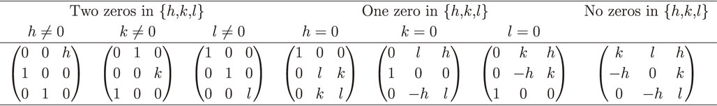
Table 1 Definition of M′ to obtain (a′′, b′′, c′′).
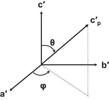
Next, an orthogonal coordinate system with basis vectors (a′, b′, c′) is derived such that vectors a′ and b′ are positioned in the (hkl) plane. This is attained by
| \begin{equation}
\mathbf{a}' = \mathbf{a}'',\quad \mathbf{c}' = \mathbf{a}'' \times \mathbf{b}'',\quad \mathbf{b}' = \mathbf{c}' \times \mathbf{a}'.
\end{equation}
| (3) |
The vector normal to the (
hkl) plane is parallel to
c′. In a similar manner, vectors normal to any plane, for example
$\mathbf{c'}_{\text{p}}$ for the (
hpkplp) surface, can be obtained. Here,
a′,
b′, and
c′ does not need to be lattice vectors. In fact, the lengths of (
a′,
b′,
c′) does not carry any significance because we are only interested in the relative direction of normal vectors of various facets. The polar and azimuth angles, which are denoted as θ and φ, respectively, are defined as in
Fig. 1. The vectors that are normal to pairs of facets that could form, where the orientations are denoted with indices (
h1k1l1) and (
h2k2l2), respectively, must satisfy
| \begin{equation}
\theta_{1} < 90^{\circ},\quad \theta_{2} < 90^{\circ},\quad | \varphi_{1} - \varphi_{2} | = 180^{\circ}.
\end{equation}
| (4) |
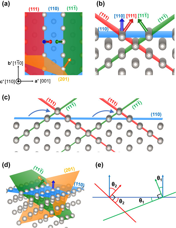
(a)–(c) shows an example for the (110) surface of Au, which takes the face-centered cubic structure.
Figure 2(a) illustrates how (111),
$(11\bar{1})$, and (201) surfaces intersect with the (110) surface. The [110] direction points out of the sheet, and the arrows in the figure are the vectors normal to the surfaces. There are two arrows that are antiparallel when projected to the original (110) orientation, which indicates that the difference of the azimuth angles is 180°. In this example, the projections of vectors normal of the (111) and
$(11\bar{1})$ surfaces are antiparallel, and these surfaces can form facets [
Fig. 2(b)]. A reconstructed model is shown in
Fig. 2(c). In contrast, the projections of vectors normal of the (201) and
$(11\bar{1})$ surfaces are not antiparallel, and these surfaces cannot form facets [
Fig. 2(d)]. Taking the surface energies of the (
hkl), (
h1k1l1) and (
h2k2l2) surfaces as
E0,
E1, and
E2, respectively, the surface energy decreases by formation of facets if [see geometry in
Fig. 2(e)]
| \begin{equation}
E_{0} > \frac{E_{1}\sin \theta_{2} + E_{2}\sin \theta_{1}}{\sin (\theta_{1} + \theta_{2})}.
\end{equation}
| (5) |
This is a macroscopic approximation where the influence of edges on the surface energy is not reflected. The surface energy of nanofacets, where the effect of edges is significant, must be individually obtained.
3. Applications
The above algorithm uses information of the lattice parameters and is independent on how atoms decorate the lattice. Setting limitations on the maximum and minimum values of indices is typically imposed in actual deployment of the algorithm. In other words, hmax, kmax, and lmax are predetermined and all combinations of |h1| ≤ hmax, |k1| ≤ kmax, and |l1| ≤ lmax, where h1, k1, l1 are coprime and not all zero, are investigated.
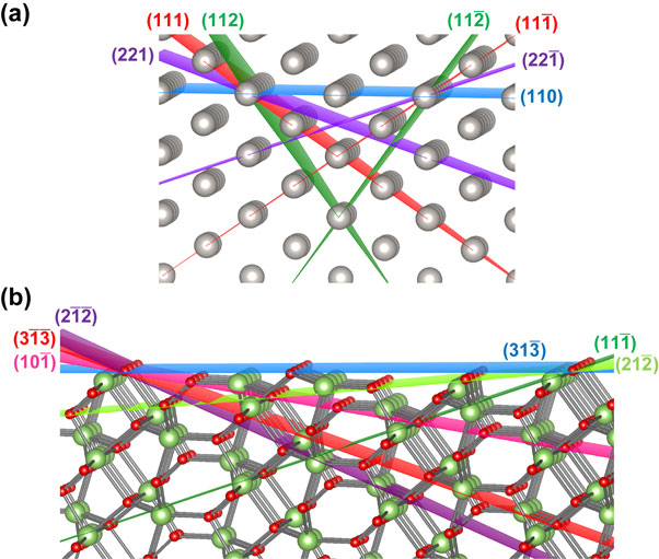
The (110) surface of Au is investigated first. Table 2 shows all facet candidates with hmax = kmax = lmax = 2. The two-fold rotation axis normal to the (110) surface ensures that, for each facet with θ1 and φ1, there is a corresponding facet with θ2 and φ2 where θ2 = θ1 and |φ2 − φ1| = 180°. The experimentally found (111) and $(11\bar{1})$ facet pair appears in the list with θ1 = θ2 ≈ 35.3° and φ1 = (φ2 − 180)° = 0° [Fig. 3(a)]. However, there are many other possibilities of facet formation, for instance the (221) and $(22\bar{1})$ pair. In fact, the surface area of facets from the (221) and $(22\bar{1})$ pair is smaller than the (111) and $(11\bar{1})$ pair. This is because the former pair has larger θ1 and θ2, and therefore the facets are inclined at a larger angle with respect to the latter pair.
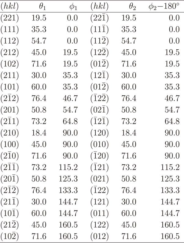
Table 2 Facet orientation candidates for the (110) orientation of a cubic lattice. Angles are in degrees.
The (211) surface of a cubic lattice is discussed next. This surface has been used as a surrogate surface to model under-coordinated step edge sites in face centered cubic metals because this surface can be viewed to consist of {111} and {100} facets. Examples of studies employing the fcc {211} surface include investigations on H adsorption on Pd,18) O adsorption on Pt,19) and methane reforming on Ni.20) Table 3 shows a list of facet surfaces with hmax = kmax = lmax = 2. The number of surfaces with 0° ≤ φ < 180° is no longer the same as those with 180 ≤ φ < 360°. The (100) and (111) pair appears in Table 3 with θ1 ≈ 35.3°, θ2 ≈ 19.5°, and φ1 = (φ2 − 180)° ≈ 39.2°. The condition (180 − θ1 − θ2) > 90° guarantees that there is no overhanging at the step when the model is considered as a step model. The two θ can be regarded as the angles of the wedges (σ and τ) in Ref. 10) [Fig. 2(e)].
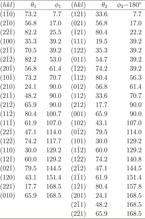
Table 3 Facet orientation candidates for the (211) orientation of a cubic lattice. Angles are in degrees.
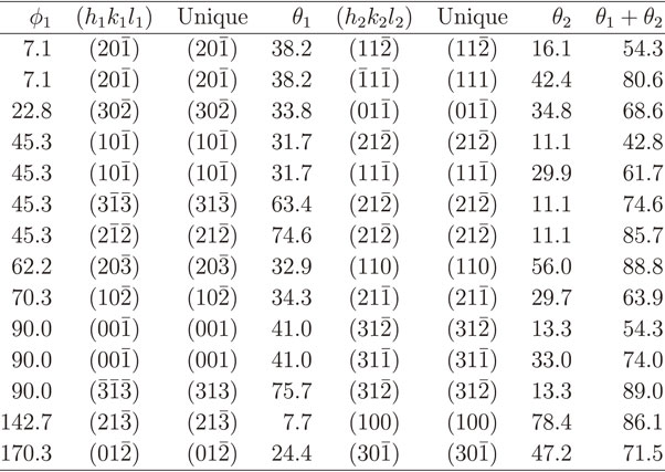
Finally, facet pairs for the $(31\bar{3})$ surface of β-Ga2O3 (computed lattice parameters of the crystallographic conventional cell are a = 12.3518 Å, b = 3.0710 Å, c = 5.8629 Å, β = 103.734°, α = γ = 90°) are shown in Table 4 as a complicated example. Here, hmax = lmax = 3, kmax = 1, and only facets that can be considered as a step model (θ1 + θ2 < 90°) are shown. Orientations with φ ≈ 45.3° and φ ≈ 225.3° are shown in Fig. 3(b). Combined with a library of surface energies, this type of information is useful to identify whether a surface is unstable with regard to spontaneous formation of facets. However, deriving such a table by hand is difficult and thus automated generation of geometrical facet data is critical for such analysis.
4. Conclusions
Facet pair formation is a type of reconstruction encountered in a number of material surfaces. This paper outlined an algorithm, applicable to any crystal orientation, to uncover orientations of facet pair candidates. Evaluation of the surface energy of the faceted surface is geometrically possible, thus surfaces that spontaneously reconstruct into facets can be identified. Formation of steps on a surface is a type of facet reconstruction, and candidates for the terrace plane can be obtained from knowledge of the vicinal surface orientation. The procedures in this paper is expected to further develop the field of high-throughput surface calculations.
Acknowledgments
This study was funded by the “Materials research by Information Integration” Initiative (MI2I) project of the Support Program for Starting Up Innovation Hub as well as a grant (No. JPMJCR17J3) from CREST of the Japan Science and Technology Agency (JST), and by a Kakenhi Grant-in-Aid (No. 18K04692) from the Japan Society for the Promotion of Science (JSPS). The VESTA code21) was used to draw Figs. 2 and 3.
REFERENCES
- 1) W. Mönch: Electronic Properties of Semiconductor Interfaces, (Springer, Berlin, 2010).
- 2) J. Robertson: J. Vac. Sci. Technol. A 31 (2013) 050821.
- 3) A. Grüneis, G. Kresse, Y. Hinuma and F. Oba: Phys. Rev. Lett. 112 (2014) 096401.
- 4) Y. Hinuma, A. Grüneis, G. Kresse and F. Oba: Phys. Rev. B 90 (2014) 155405.
- 5) Z.L. Wang, R.P. Gao, B. Nikoobakht and M.A. El-Sayed: J. Phys. Chem. B 104 (2000) 5417–5420.
- 6) S. Siebentritt, N. Papathanasiou, J. Albert and M.C. Lux-Steiner: Appl. Phys. Lett. 88 (2006) 151919.
- 7) Y. Hinuma, F. Oba, Y. Kumagai and I. Tanaka: Phys. Rev. B 86 (2012) 245433.
- 8) Y. Hinuma, Y. Kumagai, I. Tanaka and F. Oba: Phys. Rev. Mater. 2 (2018) 124603.
- 9) Y. Hinuma, Y. Kumagai, F. Oba and I. Tanaka: Comput. Mater. Sci. 113 (2016) 221–230.
- 10) Y. Hinuma, T. Kamachi and N. Hamamoto: Mater. Trans. 61 (2020) 78–87.
- 11) S. Curtarolo, G.L.W. Hart, M.B. Nardelli, N. Mingo, S. Sanvito and O. Levy: Nat. Mater. 12 (2013) 191–201.
- 12) G. Hautier, A. Miglio, G. Ceder, G.-M. Rignanese and X. Gonze: Nat. Commun. 4 (2013) 2292.
- 13) A.R. Oganov and C.W. Glass: J. Chem. Phys. 124 (2006) 244704.
- 14) A.R. Oganov, A.O. Lyakhov and M. Valle: Acc. Chem. Res. 44 (2011) 227–237.
- 15) A.O. Lyakhov, A.R. Oganov, H.T. Stokes and Q. Zhu: Comput. Phys. Commun. 184 (2013) 1172–1182.
- 16) Y. Hinuma, G. Pizzi, Y. Kumagai, F. Oba and I. Tanaka: Comput. Mater. Sci. 128 (2017) 140–184.
- 17) A. Togo: spglib, http://spglib.sourceforge.net/.
- 18) S. Hong and T.S. Rahman: Phys. Rev. B 75 (2007) 155405.
- 19) T. Ogawa, A. Kuwabara, C.A.J. Fisher, H. Moriwake and T. Miwa: J. Phys. Chem. C 117 (2013) 9772–9778.
- 20) D.W. Blaylock, Y.-A. Zhu and W.H. Green: Top. Catal. 54 (2011) 828.
- 21) K. Momma and F. Izumi: J. Appl. Crystallogr. 44 (2011) 1272–1276.