Abstract
The stretch flangeability of tailor-welded blank depends on the angle between weld line and the tangential line of blank edge, which is generally the tensile direction in stretch flanging. This effect was studied by uniaxial tensile testing of tailor-welded high-strength-steel specimens with a weld line at 45, 60, or 90 degrees from the tensile direction. The 60-degree-weld-line specimen provides the highest elongation at the maximum load. This is the angle at which the strain component in the weld-line direction is close to zero. At the other angles, the weld lines, of which hardness sufficiently increases by welding, play a role as a constraint for vicinal base metal. This leads to early strain localization and low elongation. Furthermore, the elongation at the maximum load can, in some cases, exceed the uniform elongation of base metal. This is pronounced by a base metal with a low n-value.
This Paper was Originally Published in Japanese in J. JSTP 59 (2018) 209–214.
1. Introduction
Recently, tailor welded blanks (TWB) has increasingly been applied to decrease car body weight, improvement of collision safety for passenger protection, reduction of the number of manufacture processes, and so on.1) TWB is a technological means on joining raw sheets with different material species and/or thickness together, or forming by joined sheets. TWB techniques can give the interior of a part with distributed strength and sheet thickness, differing from products from a sheet of homogeneous quality. After joining together the raw sheets, the blank is subjected to forming processes, which is similar to the process that is applied to typical raw sheets without welding (hereafter, referred to as one sheet). The formed products of TWB allow the manufacture of light-weight car parts and cars that exhibit excellent collision safety, i.e., highly efficient, because they can appropriately distribute the strength and thickness between various parts, which enable us to flexibly arrange.
However, before manufacturing the TWB parts, observations related to their forming behavior should be researched in a systematic manner because manufacturing a blank, which is joined together by welding, from sheets that exhibit uneven quality and thickness is different from the formation of conventional one sheet. For instance, the strain distribution that is generated in the base metal near a weld line is considerably likely to become uneven, it may reach breaking even in condition under which parts can be formed from one sheet. This is not only influenced by the constraint of the adjoining raw materials (which differ in strength and sheet thickness in general) separated by weld line, but also by weld metal hardened because of cooling after welding. In particular, at the blank end portion, which is the stretch flange deformation area, the end face is subjected to uniaxial stress, and therefore, the influence of restraint due to weld line having high deformation resistance tends to appear. Consequently, to determine the optimal arrangement of weld line, it is important to take up deformation that tends to concentrate strain on the base metal near the weld line during deformation and gain knowledge about its formability.
Many studies on TWB so far have evaluated the deformation behavior and characteristics of base metal, which varies with weld line, using a blank containing weld line. Mainly, it was examined by forming tests under relatively simple conditions, such as tension or stretching with weld line placed at 0° or 90° with respect to the main stress direction, and hole expansion with weld line placed at the center of the specimen.2–6) In other words, there are few design guidelines regarding the placement of specific weld lines with complex shaped parts in mind, and in particular, knowledge about the effect of the direction of the weld line on stretch flangeability is not sufficient. Therefore, in this study, the stress state at the flange end of stretch flange deformation is simulated by a uniaxial tensile test, and the weld line design conditions that give excellent formability are clarified, by using a test piece in which the angle between the tensile direction and weld line (hereinafter referred to as weld line angle) is changed. In general, TWB used for automotive parts are often used in combination with base metals with different strengths and thicknesses, but here, by using the same sheet thickness and material for base metal, only the influence of the deformation resistance of weld line is achieved. Note, for the evaluation of formability in this report, the elongation when the load carrying capacity limit is reached (hereinafter, apparent UEL), which corresponds to the uniform elongation (hereinafter, UEL) in the uniaxial tensile test, is used. Although this is not an index that directly indicates the fracture limit, it seems that it is not easy to control stably when the maximum load point is exceeded. Therefore, in this study, apparent UEL was adopted as an index indicating formability. In addition, the elongation with non-uniform deformation depends on the shape of the test piece and the distance gage length. Here, the distance between the JIS No. 5 test piece and the gage length of 50 mm is adopted.
2. Experimental Method
2.1 Specimens
Three steel materials A, B, and C were prepared as test materials. Table 1 shows the mechanical properties of the specimens. Figure 1 shows the sample shape and weld line arrangement. The specimen shape is JIS No. 5 specimen; the weld line angle for the tensile direction was set at three levels: 45°, 60°, and 90°. weld line was placed through the center of the specimen. For the specimen, cut the same kind of base sheet so that the rolling direction is the tensile direction, After laser butt welding, it was fabricated by machining. Table 2 shows the welding conditions. The welding start and end points are ideal edge point without irregularities because removed by machining. The weld thickness was almost the same as the base metal used.
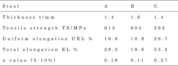
Table 1 Thicknesses and mechanical properties of Steels A, B and C.

Table 2 Welding conditions.
The tensile speed (crosshead movement speed) was set to 5 mm/min, and the elongation of the specimen was measured using an extensometer with a gage length 50 mm, and apparent UEL was used as an indicator of formability. Furthermore, in order to investigate the strain distribution in the base metal near the weld line during deformation, a 1 mm square lattice was laser-marked on the parallel part of the specimen, and the strain distribution during deformation was measured using a non-contact strain measuring instrument (Auto Grid, manufactured by ViALUX). In addition, in order to investigate the properties of welds, the hardness distribution of weld line and base metal near the weld line in steel grade A was measured by a micro Vickers hardness test. The indenter load was 2.9 N.
3. Results
3.1 Tensile strength and maximum tensile load elongation
Figure 2 shows the specimen after fracture. There is no effect of steel type on the failure mode. At weld line angle of 90°, it broke in the middle on one side of the base metal. At weld line angles of 45° and 60°, cracks occurred from the edge in the base metal width direction on the side where weld line and base metal near the weld line were obtuse. In other words, even in a tensile test where a normal single sheet has no strain gradient and cracks do not occur from the edges, in the case of TWB, the presence of weld line may promote cracks from the edges. It can be seen that this test is a condition for simulating stretch flange formability. At the weld line angle of 45°, cracks occurred from the base metal part closer to the weld line than the weld line angle of 60°. Figure 3 shows the relationship between the maximum tensile stress calculated from the maximum tensile load of each specimen and the weld line angle, and Fig. 4 shows the relationship between the apparent UEL and weld line angle. The maximum tensile stress showed the same value as the tensile strength (TS) of base metal regardless of weld line angle. On the other hand, the apparent UEL was higher than that of the other angles at the weld line angle of 60°, and more than the UEL of base metal in some specimen conditions.
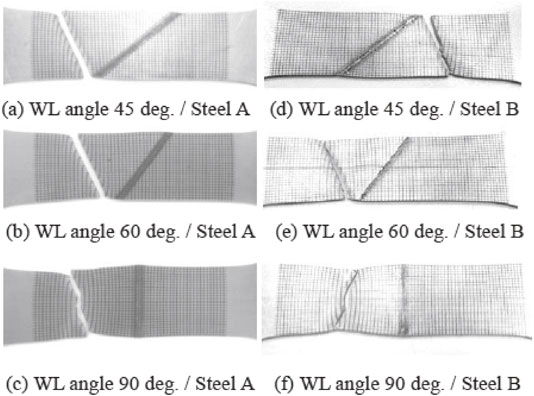
Figure 5 shows the hardness distribution of weld line and base metal near the weld line at a weld line angle of 90° for steel type A. In order to avoid the influence of the center segregation of the weld, the hardness measurement was performed at the 1/4 and 3/4 positions of the sheet thickness from the laser irradiation surface in the rolling direction. Weld metal is approximately 200 Vickers harder than base metal, and the deformation resistance of weld line is estimated to be sufficiently higher than that of base metal. Also, the elongation of weld line at 15% elongation in each specimen of steel type A was calculated from non-contact strain measurement images. Table 3 shows the measurement results. It can be seen that weld line is almost not deformed in any specimen.
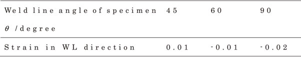
Table 3 Strain of weld line in weld line direction (Steel A, Nominal strain 15%).
4. Discussions
4.1 A mechanism by which the apparent UEL exhibits a peak at a weld line angle of 60°
Figures 6 and 7 show the equivalent strain distribution measured with a non-contact strain measuring instrument when the elongation is 15% for steel grade A and 14% for steel grade B. The equivalent strain is obtained from the measured strain assuming that the elastic strain component can be ignored and assuming the von Mises yield condition. All specimens are before reaching the maximum tensile load. The laser marking grid marked for strain distribution measurement is black and cannot be distinguished from weld line for image recognition.
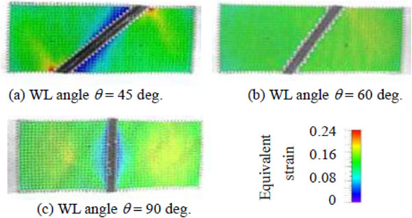
Therefore, the grid above or including the weld line is not recognized by photography, and the equivalent strain is not displayed. All steel types show a relatively uniform strain distribution across the entire parallel part of the specimen at a weld line angle of 60°. On the other hand, when the weld line angle was 45° and 90°, there was a difference in the amount of strain between the base metal near weld line and the region away from it. The strain distribution was uneven in the parallel part of the specimen. The reason why a high apparent UEL was obtained at a weld line angle of 60° is considered to be that a uniform strain distribution was obtained in the entire parallel part of the specimen. On the other hand, apparent UEL decreased at 45° and 90° because the load decreased early due to localization of deformation.
The reason for the non-uniform strain distribution in the parallel part of the specimen at weld line angles of 45° and 90° is presumed to be due to the difference in deformation resistance between weld line and base metal. In other words, since weld line has a large deformation resistance and does not expand or contract, it is assumed that the base metal near weld line is constrained in the weld line direction and the deformation is unevenly distributed. On the other hand, weld line angle of 60° is considered to be the direction in which weld line does not require expansion and contraction under uniaxial tension. Therefore, it is considered that the difference in deformation resistance was not affected. First, assuming that there is no difference in deformation resistance between weld line and base metal, the relationship between weld line angle and expansion and contraction is analyzed as follow.
The tensile coordinate system and weld line coordinate system are introduced with the center of the specimen as the origin. In the tensile coordinate system, the specimen longitudinal direction (tensile direction) is the x1 axis direction, the specimen width direction is the x2 axis direction, and the sheet thickness direction is the x3 axis direction. In the weld line coordinate system, the weld line direction is the X1 axis direction, the direction perpendicular to the weld line in the specimen surface is the X2 axis direction, and the sheet thickness direction is the X3 axis direction. The coordinate transformation from the tensile coordinate system to the weld line coordinate system is expressed by eq. (1).
The component Eij in the weld line coordinate system of the strain tensor due to tensile deformation is expressed by eq. (2) using the component εij in the tensile coordinate system.
| \begin{equation}
X_{\text{i}}=R_{ij}x_{j}
\end{equation}
| (1) |
| \begin{equation}
E_{ij} = R_{ij}R_{lk}\varepsilon_{jk}
\end{equation}
| (2) |
Since the angle formed by the weld line direction (X
1 axis direction) with respect to the tensile direction (x
1 axis direction) is the weld line angle θ,
eq. (3) is obtained.
| \begin{align}
&R_{11} = R_{22} = \cos\theta, \\
&R_{12} = -R_{21} = \sin\theta, \\
&R_{13} = R_{23} = R_{31} = R_{32} = 0, \\
&R_{33} = 1
\end{align}
| (3) |
When elastic deformation can be ignored, the strain path during deformation (norm of strain increment tensor) is constant, and the Rankford value in the rolling direction (tensile direction) is assumed to be r, the component in the tensile coordinate system of the strain tensor of a homogeneous body that is uniaxially tensioned in the x
1 direction (i.e., when weld line is also the same as base metal) is expressed by
eq. (4).
| \begin{align}
&\varepsilon_{12} = \varepsilon_{13} = \varepsilon_{21} = \varepsilon_{23} = \varepsilon_{31} = \varepsilon_{32} = 0, \\
&\varepsilon_{22}/\varepsilon_{11} = -r/(1 + r), \\
&\varepsilon_{33}/\varepsilon_{11} = -1/(1 + r)
\end{align}
| (4) |
Here, ε
11 takes a positive value because it corresponds to the elongation in the direction of the tensile axis. From these equations, the strain component
Eij in the weld line coordinate system normalized by ε
11 is expressed by
eq. (5).
| \begin{align}
&E_{11}/\varepsilon_{11} = \cos^{2}\theta - r/(1 + r) \sin^{2}\theta, \\
&E_{12}/\varepsilon_{11} = E_{21}/\varepsilon_{11} = -(1+2r)/(1+r) \sin\theta \cos\theta, \\
&E_{22}/\varepsilon_{11} = \sin^{2}\theta - r/(1 + r) \cos^{2}\theta, \\
&E_{33}/\varepsilon_{11} = -1/(1 + r), \\
&E_{13}/\varepsilon_{11} = E_{23}/\varepsilon_{11} = E_{31}/\varepsilon_{11} = E_{32}/\varepsilon_{11} = 0
\end{align}
| (5) |
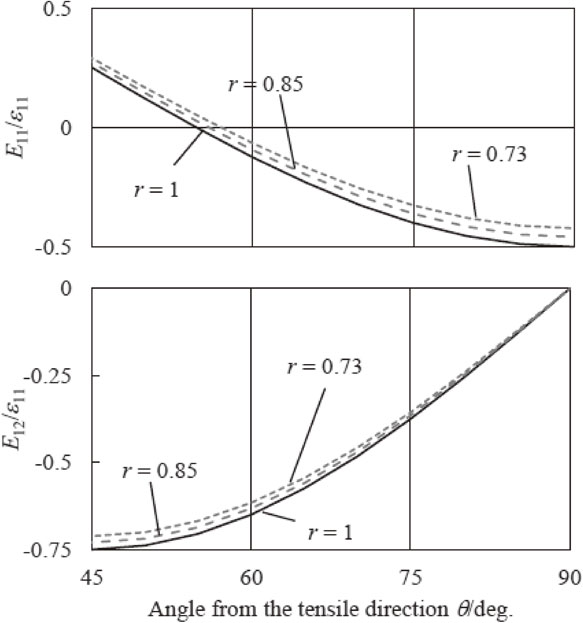
Based on
Fig. 8 obtained using
eq. (5), the expansion and contraction of weld line and the rotation of weld line due to uniaxial tensile deformation when weld line is assumed to be homogeneous with base metal can be understood as follows. weld line expansion/contraction corresponds to
E11/ε
11, but
E11/ε
11 = 0 (does not expand/contract in the direction of weld line) weld line angle θ is expressed by
eq. (6) according to the rankford value r in
eq. (5). The values shown in
Table 4 are for steel grades A and B.
| \begin{equation}
\theta = \tan^{-1}\{r/(1+r)\}^{1/2}
\end{equation}
| (6) |
When the weld line angle θ is smaller than this,
E11/ε
11 is a positive value, and weld line tries to stretch with tensile deformation. When weld line angle θ is larger than this,
E11/ε
11 is negative, and weld line tries to shrink with tensile deformation. On the other hand, weld line rotation corresponds to
E12/ε
11, but when weld line angle θ is 45°, weld line rotation is maximum. From these considerations when weld line is assumed to be the same quality as base metal, the effect of base metal near weld line when weld line’s deformation resistance is sufficiently higher than that of base metal is understood as follows according to weld line angle θ.
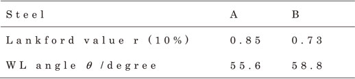
Table 4 Lankford value at 10% of tensile strain and weld line angle θ for E11 = 0.
When the weld line angle is 45°, the strain component in the weld line direction becomes positive (tensile strain) under the uniaxial tension condition of the homogeneous material, and the weld line tries to rotate toward the tensile axis direction. However, weld line, which has high deformation resistance and is difficult to stretch, exerts a force to pull the weld line end in the weld line direction, preventing rotation in the tensile axis direction. As a result, at the edge on the acute angle side, the longitudinal component of the specimen’s longitudinal force and the longitudinal component of the pulling force in the weld line direction cancel each other, reducing the tensile elongation that requires weld line rotation suppression, and the strain is reduced. On the other hand, at the obtuse end, the longitudinal component of the pulling force in the weld line direction is added to the tensile force in the longitudinal direction of the test piece, increasing the elongation in the tensile direction that requires weld line rotation suppression and increasing the strain. The strain distribution shown in Fig. 6 and Fig. 7(a) can be understood as described above.
When the weld line angle is 60°, the strain component in the weld line direction is extremely small under the uniaxial tension condition of the homogeneous material. Therefore, even if the deformation resistance of weld line is high, it matches the strain of base metal near weld line. Since no restraining force is generated by weld line, weld line rotation proceeds in the same way as homogeneous material. As a result, it can be understood that the uniform strain distribution shown in Fig. 6 and Fig. 7(b) is obtained as in the case of the homogeneous material.
When the weld line angle is 90°, the strain component in the weld line direction is negative (shrinkage) under the uniaxial tension condition of the homogeneous material. And, weld line with high deformation resistance and not shrinking restrains the shrinkage in the weld line direction. On the other hand, both ends in the longitudinal direction of the parallel part of the test piece (grip section) also restrain the deformation in the width direction. Obviously, the deformation is extremely symmetric because there is no rotation. As a result, the width reduction deformation is concentrated in the position of the farthest longitudinal 1/4 and 3/4 from the constraint. The strain distribution shown in Fig. 6 and Fig. 7(c) can be understood as described above.
From the above, it is considered that a uniform strain distribution is obtained in the entire parallel part of the specimen at a weld line angle of 60°, and a high apparent UEL is obtained. On the other hand, at weld line angle of 45° and 90°, the load drop was accelerated by the localization of deformation, and the apparent UEL is considered to be lower than weld line angle of 60°. In the TWB forming simulations that are carried out industrially, in general, weld line is only defined as the boundary line where different base metals touch and it is rare to model weld line as a part with different materials. This finding suggests that the hardened weld line may promote stretch flange breakage, which is particularly useful when using a high-strength steel sheet TWB where stretch flange breakage is a problem.
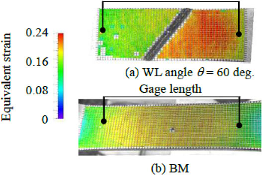
4.2 A mechanism by which the apparent UEL of TWB surpasses the UEL of base metal
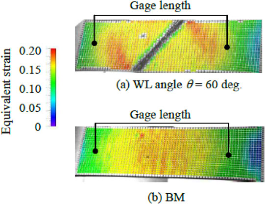
The weld line angle of 60° in steel grade A, and all weld line angles specimens in steel grade B showed an apparent UEL exceeding that of base metal. Figure 9 shows the equivalent strain distribution at 16% elongation of a single sheet and TWB with a weld line angle of 60° in steel grade A. Even before the maximum load is reached, even with a single sheet, unbalanced distribution of strain is observed between the gage length.7) In addition, Fig. 10 shows the longitudinal strain distribution of the 50 laser marking gratings included in the gage length. The single sheet shows higher strain in the center between the gage length than the surroundings, but in the TWB specimen with a weld line angle of 60°, high strain is distributed in the two base metal regions separated by weld line. Generally, in plastic deformation in a tensile test, stress concentrates on the connection R between the parallel part of the specimen and the grip part, and a slip band is generated from there.8)

Corresponding to this slip band, only the specimen with a weld line angle of 60° exceeded the UEL of base metal in the case of steel grade A, all TWB specimens exceeded the UEL of base metal in the case of steel grade B. Figure 11 shows the equivalent strain distribution of base metal and each TWB specimen of steel grade B when the elongation is 10%. In TWB, strain occurs in two regions separated by weld line, as in the case of steel grade A with a weld line angle of 60°, but in shingle sheet of base metal, strain is concentrated locally in the center of the tensile test specimen. This is thought to be influenced by the n value of the specimen. In this test, the n value of steel type B is lower than that of steel type A, so the apparent UEL of TWB of steel type B is thought to be higher than that of base metal. In other words, by providing a deformation starting point in the parallel part of the tensile test piece, the strain between the gage length is dispersed and the apparent UEL is improved, and this effect is presumed to be greater as the n value is lower. In order to verify the influence of the n value of the specimen, TWB tensile specimens with a weld line angle of 60° were prepared using steel grade C, which has a larger n value than steel grades A and B, and compared with the base metal tensile test results. Figure 12 shows the effect of the base metal n value on the apparent UEL. As the n value increased, the TWB apparent UEL and the base metal UEL tended to increase, but in the steel grade C, the TWB apparent UEL was lower than the UEL of base metal. Figure 13 shows the equivalent strain distribution of TWB of steel grade C with a weld line angle of 60° and a single sheet (base metal) with an elongation of 20%. At a weld line angle of 60°, strain concentrates on one side base metal, showing a unbalanced distribution with strain compared to the single sheet (base metal) in Fig. 13(b). The mechanism is an issue for the future, which corresponds to the low UEL of the TWB of steel grade C with a weld line angle of 60°.

5. Conclusion
The effect of weld line placement condition of TWB on stretch flange deformation was investigated. A tensile test was carried out by changing the angle between the tensile direction and weld line, and the following knowledge was obtained as a design guide for improving stretch flange formability.
-
(1)
The deformation of the base metal near the weld line can be made uniform by placing the weld line at an angle that reduces the strain component in the weld line direction of the base metal near the weld line. As a result, high maximum tensile load elongation can be obtained in the uniaxial tensile test. In other words, the risk of end fracture due to the presence of high hardness weld line during stretch flange forming can be reduced.
-
(2)
When the n value of base metal is small, the strain distribution within the gage length in base metal becomes non-uniform even before reaching UEL. In the case of TWB, deformations between gage length can be distributed by constraint of weld line. As a result, in uniaxial tensile tests, TWB may exhibit maximum tensile load elongation that exceeds the UEL of base metal.
REFERENCES
- 1) O. Yokoyama: J. JSTP 54 (2013) 309–313.
- 2) M. Uchihara and K. Fukui: J. Jpn. Weld. Soc. 23 (2005) 541–548.
- 3) M. Uchihara and K. Fukui: J. Jpn. Weld. Soc. 23 (2005) 549–557.
- 4) Y. Miyazaki, T. Sakiyama and S. Kodama: Nippon Steel Technical Rep. 385 (2006) 42–47.
- 5) T. Tomokiyo, Y. Taniguchi, R. Okamoto, R. Miyagi and S. Furusako: J. JSTP 48 (2007) 1012–1016.
- 6) M. Ono, A. Yoshitake and M. Ohmura: J. Jpn. Weld. Soc. 21 (2003) 560–567.
- 7) A. Nadai: Theory of Flow and Fracture of Solids, (McGraw-Hill, New York, 1950) pp. 316–327.
- 8) K. Yoshida: J. JSTP 38(5) (1964) 56–64.