Abstract
Thermal barrier coatings (TBCs) applied to turbine blades in jet engines or gas turbines are at risk of high-velocity impingement from different foreign objects, which can cause severe damage from delamination of the TBC. In this study, a high-velocity impingement test system is developed under high-temperature conditions to understand the delamination mechanism of TBCs under actual operation conditions. In this system, a spherical impactor with a diameter of 1–8 mm can be impinged onto a TBC specimen at different temperatures up to 900°C. High-velocity impingement tests were conducted on atmospheric plasma-sprayed TBC specimens with 8 mass% yttria-stabilized zirconia topcoat (TC) under room temperature (RT) and 900°C conditions. The results indicate that a hemispherical indentation was formed at 900°C, which indicates plastic deformation of the TC, unlike the brittle deformation observed at RT. In addition, vertical and interfacial cracks formed under both RT and 900°C conditions. Cross-sectional observation revealed that the formation process of the interfacial crack at 900°C was different from that at RT. In particular, the interfacial crack tended to become significantly longer at more than 170 m/s at 900°C.
This Paper was Originally Published in Japanese in the J. Japan Thermal Spray Society 58(1) (2021) 4–10. The abstract and captions of Figs. 1–8, 10 and 11 were slightly modified from the original paper.
1. Introduction
Thermal barrier coatings (TBCs) are widely applied to the surfaces of turbine blades in jet engines and gas turbines in thermal power plants to protect the metallic substrate from high-temperature combustion gas flow.1) TBCs typically consist of two layers; one is a ceramic top coating (TC) with low thermal conductivity, and the other is a metallic bond coating (BC) for suppression of the mismatch of thermal expansion coefficients between the TC and substrate.2) The TC layer is typically deposited by atmospheric plasma spraying (APS) or electron beam-physical vapor deposition (EB-PVD). The former is employed for land-based gas turbines; the latter is employed for jet engines.
TBCs are exposed to high-temperature environments during operation. Delamination of the TC layer is induced by aging degradations such as oxidation of the BC layer. Numerous researchers have attempted to improve the delamination resistance of the TC layer. Katayanagi et al. proposed an improvement method for the delamination resistance of the TC layer. This method positively promotes the internal oxidation of the BC by adding a small amount of CeO2 or ZrO2 to the CoNiCrAlY matrix, which is typically used for a BC.3) Ito et al. reported that the interfacial fracture toughness can be improved by removing unmelted particles and controlling the TC/BC interfacial roughness by polishing and grit-blasting the BC surface.4)
In addition to such aging degradations, sudden damage caused by the impingement of foreign objects must be addressed. When foreign objects such as sand, volcanic ash, and tiny metallic fragments are ingested into a jet engine or gas turbine, the high-velocity impingements of the foreign objects onto the surface of the turbine blade can lead to cracks or delamination of the TC layer. This type of damage is called foreign object damage (FOD), and is particularly problematic in jet engines.5,6) FOD can cause delamination of the TC layer, which can lead to severe damage to the jet engine or gas turbine. Therefore, it is necessary to clarify the damage mechanism of TBCs caused by FOD.
Research regarding the damage mechanism of TBCs caused by FOD is being actively conducted globally.7–9) Chen et al. evaluated the damage mechanism of TBCs formed by EB-PVD based on the burner rig test.10) In this test, alumina powder with a diameter of 50–560 µm was injected into a high-temperature combustion gas frame and impinged onto the surface of a TBC specimen heated at 1232°C in the velocity range of 10–170 m/s. In addition, the interfacial crack length formed at the TC/BC interface was estimated based on the energy release rate evaluated from the stress distribution obtained by finite element analysis (FEA). The results indicated that the estimated interfacial crack length was virtually consistent with that observed in the experiment. However, it was difficult to reveal the causality, i.e., rigorously associating the individual impingement of particles with the resultant damages in this kind of experiment where numerous small particles impinge onto a specimen.
Choi et al. investigated the damage mechanism of TBCs formed by EB-PVD based on a high-velocity impingement test with a solid sphere.11) In this test, a high-carbon chromium steel ball (JIS code: SUJ2) with a diameter of 1.6 mm was impinged onto a TBC specimen at 150–300 m/s. Subsequently, the interfacial crack length formed at the TC/BC interface resulting from the impingement test was measured. In addition, they proposed an equation for the estimation of the interfacial crack length based on the energy conservation during the impingement process and reported that the interfacial crack length estimated by the proposed equation was in reasonable agreement with that evaluated by the impingement test. Unlike an experiment based on numerous small particle impingements, the impingement of a projectile can be definitively associated with the resultant damage in the high-velocity impingement test using a solid sphere. Therefore, it is a powerful method for clarifying the damage mechanism of TBCs caused by FOD. The majority of impingement tests have been conducted at room temperature (RT). However, it is important to evaluate the damage caused under high-temperature environments that are closer to the actual environment in gas turbines.
Our research group has developed a high-velocity impingement testing system where a solid sphere can be impinged onto a TBC specimen at RT.12) Using this system, the damage mechanism of TBCs and metallic substrates caused by FOD has been investigated.13,14) In this study, to clarify the damage mechanism of TBCs caused by FOD under a high-temperature environment, a new high-velocity impingement testing system (H-SPITS) wherein a solid sphere can be impinged at environmental temperatures up to 900°C is developed. The influences of temperature and impingement velocity on the deformation and damage behaviors of TBCs are investigated through a high-velocity impingement test conducted at RT and 900°C. In addition, the problem of interfacial crack formation is discussed by simulating the impingement of a solid sphere on a TBC specimen using FEA.
2. Outline of Developed H-SPITS
A schematic of the H-SPITS is displayed in Fig. 1. In this system, a solid sphere (projectile) with a diameter of 1–8 mm is accelerated through a stainless steel pipe by high-pressure nitrogen (N2) or helium (He) gas, followed by impingement onto the surface of a TBC specimen placed in a vacuum chamber. A cylindrical ceramic fiber heater (VC401E06A, Sakaguchi E.H VOC Corp., Japan) is installed in the vacuum chamber. A quartz glass pipe is placed in the heater. A cylindrical-shaped TBC specimen with a marginally smaller diameter than the inner diameter of the quartz glass pipe can be used. It is inserted into the quartz glass pipe from the rear side of the vacuum chamber. The temperature of the specimen can be controlled to a target value using a K-type sheathed thermocouple (1HKX325, CHINO Corporation, Japan) and desktop-type temperature control device (DSSP23, SHIMADEN Co., Ltd., Japan). As indicated in Fig. 1, the specimen is not located in the center of the heater but marginally in front of it to prevent damage to the heater by a rebounded projectile. In addition, the thermocouple contacts the rear surface of the specimen. Therefore, it should be noted that a small temperature gradient is generated in the specimen. In fact, for the high-temperature test, the rear surface of the specimen was heated to approximately 950°C to maintain the front surface temperature at 900°C.

The vacuum chamber in the H-SPITS is displayed in Fig. 2. The pressure in the vacuum chamber can be moderated by an oil-sealed rotary vacuum pump (G50DA, ULVAC KIKO, Inc., Japan) up to approximately 500 Pa. Thus, the oxidation of the specimen can be suppressed even under maximum temperature conditions. Moreover, the low air resistance contributes to the enhancement of the impingement velocity of the projectile. The impingement velocity of the projectile is measured using two continuous wave semiconductor lasers (LDU33, SIGMAKOKI CO., LTD., Japan) placed at a 60 mm interval. The time gap between these two lasers obscured by a projectile is detected using an oscilloscope (DCS-7506, TEXIO TECHNOLOGY CORPORATION, Japan).

The specifications of the H-SPITS are summarized in Table 1. The maximum impingement velocity depends on the size of the projectile. A maximum impingement velocity of 700 m/s can be achieved with a projectile of 1 mm diameter, while that is restricted to 450 m/s with a projectile of 3 mm diameter.

Table 1 Specification of H-SPITS.
3. Damage Evaluation of TBC via H-SPITS
3.1 Materials and experimental procedure
Ni-based superalloy Hastelloy-X with a cylindrical shape φ23.5 × 21 mm was used as the substrate material. The surface of the substrate was roughened by grit-blasting treatment. A CoNiClAlY alloy (AMDRY9954, Oerlikon Metco Japan Ltd., Japan) was deposited on the roughened surface of the substrate as a BC layer using the high-velocity oxygen fuel technique (UnicoatLF/JP5000 gun, Oerlikon Metco Japan Ltd., Japan) and 0.1 mm thickness. Subsequently, 8 mass% Y2O3–ZrO2 (8YSZ, METCO 204NS, Oerlikon Metco Japan Ltd., Japan) was deposited on the BC layer by APS (Unicoat/F4 gun, Oerlikon Metco Japan Ltd., Japan) up to a thickness of 1 mm. This specimen was denoted as the TBC specimen. SUJ2 balls with a diameter of 3 mm (Ohashikokyu Co., Ltd., Japan) were employed as projectiles.
A high-velocity impingement test was conducted at RT and 900°C using the H-SPITS. In the case of the impingement test at 900°C, the pressure in the vacuum chamber was reduced to approximately 500 Pa using a vacuum pump after inserting the TBC specimen into the chamber. Subsequently, the TBC specimen was heated to 900°C at 10°C/min and maintained at 900°C for 10 min. After the impingement test, the TBC specimen was naturally cooled in the chamber until the temperature decreased to less than 150°C. The impingement velocity of the projectile was controlled in the range of 100–300 m/s by the acceleration gas type and gas pressure. After the test, the indentation morphology and indentation depth formed on the surface of the TBC specimen were evaluated using a laser microscope (VK-X150, KEYENCE CORPORATION, Japan). In addition, the surface and cross-section of the specimens were observed using a scanning electron microscope (SEM, JCM-6000, JEOL Ltd., Japan) to evaluate the vertical cracks and interfacial crack lengths.
3.2 Experimental results and discussions
Figure 3 displays laser microscope images of the surface of the TBC specimens subjected to an impingement of an SUJ2 ball at 271 m/s under RT and 900°C. The brightness of the figure represents the height from the reference plane. The reference plane was set as the average height of four points, being sufficiently distant from the indentation. Focusing on the result for RT, the indentation had an irregular shape with severe asperity; it can be confirmed that cracks and delamination occurred around the indentation. Conversely, at 900°C, a neat hemispherical indentation was formed, and no large cracks or delamination were observed around the indentation. Thus, it was found that TC demonstrated brittle deformation and damage behavior at RT, whereas it indicated high plastic deformation ability under high-temperature, such as the 900°C environment. This tendency was irrespective of the impingement velocity. Watanabe et al. conducted a ball indentation test on 7YSZ-TBC formed by EB-PVD at high-temperature.15) It was reported that remarkable deformation and densification of the columnar structure of the TBC around the indentation occurred at 1137°C. In our results, plastic deformation occurred at a relatively low temperature of 900°C. In the future, the mechanical properties of YSZ formed by APS at high temperatures should be evaluated.

Figure 4 displays the relationship between the impingement velocity and indentation depth measured using a laser microscope. It can be observed that the indentation depth monotonously increased as the impingement velocity increased at both temperatures. However, this tendency was significantly different depending on the temperature. At a relatively high impingement velocity—more than 200 m/s—the indentation became deeper at RT than at 900°C. This is attributed to the formation of deep valleys locally related to the cracks and delamination inside and around the indentation, as indicated in Fig. 3(a). Conversely, at a relatively low impingement velocity, less than 150 m/s, the indentation became deeper at 900°C. In this velocity range, large cracks and delamination did not appear, even at RT. Therefore, a deeper indentation was formed at 900°C, where the TC could be plastically deformed owing to thermal softening.

Figure 5 displays SEM images of the surface of the TBC specimen subjected to the impingement of a SUJ2 ball at 271 m/s under RT and 900°C. These figures show that numerous cracks were radially formed by the indentation toward the surroundings at both temperatures. Hereafter, these cracks are called vertical cracks. The relationship between the impingement velocity and number of vertical cracks and the relationship between the impingement velocity and maximum length of the vertical cracks are displayed in Figs. 6 and 7, respectively. From these graphs, it can be observed that the number of vertical cracks and maximum length of the vertical cracks increased as the impingement velocity increased, although these fluctuated only marginally. Conversely, no clear influence of temperature was observed on these tendencies. The formation of such vertical cracks can be qualitatively explained by the press-fitting problem of the cylinder. That is, in the impingement process of the SUJ2 ball on the TC surface, compressive stress was generated in the TC in the radial direction. Conversely, tensile stress was generated in the TC in the circumferential direction. This tensile stress resulted in the formation of the vertical cracks.


Figure 8 displays cross-sectional SEM images of the TBC specimens subjected to the impingement of an SUJ2 ball under different conditions. The results of low, medium, and high impingement velocities within the experimental range are provided in Fig. 8(a) and (b), (c) and (d), and (e) and (f), respectively. From the result of the low impingement velocity, a cone crack propagating diagonally from the center of the TC immediately below the indentation toward the TC/BC interface was formed at RT. This cone crack was deflected in a direction parallel to the interface near the interface. In addition, an interfacial crack was formed at the TC/BC interface immediately below the indentation. Conversely, no cone cracks were observed at 900°C, and only an interfacial crack was formed immediately below the indentation. At medium impingement velocities, cone cracks propagated along the interface at RT, and lateral cracks propagated horizontally from the bottom of the indentation. At 900°C, it can be confirmed that an interfacial crack formed immediately below the indentation propagated in the TC, and other interfacial cracks formed at the TC/BC interface away from the indentation. In the case of high impingement velocities, at RT, interfacial cracks originating from cone cracks further developed along the interface. In addition, numerous cracks occurred in the TC immediately below the indentation, inducing serious damage to the TC. It can be confirmed that the interfacial cracks developed further at 900°C. These observations indicate that the formation process of interfacial cracks and cracks inside the TC due to the impingement of a solid sphere is significantly different at RT and 900°C.

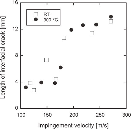
Figure 9 displays the relationship between the impingement velocity and length of the interfacial crack at RT and 900°C. In this study, the horizontal distance between the crack tips, indicated in Fig. 8, was defined as the length of the interfacial crack. From the graph, the length of the interfacial crack tended to increase with the impingement velocity at both temperatures. Although there is no clear difference related to the temperature, it can be confirmed that the length of the interfacial crack tended to increase sharply at 170 m/s and 900°C. As mentioned above, at less than 170 m/s, only an interfacial crack was formed, and it grew immediately below the indentation, whereas at more than 170 m/s, other interfacial cracks were formed at the interface away from the indentation. The formation of these interfacial cracks led to the sharp increase, as confirmed in Fig. 9.
4. Simulation of Impingement Process Based on FEA
4.1 Analysis model and conditions
To clarify the factors resulting in the interfacial cracks observed in the impingement test, the impingement process of a solid sphere onto a TBC specimen was simulated via FEA. The commercial FEA code Marc (Ver. 2020, MSC Software Corporation, USA) was used for the analysis. Figure 10 displays the schematic of the axisymmetric FEA model of a TBC specimen subjected to high-velocity impingement by a spherical projectile. The sizes of the projectile and TBC specimen were set to be the same as those in the experiment. The projectile was an elastic body, TC and BC were elastic-perfectly plastic bodies, and the substrate was an elastoplastic body obeying the Johnson–Cook (JC) flow stress model.16) Table 2 lists the mechanical properties of the projectile, TC, BC, and substrate used for the analysis. The material constants of the JC model for the substrate are listed in Table 3. The yield stress of the TC was determined such that the indentation depth obtained by this analysis corresponded to that obtained from the impingement test at 900°C. It was assumed that the projectile was SUJ2, BC was CoNiCrAlY, and the substrate was Hastelloy-X. The mechanical properties of the BC and substrate were cited from the literature.17,18) The friction and thermal conduction at the contact interface between the projectile and TC were not considered. The effect of heat generation due to plastic deformation was also neglected. The minimum element size was set at 25 µm. The area near the indentation was automatically remeshed at every increment during the simulation to prevent excessive deformation of the elements. The impingement velocity was fixed at 200 m/s. The stress distribution in the z-direction near the TC/BC interface, which induces delamination of the TC, was evaluated.


Table 2 Mechanical properties of TC, BC, and substrate used for analysis.

Table 3 Material constants of JC model of substrate used for analysis.
Figure 11 displays the contour plot of the z-direction stress σzz in the TBC specimen during the impingement process obtained by FEA. Only tensile stress is indicated as a contour plot; the entire compressive stress region is indicated in white. As indicated in Fig. 11(a), when the projectile achieved the maximum penetration depth, compressive stress was generated in the TC, BC, and substrate immediately below the indentation. In addition, tensile stresses of several tens of MPa were generated at the TC/BC interface away from the indentation. However, as displayed in Fig. 11(b), a tensile stress exceeding 100 MPa was instantaneously generated at the TC/BC interface immediately below the indentation at the moment the projectile bounced off. In addition, a tensile stress exceeding 300 MPa was generated near the indentation edge. As indicated in Fig. 11(c), the stress at the interface immediately below the indentation became compressive again after the projectile bounced off. Conversely, it can be observed that a high-tensile stress was generated at the TC/BC interface away from the indentation. This tensile stress was greater than that observed when the projectile achieved the maximum penetration depth.

From these results, it can be considered that the interfacial crack immediately below the indentation observed in Fig. 8 was formed by the instantaneous tensile stress immediately after the projectile bounced off. The instantaneous tensile stress was not confirmed by the impingement analysis of the projectile on the TC monolayer specimen. This indicates that the difference in the mechanical properties of each layer results in tensile stress. However, the generation mechanism of tensile stress is not well understood. Therefore, we will experimentally investigate the mechanism and establish a theoretical model as a future work. On the other hand, the tensile stress generated during the projectile penetration or after the projectile bounced off led to the formation and growth of other interfacial cracks formed at the interface away from the indentation.
As a complementary analysis, a thermal stress analysis was conducted using a TBC model with a precrack introduced at the TC/BC interface. It was confirmed that the energy release rate at the crack tip after the model was cooled from 900°C to RT was approximately 0.2 N/m. The interfacial fracture toughness at the TC/BC interface in general TBCs is approximately 1.0 MPa·m0.5.19) The critical energy release rate becomes approximately 15 N/m after converting the interfacial fracture toughness to the critical energy release. This indicates that the possibility of interfacial crack growth during cooling was significantly low.
5. Conclusion
To clarify the damage mechanism of TBCs subjected to high-velocity impingement by a foreign object under a high-temperature environment, we developed an original H-SPITS. Using this system, an SUJ2 ball with a diameter of 3 mm was impinged onto a TBC specimen in the velocity range of 100–300 m/s at RT and 900°C. The surface and cross-section of the TBC were observed to evaluate the damaged conditions. We also performed an FEA to investigate the factors of crack formation. The conclusions are summarized as follows:
-
(1)
The results of the impingement test confirmed that the deformation behavior of the TC significantly depends on the temperature. TC exhibited brittle deformation behavior at RT, whereas ductile deformation behavior was observed at 900°C.
-
(2)
At both temperatures, vertical cracks formed radially from the indentation toward the surroundings. The number of vertical cracks and their maximum length increased with the impingement velocity; however, the influence of temperature on these values was not confirmed.
-
(3)
Cross-sectional observations revealed that interfacial cracks were formed at the TC/BC interface in all velocity ranges, irrespective of the temperature. In addition, the process of interfacial crack formation differed significantly depending on the temperature. It was also confirmed that the length of the interfacial crack increased with the impingement velocity and increased sharply at greater than 170 m/s at 900°C.
-
(4)
From the FEA, it was confirmed that a relatively large tensile stress was instantaneously generated at the TC/BC interface immediately after the projectile bounced off. In addition, tensile stress was also generated at the TC/BC interface away from the indentation during the penetration and bouncing process of the projectile. It was concluded that these tensile stresses led to the formation of interfacial cracks.
Acknowledgments
This study was supported by a research grant from the Japan Thermal Spray Society in 2019. We would like to express our gratitude to TOCALO Co., Ltd. for constructing the TBC specimens.
REFERENCES
- 1) A.G. Evans, D.R. Mumm, J.W. Hutchinson, G.H. Meier and F.S. Pettit: Prog. Mater. Sci. 46 (2001) 505–553. doi:10.1016/S0079-6425(00)00020-7
- 2) K. Ogawa, K. Ito, T. Shoji, D.W. Seo, H. Tezuka and H. Kato: J. Therm. Spray Technol. 15 (2006) 640–651. doi:10.1361/105996306X147081
- 3) G. Katayanagi, Y. Ichikawa, K. Ogawa, T. Tatsuki, M. Tada and Y. Shibasaki: J. JTSS 57 (2020) 97–104. doi:10.11330/jtss.57.97
- 4) K. Ito, T. Shima, M. Fujioka and M. Arai: J. Therm. Spray Technol. 29 (2020) 1728–1740. doi:10.1007/s11666-020-01057-y
- 5) C.B. Meher-Homji and G. Gabriles: Proc. of The 27th Turbomachinery Symposium (1998) pp. 129–180.
- 6) X. Chen, M.Y. He, I. Spitsberg, N.A. Fleck, J.W. Hutchinson and A.G. Evans: Wear 256 (2004) 735–746. doi:10.1016/S0043-1648(03)00446-0
- 7) J. Kadkhodapour, A. Pourkamali Anarakia and B. Taherkhani: J. Fail. Anal. Prev. 15 (2015) 272–281. doi:10.1007/s11668-015-9926-7
- 8) W. Zhu, Y.J. Jin, L. Yang, Z.P. Pi and Y.C. Zhou: Wear 414–415 (2018) 303–309. doi:10.1016/j.wear.2018.08.020
- 9) X. Chen, R. Wang, N. Yao, A.G. Evans, J.W. Hutchinson and R.W. Bruce: Mater. Sci. Eng. A 352 (2003) 221–231. doi:10.1016/S0921-5093(02)00905-X
- 10) M.W. Crowell, T.A. Schaedler, B.H. Hazel, D.G. Konitzer, R.M. McMeeking and A.G. Evans: Int. J. Impact Eng. 48 (2012) 116–124. doi:10.1016/j.ijimpeng.2011.10.006
- 11) S.R. Choi, J.M. Wright, D.C. Faucett and M. Ayre: J. Eng. Gas Turbines Power 136 (2014) 102603. doi:10.1115/1.4027362
- 12) K. Ito, Y. Ichikawa and K. Ogawa: J. JTSS 52 (2015) 141–146. doi:10.11330/jtss.52.141
- 13) K. Ito, F. Gao and M. Arai: Key Eng. Mater. 827 (2019) 349–354. doi:10.4028/www.scientific.net/KEM.827.349
- 14) K. Ito and M. Arai: J. Eng. Mater. Technol. 142 (2020) 021005. doi:10.1115/1.4045329
- 15) M. Watanabe, C. Mercer, C.G. Levi and A.G. Evans: Acta Mater. 52 (2004) 1479–1487. doi:10.1016/j.actamat.2003.11.029
- 16) G.R. Johnson and W.H. Cook: Proc. 7th International Symposium on Ballistics (1983) pp. 541–547.
- 17) M. Arai, H. Katori and K. Ito: Surf. Coat. Technol. 399 (2020) 126159. doi:10.1016/j.surfcoat.2020.126159
- 18) A. Sandeep: Open Access Dissertations Paper 31 (2013).
- 19) M. Arai: J. Soc. Mater. Sci. Japan 58 (2009) 917–923. doi:10.2472/jsms.58.917