Mechanics of Materials
Fatigue Characteristics of DP780 Steel Spot Welding Joints with Different Static Fracture Modes
2021 Volume 62 Issue 2 Pages 191-197

Details
2021 Volume 62 Issue 2 Pages 191-197
Two specimens made of DP780 dual phase steels were produced by resistance spot welding and the quality was evaluated by the static tension-shear test and low cycle fatigue test. The fracture characteristics, macrostructure, microstructure, microhardness distribution and fatigue morphology were studied. The results show that the nugget size and microhardness gradient in the heat affected zone affect the static load-bearing performance and the fracture mode. Meanwhile, applied load, microhardness gradient in the heat affected zone and inclined angle on faying surface caused by macro deformation have influence on the low cycle fatigue life. Compared with the specimen which has high static load-bearing capacity, samples with lower static load capacity has a higher fatigue life and plastic deformation characteristics under the same applied load of 40% of its static load-bearing capacity, which indicates that the applied load is the controlling factor in the low cycle fatigue test.

Fig. 2 Typical fracture modes of RSW joints, interfacial fracture (a) and pull-out fracture (b).
Lightweight has become a trend in the field of automotive.1) Optimization of body structure design and usage of lightweight materials are main ways to realize the lightweight of automotive. Although aluminum alloy is a potential lightweight material, the development of advanced high strength steel (AHSS) have found a good balance between lightweight and safety of automotive.2) As one kind of AHSS, dual phase steel has better properties in strength, work hardening rate, strain energy absorption rate and formability compared with conventional high strength low alloy steel with similar strength.3) Dual phase steel has a ferrite matrix and martensite as second phase. This dual microstructure can balance strength and ductility, which is very attractive for automotive industry.4)
Resistance spot welding (RSW) has been used widely in automotive industry and the fatigue behavior of RSW joint which is made of AHSS is one of the interests for automotive manufacturers.5,6) At present, the fatigue life of high strength steels can not be improved conspicuously as static strength, so it is crucial for many applications to take the fatigue life and fatigue behavior of RSW joints into account in the section of design.7,14,15) Crack initiation becomes very important in high cycle fatigue, because it can reach more than 90% of the life cycle of components, and the effect of microstructure on the fatigue crack initiation and fatigue behavior of DP steel is an important issue to be noticed in optimizing the microstructure morphology.8) Suresh discovers the fatigue cracks mostly initiate from stress concentration points where the plastic deformation occurs. Intensive research has been carried out to better understand the effect of the microstructure variations on the mechanical properties of DP steels.9) Some researches show the high cycle fatigue life of RSW joints made of High strength low alloy steel, DP and Transformation Induced Plasticity Steel is irrelevant to the strength and microstructure of base metal, and is controlled by the size of weld nugget, the thickness of the plate and the joint stiffness.10) However, Zhang and Taylor11) find the number of loading cycles depended on the thickness of the plate and the properties of the material under loading. Based on the strain-controlled fatigue tests, Wännman and Melander have report that the fatigue life increases with the increase of martensite content in DP steel.12) In addition, failure modes of RSW joints under static load are intensive studied. Two static failure modes, Interface failure (IF mode) and pull-out failure (PF mode) are often observed in the failure of RSW joint;13) In PF mode, cracks originate from base metal (BM), heat affected zone (HAZ) or the interface between HAZ and fusion zone (FZ) which depending on the properties of base metal and loading conditions.16)
In brief, the fatigue behavior of RSW joints is affected by the microstructure and size of nugget in some studies and these factors are crucial to the static performance of RSW joint. However, the relationship between static performance and fatigue behavior of AHSS is understood insufficiently. In this paper, two typical RSW joints made of DP780 steel are prepared with different static failure modes and the low cycle fatigue behavior of joints are observed to explore the relationship between static and fatigue performance.
DP780 dual phase steel plate with 1.6 mm thickness was used as base metal. The chemical composition and mechanical properties of DP780 steel were show in Tables 1 and 2.10) The size of plates submitted to RSW was 120 mm × 40 mm. RSW was conducted on a ZDB-180 energy storage spot welding machine with copper–chromium electrode and the diameter of electrode end face was 6 mm. The welding parameters were shown in Table 3.


After RSW, joints were cut on electrical discharge machine and the samples for microstructure observation were produced on standard procedure and corroded by 4% nitric acid alcohol solution. The microstructure of joint was observed on a VHX-600K type optical microscope and an S-3400 N scanning electron microscope (SEM). The hardness distribution in joint was measured on a HXD-1000T Vickers hardness tester with 200 g load and 15 s holding time. Static performance of joint was evaluated by tensile-shear test according to ISO 14272-2001.17) The dimensions of samples for tensile-shear test were shown in Fig. 1. The tensile-shear test was performed on an AG25TA type universal testing machine at a constant speed 2 mm/min under room temperature. The fatigue behavior of RSW joint was evaluated by low cycle fatigue test on an Amsler HB250 liquid servo fatigue machine. The joint was subjected to tensile-tensile load. Gaskets were used to ensure the coaxiality of applied load and spot during fatigue test. Two different loads were applied according to the load-bearing capacity of two samples. The maximum applied load was 40% of the ultimate load of the sample in tensile-shear test. The stress ratio was 0.1 and the test frequency was 15 Hz. The fatigue specimen was regarded as failure when the recorded displacement reached 25 mm. The fracture characteristics was observed on S-3400 N scanning electron microscope.

Dimensions of tensile shear test sample.
In quasi-static tensile-shear test, two typical failure modes, interfacial fracture (IF) and pull-out fracture (PF), are found as shown in Fig. 2.

Typical fracture modes of RSW joints, interfacial fracture (a) and pull-out fracture (b).
Sample I fails through the nugget and the fracture surface is relatively smooth (as seen in Fig. 2(a)), which is a typical IF mode. The tensile-shear force of Sample I is 24.0 kN. In interfacial fracture, crack initiates at sharp notches for stress concentration and propagates through the nugget for the weakness of nugget compared with HAZ. The crack on the interface strengthens the stress concentration in FZ and helps the propagation of crack along the solidification center line, which leads to the IF mode in shear test.18) Sample P fails in PF mode (as seen in Fig. 2(b)) and crack initiates at the contact surface and then propagates through HAZ. The tensile-shear force of Sample P is 33.0 kN. It is obvious that the load-bearing capability of Sample P is higher than that of Sample I. In a RSW joint made of dissimilar high strength steel, carbon equivalent (CE) of nugget and crack in solidification line are found to helpful to the occurrence of interfacial failure. Meanwhile, a softer HAZ helps to promote pullout failure.20) In this paper, the joints are made of the same DP780 steel, so the influence of carbon equivalent can be excluded.
3.2 Morphology and microstructure of welded jointsFigure 3 and Fig. 4 show the macrograph and microstructure of sample I and sample P. It can be seen from Fig. 3(a) and Fig. 4(a) that the RSW joint consists of three different zones labeled as base metal (BM), heat-affected zone (HAZ) and fusion zone (FZ). The size of nugget/fusion zone is 8.50 mm and 9.42 mm respectively in sample I and sample P.

Macrograph of Sample I (a) and microstructure of nugget (b), coarse grain zone (c), fine grain zone (d) and critical zone (e) in HAZ.

Macrograph of Sample P (a) and microstructure of nugget (b), coarse grain zone (c), fine grain zone (d) and critical zone (e) in HAZ.
The nugget or FZ is composed of lath martensite with columnar crystal morphology and the final solidification line locates at the geometric center of nugget as shown in Fig. 3(b) and 4(b). The HAZ of RSW joint consists of three zones such as coarse grain zone, fine grain zone and critical zone. The coarse grain zone locates close to FZ so the material in this zone reaches to a temperature higher than AC3 and stays a relative long time, which leads to the complete austenitizing and coarsening of austenite grains. Then, the austenite grains in coarse grain zone transform into martensite laths in grain form in the following rapid cooling stage and the grains have random orientation (as seen in Fig. 3(c) and 4(c)). In fine grain zone, the peak temperature exceeds AC3 and holding time is short, so the austenitizing is not complete which leads to the final microstructure is a mixture consists of original martensite and new transformed martensite (as seen in Fig. 3(d) and 4(d)). In critical zone, the peak temperature is between AC1 and AC3, martensite transformed into austenite partly and then some ferrite are found with martensite in Figs. 3(e) and 4(e). It should be noted that there is no distinct difference between the microstructures of two samples. In the RSW joints made of DP780 and DP600 steel, similar HAZ microstructures are found.19) The study shows an increasing austenite forms with increasing peak temperature and transforms into martensite in HAZ due to the rapid cooling rate.
3.3 Macrostructure characteristicsThe stress distribution will affect the fracture mode of RSW joint and have distinct effect on the transformation from IF to PF.20) The macrostructure characteristics have a positive influence on the stress distribution during the mechanical test. So the macrostructure characteristics of two samples are analyzed on the basis of nugget diameter D, penetration rate X, thickness thinning rate Y. Penetration rate X = h/H * 100%, in which h is the nugget height and H is the thickness of spot. Thickness thinning rate Y = (B − H)/B * 100%, in which B is the thickness of two plates. The parameters are calculated according to the following form All the parameters used in the calculation are measured from the metallograph pictures and the calculation results are shown in Table 4.
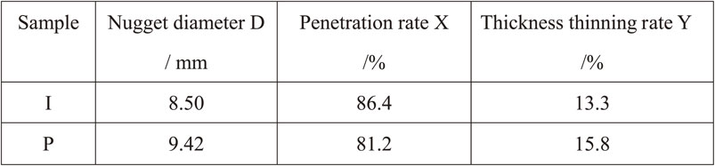
It can be seen from Table 4 that the nugget size of sample I is smaller than that of sample P. Nugget size is one of the most important control factors of state loading failure mode. The driving force of interface failure is the shear stress at the interface of two plates and that of pull-out fracture is the tensile stress around nugget. When the weld size is small and the shear stress reaches the critical value before the tensile stress, it will cause interfacial fracture. When the weld size is large, the resistance of nugget to interfacial damage will be increased, and the pull-out fracture will be caused.21) Meanwhile, compared with sample P, sample I has a higher penetration rate and a lower thinning rate. The penetration rate and thickness thinning rate are related to the heat input and deformation of materials under the high temperature. The heat input can be calculated by equation Q = I2Rt, in which Q is Joule heat, I is welding current, t is welding time and R is the resistance of the specimens. Sample I undergoes a shorter welding time under the condition of same welding current, so the Joule heat generated in Sample I is lower and then a smaller nugget forms in Sample I. It should be noted that the nugget size of both samples is larger than the criteria for qualification according to the plate thickness.
Moreover, a plastic deformation ring, which undergo the affection of heat and plastic deformation, forms before the formation of nugget and grows in a different rate with the nugget in RSW. When the generated heat is too high, nugget grows faster than plastic deformation ring, which leads to the increase of penetration rate and thickness thinning rate. Sample I undergoes a shorter welding time, so the deformation speed of the metal can not response timely, then sample I get a relatively lower thickness thinning rate.22) In addition, it should be pointed that the deformation of the metal produces warpage of two plates and then a distinct inclined angle at the faying face. In this paper, the inclined angle in sample P is slightly larger than that in sample I. The relationship between the inclined angle and the deformation is unclear.
3.4 Microhardness of spot welded jointsThe fracture mode and mechanical properties of RSW joint are affected by the hardness distribution in joint. Figure 5 shows the microhardness distribution in sample I and P.

Microhardness distribution in Sample I and Sample P.
It can be seen from Fig. 5 that there is no significan difference in the average hardness of fusion zone/nugget and raw material between sample I and sample P. The average value in FZ is 372 Hv and 254 Hv in sample I and that is 374 Hv and 246 Hv in sample P. However, two samples have a common phenomenon - softening in HAZ. The minimum hardness in sample I and sample P is 228 Hv and 224 Hv and the location falls into the critical zone. Advanced high strength steels have a higher carbon equivalence and higher hardness in BM and HAZ, which leads to a higher tendency to interfacial fracture.23) However, a softer HAZ helps to promote pullout failure.20) The main reason for the softening is that martensite suffers low temperature tempering in critical zone which leads to the decrease of hardness. Yinghao Yu et al. have found a “softening zone” appeared near the heat-affected zone near the base metal in dual-phase steel spot joints, and martensite tempering in critical zone is responsible for the softening.24)
In addition, it can be seen from Fig. 5 that the gradient of HAZ hardness in sample P is lower than that in sample I even the minimum hardness is similar in two samples. The reason can be explained by the high heat input produced in sample P and longer welding time for heat transfer. The lower hardness gradient is beneficial to impede the crack propagation and enhance the load-bearing capability.
3.5 Fatigue properties of RSW jointsIn low cycle fatigue test, the applied maximum force is 40% of the ultimate force in static tension-shear test and the stress ratio is 0.1, 40% of their static load-bearing capacity is chosen to investigate their dynamic load characteristics under their static load, that is similar working conditions for the bearing capacity of solder joints, rather than the same working conditions. For sample I, the applied force is 9.6 kN and the fracture cycle is 33080. For sample P, the applied force is 13.2 kN and the fracture cycle is 5855. It is obvious that the low cycle fatigue life of sample I is longer than that of sample P under the condition of 40% static load bearing capacity. It implies that the RSW joint which has high static load bearing capacity endures low fatigue life. The reason may be attributed to the unequal applied force and different macrostructure characteristics. The fatigue crack originates from tips at the faying surface of two plates for the stress concentration. The high inclined angle leads to high level of stress concentration and contribute to the nucleation of fatigue crack. It can be seen from Fig. 3(a) and Fig. 4(a) that the inclined angle in sample P is slightly larger than that in sample I.
To reveal the fatigue fracture characteristics of two samples, the fracture morphology is observed on SEM and the pictures are shown on Fig. 6–7.

Fatigue fracture morphology of sample I (a) overall appearance, (b) fatigue crack propagation region, (c) microcracks in crack propagation region, (d) dimples on the fracture surface.

Fatigue fracture morphology of sample P (a) overall appearance, (b) cracks on the fracture edge, (c) crack propagation region, (d) microcracks in crack propagation region.
It can be seen from Fig. 6(a) and Fig. 7(a) that the fracture morphology of RSW joint after low cycle fatigue test is similar to that of pull-out static fracture. Therefore, it is reasonable that the fatigue crack originates from the tip of the interface. However, typical fatigue crack growth region is found on both specimens (see Fig. 6(b) and Fig. 7(c)). At the same time, some microcracks are found in the crack growth zone (see Fig. 6(c) and Fig. 7(d)). In the fatigue fracture process of RSW joint, microcracks are produced under cyclic load and propagate through grain boundaries to form macro cracks. Microcracks grow slowly or even stop growth because of the different slip systems in adjacent grains. So, the softening of HAZ caused by martensite tempering is beneficial to improve fracture toughness and reduce fatigue damage. The fatigue steps in Fig. 6(b) and Fig. 6(c) show that there are multiple fatigue sources that are not in the same plane. In addition, some dimples are found on the fracture surface of sample I (see Fig. 6(d)) and no dimples are found in sample P. This phenomenon show that a large plastic strain occurs in sample I and no obvious strain occurs in sample P during fatigue. The applied force contributes to the strain and plastic deformation in fatigue samples.
Bin Liu25) studied the low cycle fatigue properties of high-strength hot-rolled dual-phase steel, and reported that the ferrite and martensite in the microstructure undergo elastic deformation during low-cycle fatigue. As the strain amplitude increases, the ferrite begins to plastically deform. However, due to the hard structure of martensite, the initial uniform plastic deformation of ferrite will be seriously hindered. As the number of strains increases, the inhibition of plastic deformation will lead to the hardening of the ferrite phase and the formation of non-uniform plastic deformation such as slip bands. Accumulated plastic deformation produces fatigue microcracks, which accumulate large cracks and eventually produce macroscopic fatigue cracks. The deformation of the ferrite was also observed in the sample I in the present study (see Fig. 6(c)), but was not clearly observed in the sample P. At the same time, many fatigue microcracks were observed and cumulative fatigue cracks were generated (see Fig. 6(c) and 7(d)). Explain that the results of the study are consistent with the results of this study. In addition, the cause of fatigue failure is due to the existence of a large number of dislocations at the ferrite/martensitic interface in the heat-affected zone. In the reciprocating loading process, a large number of dislocations hit the ferrite/martensitic interface, resulting in fatigue failure.26)
This work is supported by the Shanghai Science and Technology Committee (No. 2003 0500 900) and Shanghai University of Engineering Science (No. g202005001).