Abstract
An electrochemical surface treatment technique was developed in this study to improve the localized corrosion resistance of zirconium in a chloride ion environment. A combination of anodic and cathodic polarization cycles was applied to induce the selective dissolution of the inclusions that could potentially initiate the localized corrosion of zirconium. Shallow dips were observed on the specimen surface after the treatment, thereby indicating the dissolution of the inclusions. The electrochemical treatments via galvanostatic anodic polarization and potentiostatic cathodic polarization in concentrated phosphate-buffered saline resulted in a high pitting potential of greater than 2 V in a simulated body fluid. This indicated that the devised technique realized a significant increase in the localized corrosion resistance of the treated Zr.
This Paper was Originally Published in Japanese in Zairyo-to-Kankyo 69 (2020) 307–314. The captions of Figs. 2–14 and Table 1 are slightly modified.
1. Introduction
Metals are often utilized in devices for the reconstruction of motor and skeletal functions that are required for load-bearing capacity. This is because metals exhibit the optimal balance of strength and ductility, thereby resulting in high mechanical reliability.1–5) However, metals may become the sources of image distortion and signal loss or excess (known as artifacts) in the high-magnetic-field environment of magnetic resonance imaging (MRI), thereby preventing accurate diagnosis. These artifacts arise from the differences in the magnetic susceptibilities of biological tissues and metals.6–8) Therefore, it is necessary to decrease the magnetic susceptibility of the metals in implant devices to overcome the drawback of artifacts in MRI.
Zirconium (Zr) and titanium (Ti) belong to the same group in the periodic table; therefore, the mechanical and chemical properties of Zr are similar to those of Ti. Zr, which is categorized as a thermodynamically active metal, spontaneously forms a passive film on its surface, thereby resulting in high corrosion resistance. Therefore, Zr has been conventionally utilized in nuclear structural materials.9,10) Furthermore, Zr is considered a biosafe material because it is not cytotoxic. Zr is an attractive material for medical applications because it does not fuse with the contacting bone, unlike Ti, owing to its low reactivity with calcium ions.11–14) The magnetic susceptibility of Zr is significantly lower than that of other metallic biomaterials.15,16) It has been reported that the magnetic susceptibility of Zr is approximately 1/30th of that of type 316L stainless steel, approximately 1/7th of that of cobalt–chromium–molybdenum alloys, and approximately half of that of Ti and Ti alloys. Therefore, Zr is expected to be utilized in novel materials for MRI-compatible devices and retrievable implant devices after a long-term implantation.
The corrosion of metals results in degradation and fracture. The corrosion of biomaterials induces the fatigue, wear, and fretting of implanted devices, thereby causing serious harm to patients (e.g., metal allergy). Metals are not toxic and do not result in allergies or carcinogenesis. However, some of the metal ions that are released via the corrosion reaction of metallic implants form oxides, hydroxides, salts, and complexes. The interactions of these compounds with the autogenous biomolecules and cellular organs may induce the disruption of the regular biological functions, which is a major cause of toxic reactions.17,18) Therefore, the corrosion behavior of metallic biomaterials under the working environment must be subjected to rigorous evaluation, and it is necessary to simulate the corrosion behavior of biomaterials in practical use to ensure the biosafety.
Zr possesses high corrosion resistance in both acid and alkali solutions owing to the passive film on its surface. However, it is susceptible to localized corrosion by chloride ions.19–21) The concentration of chloride ions in a living body is always maintained at approximately 0.14 mol L−1 via physiological homeostasis. The implanted Zr will necessarily be in contact with the chloride ions in the body environment, and the use of inhibitors to prevent corrosion is inappropriate. Therefore, the biosafety of Zr can be evaluated by elucidating the mechanism of the localized corrosion in chloride-ion-containing solutions. There is limited research on the mechanism of the localized corrosion of Zr in chloride-containing environments. Therefore, the authors’ group has investigated the corrosion behavior of Zr in simulated body fluids. The pitting potential of Zr varies with the combination of alloying elements as well as the heat treatment conditions.22–25) Pitting corrosion is initiated on the inclusions that contain specific impurities such as tin and iron.26–29) Furthermore, the critical inclusions that cause pitting corrosion at lower applied potentials are infrequently exposed on the Zr surface. Furthermore, the exposure of these inclusions on the testing area that is subjected to the general electrochemical measurements is negligible. This induces substantial variations in the pitting potential.30) This research background indicates that the selective elimination of the corrosion-inducing inclusions will increase the localized corrosion resistance of Zr. Thus, novel electrochemical treatments comprising anodic and cathodic polarization cycles were developed in the present study to eliminate the inclusions on the Zr surface. The corrosion resistance of the Zr specimens, which were subjected to electrochemical treatments under various conditions, was evaluated using anodic polarization tests in a simulated body fluid.
2. Experimental Method
2.1 Specimen preparation
A pure Zr sheet (>99.5% grade; The Nilaco Corporation, Tokyo, Japan) of 100 mm × 100 mm × 10 mm was utilized in the present study. Table 1 shows the chemical composition of the material. The rolling direction (RD) is the most susceptible to localized corrosion. Therefore, the Zr sheet was cut into pieces of 10 mm × 10 mm × 1 mm to expose the surface that was perpendicular to the RD. The specimen surfaces were mechanically ground using #150, #320, #600, and #800 grit abrasive SiC papers. Subsequently, the specimens were ultrasonicated twice in acetone and once in isopropanol for 600 s each. A passive film was formed on the surface of the specimens immediately after polishing. The passive film grows owing to the contact with water during cleaning and drying as well as with atmospheric moisture during the storage in the desiccator. The growth of the passive film affects the corrosion potential before polarization and the shape of the initial response after polarization. Therefore, the specimens in the present study were immersed in ultrapure water for 24 h at room temperature after polishing. This ensured the growth of the passive film to a constant thickness, and the surface condition of the film was stabilized.

Table 1 Nominal composition of the pure Zr that is used in the present study.
Figure 1 shows a schematic illustration of the electrochemical surface treatment that was developed in the present study. The Zr surface contains numerous exposed inclusions. When Zr is anodically polarized over a certain potential in chloride-containing solutions, the local dissolution of one of the most soluble inclusions is initiated. This is accompanied by the dissolution of the surrounding matrix of the inclusion. When the applied potential is switched and the Zr specimen is cathodically polarized, the anodic reaction is electrochemically suppressed. This results in the inhibition of the dissolution reaction and the repassivation of the surface. The progress of the forced dissolution reaction via anodic polarization results in the expansion of the corrosion dip. When the dissolution dip expands to beyond a certain size, the inner inclusion is completely dissolved; alternatively, the inclusion loses the mechanical support from the contacting matrix and is released into the solution. This prevents the dissolution of the repassivated sites, even during the application of the anodic potential in subsequent steps. The multiple anodic and cathodic polarization cycles decrease the number of inclusions that are responsible for localized corrosion, and the repassivated dips remains on the Zr surface. Furthermore, the easily dissolved inclusions are highly likely to be removed, and the inclusions that are most probable to induce the corrosion of Zr are removed preferentially. Therefore, the devised electrochemical surface treatment comprising anodic and cathodic polarization cycles is expected to significantly improve the corrosion resistance of Zr.

The procedure of the electrochemical surface treatment that was applied in the present study is described as follows. A specimen holder that was composed of polytetrafluoroethylene (PTFE) and an acrylic resin31) was utilized as the working electrode. The Zr specimen and an O-ring were fixed in the holder. The testing area was 0.353 cm2 (diameter: 6.70 mm). A Pt plate and a saturated calomel electrode (SCE) were used as the counter and the reference electrodes, respectively. The electrochemical surface treatments were performed using either a potentiostat (HABF-501A, Hokuto Denko Corporation, Tokyo, Japan) that was connected to a function generator (HB-111, Hokuto Denko Corporation, Tokyo, Japan) or an electrochemical measurement system (IviumStat, Ivium Technologies B.V., Eindhoven, The Netherlands). The Zr specimens were polarized under either potentiodynamic conditions or a combination of potentiostatic and galvanostatic conditions at room temperature. The Zr specimens were ultrasonicated in acetone for 600 s after the electrochemical treatment. Thereafter, the surface observations and profile analyses were performed using three-dimensional optical and laser microscope (OM/LM; LEXT OLS4000, Olympus Corporation, Tokyo, Japan).
2.3 Evaluation of corrosion resistance
The corrosion resistance of the electrochemically treated and untreated Zr specimens was evaluated using anodic polarization tests that were conducted according to the Japanese standard testing method, JIS T0302. The equipment and electrodes that were used for the determination of the corrosion resistance were identical to those described in “2.2 Surface treatment”. The test solution was physiological saline (0.9 mass% aqueous solution of NaCl) that is one of a simulated body fluid. The solution temperature was 310 K. The final value of the open-circuit potential after 600 s of immersion in the solution was denoted as the corrosion potential (Ecorr). A potential was applied at −100 mV from the corrosion potential, and a linearly increasing anodic potential scan of 1 mV s−1 was initiated. There was a rapid increase in the current owing to pitting corrosion occurrence. When the current density reached 10 mA cm−2, the measurements were finished. The tests were repeated five times under the same conditions to evaluate the reproducibility. The pitting potential (Epit) was determined from the polarization curve. It was defined as the final potential at which the current density exceeded 100 µA cm−2, and the measurement was performed according to the standard method, JIS G0577. Each value of the pitting potential (n = 5) was statistically evaluated using the Student’s t-test with a significance of p < 0.05. Thus, the variation in the pitting potentials for the specimens with and without the surface treatments was determined.
3. Results and Discussion
3.1 Electrochemical treatments under potentiodynamic controls in a corrosive solution
The corrosion resistance of stainless steels, which are the conventional passivation-type materials, is lower than that of Zr. Therefore, a 10 mass% aqueous solution of FeCl3, which is corrosive for stainless steels, was used as the treatment solution in the present study. The repassivation behavior of Zr in the FeCl3 solution was evaluated in advance to determine the treatment conditions. Initially, the potential was swept at a constant rate of 20 mV min−1 toward the positive direction. Subsequently, the potential was maintained for 0 or 300 s immediately after the current density reached 1 mA cm−2 to control the degree of propagation of the initiated corrosion dip. Thereafter, the potential was again swept at a constant rate of 20 mV min−1 toward the negative direction until complete repassivation occurred. The results of the cyclic polarization measurements are shown in Fig. 2. Both the specimens underwent pitting corrosion at approximately 1.0 V. The current density exhibited a typical hysteresis shape that implied the occurrence of localized corrosion. The current density decreased rapidly with the decrease in the potential to 0.1 V. Thereafter, the anodic current was changed to a cathodic current at approximately 0 V. Both the specimens exhibited approximately identical behaviors during the reverse potential sweep. The results confirmed that Zr was repassivated at less than 0.1 V in the 10 mass% aqueous solution of FeCl3, regardless of the pit size.

The first electrochemical treatment condition was devised based on the aforementioned results. The lower limit potential was required to be lower than the repassivation potential, which is presented in Fig. 2, and higher than the plating potential from Fe ions in the solution to metallic Fe. Therefore, the lower limit potential was set to −0.3 V. The upper limit potential, at which Zr underwent pitting corrosion, was set to 1.0 V. The potential sweep rate was 100 mV s−1, and the positive/negative scan was repeated for 100 cycles. Hereafter, this treatment condition will be referred to as condition A. Figure 3 shows the cyclic voltammogram that was obtained during the electrochemical treatment under condition A. The current density increased significantly at just below the upper limit potential during the anodic polarization in the initial cycles, thereby presenting hysteresis curves. The current density near the lower limit potential in all the cycles was measured to be −0.03 A cm−2, and this was attributed to the evolution of H2 gas. A temporal increase in the current was occasionally observed, such as in the 10th anodic cycle at approximately 0.3 V (Fig. 3). This might have been induced by the temporal localized corrosion that was triggered by the dissolution of inclusions. The peak anodic current decreased with the increase in the number of cycles. This was attributed to the increase in the thickness of the passive film that exhibited semiconducting electric properties. Therefore, the upper limit potential was modified to address the decrease in the treatment efficacy owing to the growth of the passive film. The upper limit potential was increased with steps of 0.2 V, i.e., 1.0, 1.2, 1.4, 1.6, and 1.8 V, every 20 cycles. This treatment condition is hereafter referred to as condition B. Figure 4 shows the cyclic voltammogram that was obtained during the electrochemical treatment under condition B. The peak anodic current increased immediately after the increase in the upper limit potential and decreased with the increase in the temporary-fixed potential cycles. There was a temporary increase in the current at approximately 0.3 V from the 81st to 100th cycles. A temporal current increase, such as that observed in condition A (Fig. 3, 10th cycle). Generally, inclusions are of diverse compositions and sizes, and each inclusion shows a unique dissolution potential. The inclusions that were difficult to dissolve at a low applied potential step were eliminated by the increase in the upper limit potential.

Figure 5 shows the low-magnification OM image of the electrochemically treated Zr surface under condition A. Several black dots (arrows in Fig. 5) were observed on the surface. Figure 6 shows the high-magnification LM image and three-dimensional profile image of the area around the typical black dot shown in Fig. 5. The micron-scale hemispherical dip, with a width and depth of approximately 25 and 15 µm, respectively, indicated a trace of the dissolved inclusion.


Figure 7 shows the polarization curves of the electrochemically treated Zr specimens under conditions A and B in physiological saline. The polarization curves of the untreated Zr are overlaid as broken gray lines. The pitting potential of the untreated Zr varied from 0.5 to 1.2 V. This result indicated the substantial variation in the corrosion-inducing properties of the inclusions that trigger pitting corrosion.27,28) The electrochemically treated Zr specimens exhibited an extended passive region. The pitting potentials of all the treated Zr specimens were higher than 1 V. Therefore, the inclusions that induce pitting corrosion at relatively lower applied potentials were dissolved and eliminated via the electrochemical treatment. However, the potential at which the electrochemically treated Zr under condition B underwent pitting corrosion was lower than the maximum applied potential (1.8 V) for this treatment. Furthermore, it was approximately identical to that for the electrochemical treatment under condition A. The results revealed that the electrochemical treatment under condition B did not result in the complete dissolution of the inclusions that induce pitting corrosion at an applied potential of 1 V or higher. Consequently, the unreacted inclusions remained on the specimen surface after the treatment, and the pitting potential was lower than the maximum applied potential (1.8 V) for the treatment.

The previously determined results indicated that the anodic and cathodic polarization cycles improved the localized corrosion resistance of Zr to a certain extent. A slow potential sweep was desirable during anodic polarization for the formation of a small corrosion dip and the elimination of inclusions. Conversely, a fast potential sweep was desirable during cathodic polarization for immediate repassivation and the suppression of the excessive expansion of the dip. Hence, the modification of the treatment conditions was investigated, and a combination of galvanostatic anodic polarization and potentiostatic cathodic polarization was considered. Galvanostatic anodic polarization facilitates the autonomous adjustment of the applied potential to the optimal level for the dissolution of inclusions; additionally, the expansion rate of the dip is controlled via a constant current condition at the start of the dissolution reaction. In addition, potentiostatic cathodic polarization enables the surface condition to immediately reach the repassivation state.
The modification of the treatment conditions also prevents the occurrence of undesirable cathodic reactions at an inappropriate potential. Phosphate-buffered saline (PBS; T9181, Takara Bio Inc., Shiga, Japan) was used as the treatment solution in the present study. PBS is often utilized for biological experiments both in vitro and in vivo. It contains chloride ions and exhibits not only strong neutral buffering capacity (pH around 7.4) but also excellent biosafety. The reactions for repassivation and inclusion dissolution proceeds rapidly in PBS in response to the applied anodic current and cathodic potential, respectively. Table 2 shows the composition and pH of the PBS used in the present study. The Zr specimen was anodically polarized with a constant current of 50 µA for 10 s; subsequently, it was cathodically polarized with a constant potential of −2 V for 30 s. The electrochemical treatments with the combination of anodic and cathodic polarization were repeated for 100 cycles (condition C) and 200 cycles (condition D).

Table 2 Chemical composition of the PBS.
Figure 8 shows the variation in the potential during the galvanostatic anodic polarization steps of the electrochemical treatment under condition C. The potential exhibited apparent behavioral variations during the early, middle, and late stages of the treatment. It increased with the increase in the number of cycles from the 1st to 15th cycle. The thickness of the passive film increased with anodization, and this resulted in the increase in the electric resistance because Zr is a typical valve metal. The potential dropped after 7 s from the switch to anodic polarization in the 16th cycle. Thereafter, the waiting time until the potential drop decreased (Fig. 8(b)). The potential remained higher than 1.5 V immediately following the switch to anodic polarization after the 31st cycle; however, it dropped to 0.3 V within a few seconds. The potential drop during galvanostatic anodic polarization indicated the dissolution of inclusions. The continuous increase in the applied potential until a certain number of cycles owing to the anodic oxidation reaction was necessary for promoting the dissolution of inclusions. The dips were repassivated during the potentiostatic cathodic polarization for 30 s. The beginning of the ensuing high potentials (>1.5 V) at anodic polarization steps confirmed the passive state of Zr.

Figure 9 shows the polarization curves of the electrochemically treated Zr specimens under conditions C and D in physiological saline. The average pitting potentials for both the specimens was approximately 1.7 V. This was not only significantly higher than the pitting potential of the untreated Zr but also higher than the pitting potential of the electrochemically treated Zr under the potentiodynamic controls in FeCl3 (conditions A and B, Fig. 7). The results indicated the increase in the localized corrosion resistance of Zr via the electrochemical treatment with a combination of galvanostatic anodic polarization and potentiostatic cathodic polarization in PBS. However, the pitting potential of the electrochemically treated Zr under condition D (200 cycles) was approximately identical to that of the electrochemically treated Zr under condition C (100 cycles). One of the specimens under condition D exhibited a low pitting potential of 1.2 V, despite its treatment for 100 cycles more than that for the specimens under condition C. This indicated that the electrochemical treatment under condition D was insufficient for the complete elimination of the inclusions that easily induce pitting corrosion. Therefore, the increase in the number of cycles under condition D as compared to that under condition C did not result in an additional increase in the localized corrosion resistance.

The results indicated that the electrochemical treatments under the galvanostatic and potentiostatic controls in PBS effectively improved the localized corrosion resistance of Zr. Subsequently, the measures to optimize the type of solution and the electrolytic conditions were investigated. It was expected that a high concentration of chloride ions in the electrolyte during galvanostatic anodic polarization would facilitate the effective elimination of the corrosion-inducing inclusions. Furthermore, it was expected that the increase in the buffering ability of PBS would result in the immediate repassivation of the dissolution reaction around the dip. Therefore, three-times-concentrated PBS (3×PBS) was prepared for the electrochemical treatment. The Zr specimen was subjected to anodic polarization with a constant current of 50 µA for 10 s. Subsequently, it was subjected to cathodic polarization with a constant potential of −2 V for 30 s. The anodic and cathodic polarization steps were repeated for 100 cycles (condition E). Additionally, a new condition to suppress the excessive expansion of the dip during anodic polarization was investigated. The galvanostatic anodic polarization up to at least 20 cycles induced an increase in the potential owing to the anodization effect; however, it did not affect the dissolution of inclusions. Therefore, the anodic polarization time from the 21st cycle was decreased from 10 to 3 s (condition F).
Figure 10 shows the polarization curves of the electrochemically treated Zr specimens under conditions E and F in physiological saline. The pitting potential of all the treated Zr specimens under condition E was higher than 2 V. This indicated that the increase in the concentration of chloride ions and the buffering capacity of the phosphate-ion series increased the efficacy of the electrochemical treatment. The authors’ group investigated the relationship between the inclusions and the pitting corrosion of Zr using micron-scale electrochemical measurements. The numerous non-critical Fe-rich inclusions on the pure Zr surface trigger pitting corrosion under high applied potentials of more than 2 V.28,32) The pitting potentials of more than 2 V under condition E indicated the elimination of all the critical inclusions via the electrochemical treatment. However, the electrochemically treated Zr specimens under condition F occasionally underwent pitting corrosion at relatively low potentials of 1.4 and 1.8 V. The treatment efficiency per cycle under condition F was lowered possibly because the dissolution and release of the inclusions remained incomplete owing to the short anodic polarization time.

Figure 11 shows the low-magnification OM image of the electrochemically treated Zr surface under condition E. The presence of numerous black dots along with an interference-colored area around the dots was observed. Figure 12 shows the high-magnification LM image and three-dimensional profile image of the area around one of the black dots shown in Fig. 11. The numerous dots in Fig. 11 represented a micron-scale dip. This dip indicated a trace of the dissolved inclusion, similar to that shown in Figs. 5 and 6. The width of the dip (30 µm) under condition E was equivalent to that of the dip under condition A. The depth of the dip (about 10 µm) under condition E was lower than that of the dip under condition A. The anodic reaction rate was effectively controlled under the constant current condition. The Zr ions that were produced from the anodic reaction site diffused into the surrounding matrix. Subsequently, corrosion products such as Zr oxide and hydroxide were formed owing to the significant increase in the pH that was induced by the strong buffering ability of PBS. The interference-colored areas around the dips might have originated from the deposition of the corrosion products.


Dips were formed owing to the electrochemical treatment, and they were distributed throughout the surface. Therefore, the individual inclusions that were distributed on the specimen surface were eliminated in each treatment cycle. Sixty-one dips, with a surface area of 0.065 cm2, were observed in Fig. 11. The total treatment area of the Zr specimen was 0.353 cm2. Therefore, the number of eliminated inclusions on the entire treated surface area was estimated to be 330, which was higher than the number of the combination of anodic and cathodic polarizations (100 cycles). This indicated the elimination of multiple inclusions in a single polarization cycle. Figure 13 shows the high-magnification LM image and three-dimensional profile image of the area around the trace of a dissolved inclusion on the electrochemically treated Zr under condition F. The electrochemical treatment under condition F, where the anodic polarization time was decreased from 10 to 3 s, induced the formation of a significantly smaller dip as compared to that formed via the electrochemical treatment under condition E. The average width and depth of the dip were approximately 8 µm and 3 µm, respectively. The expansion of the dip and the simultaneous dissolution of the surrounding matrix were minimized owing to the optimization of the electrochemical treatment conditions. If relatively larger dips around 10 µm in depth will become problem such as fatigue fracture or stress corrosion cracking, the decrease of the anodic polarization time will be effective as in Condition F. However, the effect of the demonstrated electrochemical treatment on the fatigue fracture and the stress corrosion cracking should be elucidated by further investigations.

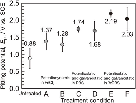
Figure 14 shows the summary of the pitting potentials of the electrochemically treated Zr specimens under each condition in the present study. Zr was susceptible to localized corrosion by chloride ions, and the pitting potential in the chloride-containing environments exhibited significant variations. Despite the high corrosion resistance of Zr, the application of Zr as biomaterials requires careful consideration. The critical inclusions, which induce pitting corrosion at the same level as stainless steel, are infrequently exposed on the Zr surface. However, they are the dominant factor that determine the localized corrosion resistance of Zr. The inclusions that trigger pitting corrosion at low potentials were eliminated via the electrochemical treatments comprising anodic and cathodic polarization cycles. This resulted in a substantial increase in the pitting corrosion resistance of Zr, and extremely high pitting potentials of more than 2 V were obtained. Furthermore, the variability of the pitting potential was suppressed. The demonstrated technique in the present study is expected to increase the reliability of Zr, thereby widening the range of applications of Zr.
4. Conclusion
The present study demonstrated the electrochemical treatments comprising anodic and cathodic polarization cycles for the dissolution of the exposed inclusions on the Zr surface. Shallow dips, which were the traces of inclusion dissolution and were subsequently repassivated, were observed on the Zr surface after the electrochemical treatment. The electrochemical treatments were performed under potentiodynamic controls in a corrosive solution or under a combination of galvanostatic and potentiostatic controls in a neutral buffer solution. The results revealed the high pitting potentials of Zr in physiological saline. The electrochemical pretreatment that induced the dissolution of inclusions increased the localized corrosion resistance of Zr. The Zr specimen that was subjected to the polarization cycles under a combination of the galvanostatic and potentiostatic controls in concentrated PBS exhibited a constant pitting potential of greater than 2 V. Furthermore, the adjustment of the treatment conditions limited the size of the dip that was necessarily formed after the treatment to a minimum of within 10 µm in depth.
REFERENCES
- 1) T. Hanawa and T. Yoneyama: Kinzoku-Biomaterial, (Corona-sha, Tokyo, 2010) pp. 1–9.
- 2) C. Oldani and A. Dominguez: Recent Advances in Arthroplasty, (Intech Open, London, 2012) pp. 149–162.
- 3) D. Duraccio, F. Mussano and M.G. Faga: J. Mater. Sci. 50 (2015) 4779–4812.
- 4) T. Hanawa: Front. Bioeng. Biotechnol. 7 (2019) 170.
- 5) F.H. Froes and M. Qian: Titanium in Medical and Dental Applications 1st Ed., (ELSEVIER, Amsterdam, 2018) pp. 95–113.
- 6) The Japan Institute of Metals and Materials: The Advanced Research of Biomaterials, (Maruzen, Tokyo, 2014) pp. 115–124.
- 7) J.S. Suh, E.K. Jeong, K.H. Shin, J.H. Cho, J.B. Na, D.H. Kim and C.D. Han: Am. J. Roentgenol. 171 (1998) 1207–1213.
- 8) S.P. Hong, Y.M. Ko and C.S. Kim: Mater. Trans. 55 (2014) 1634–1636.
- 9) C. Kajizaki: J. JILM 1956 (1956) 106–117.
- 10) R. Krishnan and M.K. Asundi: Proc. Indian Acad. Sci. (Engg. Sci.) 4 (1981) 41–56.
- 11) E. Kobayashi, M. Ando, Y. Tsutsumi, H. Doi, T. Yoneyama, M. Kobayashi and T. Hanawa: Mater. Trans. 48 (2007) 301–306.
- 12) T. Hanawa: Zairyo-to-Kankyo 66 (2017) 381–387.
- 13) Y. Tsutsumi, D. Nishimura, H. Doi, N. Nomura and T. Hanawa: Mat. Sci. Eng. C 29 (2009) 1702–1708.
- 14) T. Hanawa: J. JILM 62 (2012) 285–290.
- 15) N. Nomura, Y. Tanaka, Suyalatu, R. Kondo, H. Doi, Y. Tsutsumi and T. Hanawa: Mater. Trans. 50 (2009) 2466–2472.
- 16) Y. Kajima, A. Takaichi, T. Yasue, H. Doi, H. Takahashi, T. Hanawa and N. Wakabayashi: J. Mech. Behav. Biomed. Mater. 53 (2016) 131–141.
- 17) Q. Chen and G.A. Thouas: Mater. Sci. Eng. R 87 (2015) 1–57.
- 18) M. Geetha, A.K. Singh, R. Asokamani and A.K. Gogia: Prog. Mater. Sci. 54 (2009) 397–425.
- 19) S. Hornkjøl: Electrochim. Acta 33 (1988) 289–292.
- 20) G.C. Palit and H.S. Gadiyar: Corrosion 43 (1987) 140–148.
- 21) J.S. Chen, A. Bronson and D.R. Knittel: Corrosion 41 (1985) 438–445.
- 22) Y. Tsutsumi: Zairyo-to-Kankyo 63 (2014) 360–364.
- 23) Y. Tsutsumi: Proc. 181st Symposium, (JSCE, 2014) pp. 66–73.
- 24) Y. Tsutsumi: Proc. 175th Symposium, (JSCE, 2012) pp. 9–14.
- 25) Y. Takano, Y. Tsutsumi, H. Doi, N. Nomura, K. Noda and T. Hanawa: Collected Abstracts of the Proc. 55th Jpn. Conf. Materials and Environments, (JSCE, 2008) pp. 177–178.
- 26) S. Nakano, Y. Tsutsumi, H. Doi, M. Shimojo, K. Noda and T. Hanawa: Collected Abstracts of the Proc. 60th Jpn. Conf. Materials and Environments, (JSCE, 2013) pp. 241–242.
- 27) Y. Tsutsumi, S. Nakano, Y. Sugawara, M. Ashida, P. Chen, H. Doi, M. Shimojo, I. Muto, N. Hara and T. Hanawa: Collected Abstracts of the 2015 Autumn Meeting of Japan Inst. Met. Mater., (2015) p. 6.
- 28) J. Tsukada, Y. Tsutsumi, M. Ashida, P. Chen, H. Doi, Y. Sugawara, I. Muto, N. Hara and T. Hanawa: Collected Abstracts of the 2016 Autumn Meeting of Japan Inst. Met. Mater., (2016) p. 256.
- 29) T. Manaka, Y. Tsutsumi, M. Ashida, P. Chen and T. Hanawa: Collected Abstracts of the 2019 Autumn Meeting of Japan Inst. Met. Mater., (2019) p. 475.
- 30) J. Tsukada, Y. Tsutsumi, M. Ashida, P. Chen, H. Doi, Y. Sugawara, I. Muto, N. Hara and T. Hanawa: Collected Abstracts of the 2016 Spring Meeting of Japan Inst. Met. Mater., (2016) p. 305.
- 31) Y. Tanaka, E. Kobayashi, S. Hiromoto, K. Asami, H. Imai and T. Hanawa: J. Mater. Sci. Mater. Med. 18 (2007) 797–806.
- 32) Y. Tsutsumi, I. Muto, S. Nakano, J. Tsukada, T. Manaka, P. Chen, M. Ashida, Y. Sugawara, M. Shimojo, N. Hara, H. Katayama and T. Hanawa: J. Electrochem. Soc. 167 (2020) 141507.


