Abstract
Corrosion resistance of carbon steel covered with resin coating containing nickel sulfate has been evaluated under chloride and sulfuric acid mist environment. The structure of corrosion products formed on steel surface was investigated by XRD and XAFS analyses using synchrotron radiation. Nickel sulfate promoted the formation of goethite and akaganeite. It was considered that this akaganeite was not tetragonal β-FeOOH but monoclinic akaganeite containing nickel.
This Paper was Originally Published in Japanese in Zairyo-to-Kankyo 69 (2020) 148–153.
1. Introduction
Steel is one of the indispensable materials for major infrastructures due to its superior strength, ductility, and workability. Therefore, it has been widely used in various fields since the period of high economic growth of 1960’s in Japan. However, the degradation of steel infrastructure due to corrosion has been considered as a pressing issue to be solved because steel is prone to corrode under the presence of H2O, O2 and Cl−.
Acidic environments consisting of sulfuric acid mist are established in exhaust gas treatment facilities of fired power plant as a result of the condensation of combustion gases containing sulfur compounds and chlorides generated from fossil fuel. This results in more severe corrosion than in neutral environments.1) Therefore, stainless steels or low alloy steels that exhibit reasonable corrosion resistance in environments with sulfur compounds are presently used in such facilities. However, the corrosion loss of the steels in such environments is often reported to reach several hundred µm;2) thus, the development of more corrosion resistant steels is required.
Once steels corrode, their surfaces are covered with rusts that consist of oxide and hydroxide. In general, such rusts are not protective against further corrosion; however, the modification of their structures can significantly improve the protectiveness of the rusts. The authors found that the carbon steel covered with a resin containing a metallic salt forms rusts with an enhanced protectiveness, including a metallic cation derived from the salt.3) This finding implies that carbon steel can form similar protective rusts even in the severe acidic environments described above when modified by the metallic cation.
The present work aims at evaluating corrosion resistance of carbon steel covered with a resin coating containing NiSO4 in a severe acidic environment and revealing the structure of the rust grown in this environment.
2. Experimental
2.1 Corrosion test
The specimen used was a polished plate of SPCC-SB carbon steel with the dimension of 30 × 25 × 2 mm3, whose surface was covered with a NiSO4-added resin coating with the average thickness of approximately 100 µm. A corresponding carbon steel specimen without the resin coating was also used as a reference. The chemical composition of the carbon steel is listed in Table 1. The resin coating was prepared by mixing butyral resin with some solvent and NiSO4 powder (particle size less than 30 µm) in the volume ratio of 5:1. The concentration of NiSO4 in the resin coating was calculated as 2.13 mol L−1.

Table 1 Chemical composition of carbon steel (mass%).
During the corrosion test that simulated a sulfuric acid environment, both specimens were placed in the chamber where the temperature and the relative humidity were controlled at 65°C and 70%, respectively, and approximately 1 mL of a test solution (H2SO4 + 10 g L−1 NaCl, pH 3) was sprayed onto a surface of the specimens twice a day with an interval of approximately 7 h. The corrosion test was carried out for 6 weeks, in which the spraying of the solution was performed 60 times.
2.2 Surface observation and corrosion loss evaluation
Rusts formed on the specimens was observed via a digital microscope. The corrosion loss was evaluated by the difference in weight of the substrate steels before and after the corrosion test. Note that the rusts formed on the carbon steels were removed by an organic solvent and a derusting liquid.
2.3 Structural analysis of rust
The constituents and structures of rusts formed on the specimens were characterized by X-ray diffraction (XRD) and X-ray absorption fine structure (XAFS) analyses. As rusts that contain metallic cations typically consist of fine crystals,4–7) highly brilliant synchrotron radiation was used for the characterizations.
XRD measurements were performed at BL16XU of SPring-8 for rusts grown in the sulfuric acid mist environment on the carbon steels with and without the NiSO4-added resin coating. Note that the rusts were removed from the steel specimens and then were powdered prior to the characterizations. To suppress the background signal due to X-ray fluorescence from Fe and Ni, the energy of X-ray was controlled at 15 keV (corresponding wavelength of 0.827 Å). Monochromatic X-ray obtained via a Si(111) double crystal monochromator was irradiated on the powdered rusts at the incident angle of 2°. The resulting diffracted X-rays were detected in the 2θ range of 5° and 35°. The size of the incident X-ray was defined at 0.1 (height) × 1.0 (width) mm2 through a 4-quadrant slit, whereas two different slits of 0.1 (height) × 1.5 (width) mm2 and 0.2 (height) × 2.0 (width) mm2 were used as the receiving slit.
In addition, XAFS measurements were carried out at BL16B2 of SPring-8 to examine local structures around Fe and Ni atoms in the rusts. After the optimization of the degree of X-ray absorption, μt, measurements of Fe-K and Ni-K absorption edges were conducted for the powdered rusts in the transmission mode using the monochromatic X-ray beam from the double crystal monochromator. The same measurements were carried out for the reference powders as a comparison. Fe3O4 and α-FeOOH, detected by XRD, as well as NiO and Ni(OH)2, assumed from the possible chemical state of Ni in this environment, were used as reference samples.
3. Results
3.1 Surface appearance and corrosion loss
Figure 1 shows the surface appearance of the specimens before and after the corrosion test. The surface without the coating was severely corroded, and primarily black and dark brown rusts were formed. Less corrosion was observed on the surface covered with the coating even after the corrosion test, although the growth of dark brown rusts was confirmed. The weight loss caused by the corrosion test is summarized in Fig. 2. As presented in the figure, the corrosion became approximately 1/28 in the case of the steel surface covered with the coating, compared to that on the steel surface without the coating.
3.2 XRD
XRD patterns obtained for rusts grown on the specimen surfaces after the corrosion test are presented in Fig. 3. Peaks in the figure were normalized for comparison by the peak height generated at 2θ = 18.80°, which is the Fe3O4 (311) peak. For the specimen without the resin coating, peaks identified as magnetite (Fe3O4), goethite (α-FeOOH), akaganeite (β-FeOOH), and lepidocrocite (γ-FeOOH) were detected, while for the specimen covered with the NiSO4-added resin coating, magnesite, goethite, and akaganeite were obtained. Note that peaks derived from nickel compounds were not detected for the rust grown on the carbon steel covered with the NiSO4-added resin coating.

The peak height ratio of goethite to magnetite increased on the specimen covered with the resin coating; the peak height ratio of goethite (110) at 11.36° to magnetite (311) at 18.80° was 0.35 for the specimen without the resin coating, whereas the counterpart for the specimen covered with the NiSO4-added resin coating was 0.51. In addition, a peak derived from akaganeite (101) and $(10\bar{1})$ was determined at 6.37° for the specimen without the coating. The corresponding peak for the specimen covered with the coating was obviously larger than that for the non-coated specimen, and split into two peaks at 6.22° and 6.37° as presented in the inset figures. Similarly, a peak from akaganeite (200) and (002) appeared at 9.01° for the specimen without the coating, whereas the peak was split into two peaks at 8.57° and 9.01° for the specimen covered with the NiSO4-added resin coating.
3.3 XAFS
Figure 4(a) shows Fe-K X-ray absorption near edge structure (XANES) spectra obtained from the rusts on the specimens after the corrosion test. The spectra obtained from the references (goethite and magnetite) were also included for comparison. In the present work, absorption edges were determined as the X-ray energy, where μt equals to 0.5 in the spectra, and they are marked by arrows in the figure. It is often reported that the absorption edge in the XANES spectrum is likely to be shifted to a higher energy region with an increase in the oxidation number of elements.8–10) This was confirmed by the spectra of the references in Fig. 4(a), as the absorption edge of goethite in which the oxidation number of Fe is larger compared to magnetite was shifted to the higher energy region. As presented in Fig. 4(a), the absorption edge obtained for the carbon steel covered with the NiSO4-added resin coating was located in the higher energy region compared to that obtained for the carbon steel without the resin coating. This finding indicates that the average oxidation number of iron compounds formed on the steel with the NiSO4-added resin coating was larger; the fraction of iron oxyhydroxide was larger than magnetite. Figure 4(b) presents the radial distribution function (RDF) around the Fe atoms. A peak derived from the F–O bond was observed near 1.0∼2.0 Å in the RDF for the both specimens with and without the NiSO4-added resin coating. The peak indicates that the tetrahedral FeO4 and octahedral FeO6 units were present in rust layers on the steels. In the RDF of magnetite, peaks with the similar height, derived from Fe–Fe bond, were observed at approximately 2.6 Å and 3.1 Å as a double peak, whereas in the RDF of goethite, a peak appears at approximately 2.6 Å, but no peak was observed at approximately 3.1 Å. This double peak is attributed to the spinel structure of magnetite. More precisely, two different distances between Fe atoms were constructed in magnetite as the Fe atom was located in the center of the tetrahedron unit, as well as the octahedron unit. In the case of the carbon steels after the corrosion test, the double peak was observed, although the peak at approximately 3.1 Å was higher on the steel without the resin coating. This implies that the fraction of magnetite in the iron compounds is larger on the carbon steel without the coating, which is in accordance with the explanation regarding the XANES spectrum.
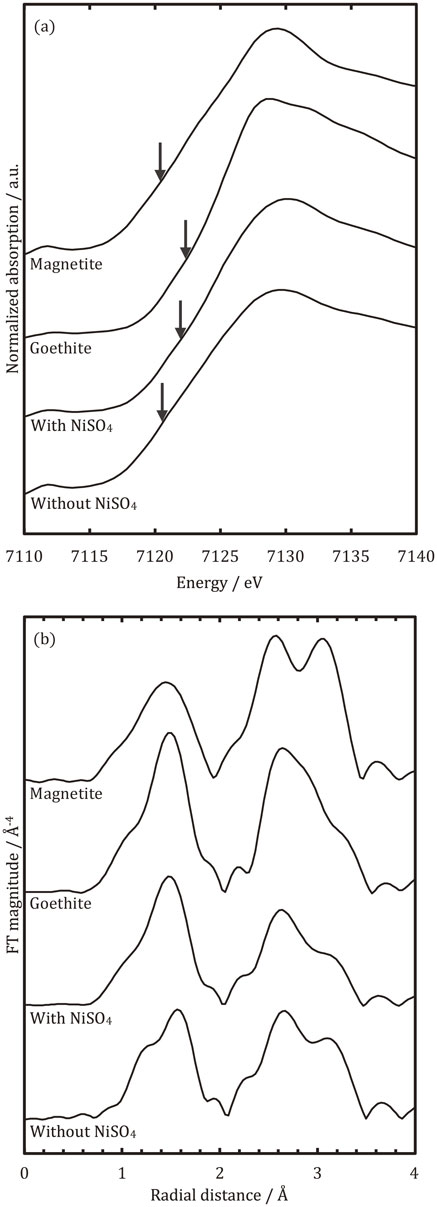
Figure 5(a) presents the Ni-K XANES spectra obtained from the rust grown on the NiSO4-added resin-coated specimen after the corrosion test. Spectra obtained from the references (NiO and Ni(OH)2) are also included for comparison. Similar to the XANES spectra shown in Fig. 4(a), the absorption edges are indicated by arrows (see, Fig. 5(a)). The absorption edge of the rust is almost identical to those from the references, indicating that the oxidation number of Ni in the rust layer is 2. In the RDF, a peak derived from Ni–O bond was observed at 1.6 Å for the specimen and the references. The peak also demonstrates the presence of an octahedral NiO6 unit in the structure of the rust. On the other hand, the peak from the Ni–Ni bond appears at different distances as shown in Fig. 5(b); the peak is found at approximately 2.5 Å for the NiO reference, but at approximately 2.7 Å for the Ni(OH)2 reference and the rust formed on the NiSO4-added resin-coated specimen, indicating that Ni2+ is found to be coordinated with OH− rather than O2−.

4. Discussion
4.1 Rusts formed on carbon steel in a sulfuric acid mist environment containing chlorides
The present section discusses the structure of rust formed on carbon steel under the sulfuric acid mist environment containing chlorides, and the effects of NiSO4-added resin coating on the structure of the rust.
The results obtained by XRD and XAFS measurements indicate that the rust formed on bare carbon steel after the corrosion test in the sulfuric acid mist environment containing chlorides mainly consists of magnetite. This finding differs from the well-known findings in neutral atmospheric environments where rusts on carbon steel are mainly composed of iron oxyhydroxides. The difference in the main component of the rust can be attributed to the different rate of oxidation reaction of Fe2+ between neutral atmospheric environments and the sulfuric acid mist environment, that is, it is considered that the oxyhydroxides in which the oxidation number of Fe is 3 are likely to grow when the oxidation reaction rate of Fe2+ is relatively fast. On the other hand, when the oxidation reaction rate is slow, the magnetite in which the oxidation number ranges from 2 to 3 is prone to grow. The oxidation reaction rate of Fe2+ can be expressed as follows:11,12)
| \begin{equation}
- \frac{d[\textit{Fe}^{2+}]}{dt} = k[\textit{Fe}^{2+}]p_{O_{2}}[\textit{OH}^{-}]^{2}
\end{equation}
| (1) |
The concentration of OH
− is relatively small in the sulfuric acid mist environment, compared to neutral atmospheric environments. In addition, in the mist environment, the rust formed on carbon steel is covered with a thick liquid film of the acid throughout the whole duration of the corrosion because the drying process is not established during the corrosion, different from atmospheric corrosion in neutral environments where the wet process and the drying process are repeated. The diffusion of O
2 to the substrate surface is suppressed in the thick liquid layer, lowering the activity of O
2 in the rust. Therefore, the smaller concentration of OH
− and the lowered activity of O
2 could result in the suppressed oxidation reaction of Fe
2+ in the mist environment, compared to neutral environments.
The fraction of structural isomers of oxyhydroxide grown on carbon steel in the sulfuric acid mist environment varied when the carbon steel surface was covered with the NiSO4-added resin coating as demonstrated by XRD. That is, peaks derived from lepidocrocite were detected on carbon steel without the resin coating after the corrosion test, whereas no peaks from lepidocrocite was recognized from the rust grown on the carbon steel covered with the NiSO4-added resin coating. On the other hand, the peaks from goethite became larger, compared to those observed on the carbon steel without the resin coating. This can be due to the effects of SO42−. Sudakar et al.13) demonstrated that SO42− lowers the structural stability of lepidocrocite. In addition, Cornell et al.14) and Tamura et al.15) reported that SO42− facilitates the formation of goethite. In the present study, SO42− concentration in the rust grown on the carbon steel covered with the NiSO4-added resin coating is estimated beyond 5 × 10⁻⁴ mol/L, based on the amount of SO42− in the coating and the SO42− concentration of the test solution used to simulate the sulfuric acid mist environment. Therefore, the formation of lepidocrocite was further suppressed, while the growth of goethite was facilitated by coating the NiSO4-added resin layer.
4.2 Effects of Ni2+ on the formation of agakaneite in rusts on carbon steel
In XRD, peaks derived from akaganeite were detected not only on the bare carbon steel, but also on the carbon steel covered with the NiSO4-added resin coating after the corrosion test in the simulated sulfuric acid mist environment. It is well-established in the literature that akaganeite is included in rusts formed on carbon steel in chloride-containing environments. In akaganeite, two octahedral FeO3(OH)3 units share their ridge lines, and the conjugate binds a neighboring octahedral unit via an oxygen atom. Due to these two different types of binding, akaganeite possesses a tunnel in its structure. The structure of akaganeite stabilizes if the center of the tunnel is occupied with Cl−,16,17) indicating that akaganeite can be formed under the simulated sulfuric acid mist environment containing chlorides. However, peaks derived from akaganeite were smaller than those from goethite and magnetite. It is reported that SO42− suppresses the formation of lepidocrocite as well as akaganeite.13) As mentioned above, the concentration of SO42− in the rust increases in the presence of the NiSO4-added resin coating on the carbon steel. Therefore, it is deduced that the formation of akaganeite is suppressed on the carbon steel covered with the NiSO4-added resin coating, compared to bare carbon steel. However, peaks from akaganeite were larger on the carbon steel covered with NiSO4-added resin coating, compared to those observed on the carbon steel without the coating. This result implies that Ni facilitates the formation of akaganeite. Chung et al. also found that Ni facilitated the formation of akaganeite that contains Ni in its structure while suppressing the formation of lepidocrocite and magnetite.18)
4.3 Estimation of the crystal structure of Ni-containing akaganeite
Another critical finding regarding the akaganeite formed on the carbon steel covered with the NiSO4-added resin coating is the splitting of peaks observed in XRD at the different spacings of atomic planes; d = 7.45 Å and 7.62 Å. As described above, the peaks were generated by the diffraction of (101) and $(10\bar{1})$ planes, respectively. The crystal structure of akataneite grown in atmospheric environments is often reported to belong to the tetragonal system,19,20) and the spacing of atomic planes is expressed by the eq. (2). The spacing of atomic planes (101) should be similar to that of $(10\bar{1})$ according to the eq. (2), indicating that peaks derived from the planes are not split. On the other hand, Post et al. reported that the crystal structure of Ni containing akaganeite Fe7.6Ni0.4O6.35(OH)9.65Cl1.25 formed on a meteorite, which mainly consists of Fe–Ni alloy, belongs to the monoclinic system. In this Ni containing akaganeite, 5% of Fe3+ is replaced with Ni2+. The spacing of atomic planes is expressed as the eq. (3) for the monoclinic system. Therefore, the spacings of atomic planes (101) and $(10\bar{1})$ differ, resulting in the splitting of the peak. This indicates that the akaganeite grown on the carbon steel covered with the NiSO4-added resin coating belongs to the monoclinic system and some of Fe3+ are replaced with Ni2+.
| \begin{equation}
d_{(hkl)}^{*} = \left(\frac{h^{2}}{a^{2}} + \frac{k^{2}}{b^{2}} + \frac{l^{2}}{c^{2}} \right)^{-\frac{1}{2}}\quad (a = c \neq b)
\end{equation}
| (2) |
| \begin{align}
d_{(hkl)}^{*}& = \mathit{sin}\,\beta \left(\frac{h^{2}}{a^{2}} + \frac{k^{2}\,\mathit{sin}^{2}\,\beta}{b^{2}} + \frac{l^{2}}{c^{2}} - \frac{2hl\,\mathit{cos}\,\beta}{ac} \right)^{-\frac{1}{2}}\\
&\quad (a \neq c \neq b,\ \beta \neq 90^{\circ})
\end{align}
| (3) |
The structural parameters of crystal Fe7.6Ni0.4O6.35(OH)9.65Cl1.25 (hereafter, referred as 5% Ni-substituted akaganeite) were reported; a = 10.600 Å, b = 3.0339 Å, c = 10.513 Å, β = 90.24°.21) The spacings of atomic planes (101) and $(10\bar{1})$ were calculated as d(101) = 7.4487 Å and $d_{(10\bar{1})} = 7.4800$ Å, respectively. On the other hand, for the Ni containing akaganeite formed on the carbon steel covered with the NiSO4-added resin coating, the corresponding spacings were calculated from the peak positions in the XRD pattern; d(101) = 7.45 Å and $d_{(10\bar{1})} = 7.62$ Å. The determined difference in the spacing of atomic planes is attributed to differences in structural parameter of the crystal. Therefore, the multiple regression analysis was performed to estimate structural parameters of the crystal for the Ni containing akaganeite formed in the present study. The residual sum of squares $\Sigma (d_{(\text{hkl})} - d^{*}{}_{(\text{hkl})})^{2}$ was determined from the experimental value of d(hkl) and the calculated value of $d^{*}{}_{(\text{hkl})}$ where a, c and β are variables, by considering not only the diffraction peaks from d(101) = 7.45 Å and $d_{(10\bar{1})} = 7.62$ Å, but also those from d(201) = 5.53 Å and d(002) = 5.26 Å. The ranges of the variables were determined as follows. The structural parameters of the 5% Ni-substituted akaganeite crystal are a = 10.600 Å, b = 3.0339 Å, c = 10.513 Å, β = 90.24° whereas those of the tetragonal akaganeite are a = c = 10.535 Å, b = 3.030 Å, β = 90°, obtained from JCPDS No. 341266; a and β are larger, while c is smaller for the Ni-substituted akaganeite. The differences in the structural parameters of the crystals are attributed to the differences of the ionic radius of Ni2+ from that of Fe3+ in the 5% Ni-substituted akaganeite where Fe3+ is replaced with Ni2+. Moreover, O2− in the crystal structure can be also replaced with OH− during the replacement of Fe3+ in order to retain charge balance in the substance, and Cl− is also included in the tunnel within the crystal structure of the Ni-substituted akaganeite.21) The changes in a, c, and β due to the substitution of 5% of Fe3+ by Ni2+ are estimated as an increase of 0.625%, a decrease of 0.21%, and an increase of 0.27%, respectively. On the other hand, by the substitution of all Fe3+ by Ni2+, implying that the concentration of substituted Ni2+ becomes 20 times compared to the 5% Ni-substituted akaganeite, the variation of the structural parameters is also assumed to be 20 times. In this case, the changes in a, c, and β due to the substitution of all Fe3+ lead to an increase of 12.40%, a decrease of 4.40%, and an increase of 5.40%, respectively. This indicates that the maximum change in the variation of the structural parameters is 12.40%. Based on the above discussion, the residual sum of squares on the spacing of atomic planes was calculated within ±12.4% of the changes in the structural parameters of tetragonal akaganeite. Figure 6 shows the ranges of a, c and β that provide the residual sum of squares less than 6 × 10⁻³ Å2. The a value of 10.984 Å, the c value of 10.433 Å and the β value of 91.27° provided the minimum residual sum of squares of 5.2467 × 10⁻³ Å2. The changes in the a, c, and β values resulted in an increase of 4.26%, a decrease of 0.98%, and an increase of 1.41%, respectively, from those for the tetragonal akaganeite. Each change in the structural parameters of the crystal was larger than that of the 5% Ni-substituted akaganeite while smaller than that of the akaganeite, all Fe3+ of which were replaced with Ni2+. Therefore, the above estimation is found to be reasonable; the structural parameters of the crystal for the Ni containing akaganeite obtained in the present work were determined; the a value of 10.984 Å, the c value of 10.433 Å and the β value of 91.27°.

The differences in the structural parameters of the crystals between the Ni containing akaganeite grown on the carbon steel covered with the NiSO4-added resin coating in the present study and the tetragonal akaganeite are larger than those between the tetragonal akaganeite and the 5% Ni-substituted akaganeite, indicating that the amount of the substitution of Fe3+ with Ni2+ is larger than 5%. This is in accordance with the XAFS analysis on Ni-K. In other words, the fraction of OH− that coordinates to Ni2+ is considered to increase with increasing the amount of the substitution, implying that coordinated ions to Ni2+ are most likely OH−, because Ni2+ is found to be coordinated with OH− in the rust, according to the XAFS analysis.
5. Conclusions
Rusts consisting mainly of magnetite were grown on a bare carbon steel in the sulfuric acid mist environment containing chlorides. On a carbon steel covered with the NiSO4-added resin coating, on the other hand, the growth of goethite and akaganeite was facilitated whereas the formation of lepidocrocite was hindered. The akaganeite grown on the carbon steel covered with the NiSO4-added resin coating contains Ni in the structure and the crystal structure of the akaganeite belongs to the monoclinic system.
Acknowledgments
The present work was partly supported by a Grant-in-Aid for Scientific Research (B) (Project No. 19H02479) from the Japan Society for the Promotion of Science. The synchrotron radiation experiments were performed at the BL16XU and the BL16B2 of SPring-8 with the approval of the Japan Synchrotron Research Institute (JASRI) (Proposal No. 2018B5351, 2019A5050, 2019A5351) with the technical supports by Mr. Shintaro Umemoto and Mr. Yusuke Yasuda (SPring-8 Service Co., Ltd.).
REFERENCES
- 1) Y. He, K.-B. Yoo, J.C. Park, B.-H. Lee, J.-B. Yoon, J.-G. Kim and K. Shin: Mater. Charact. 142 (2018) 540–549.
- 2) M. Yamashita, S. Kuwano, T. Nagayasu and T. Isobe: H. 30 Thermal and Nuclear Power Engineering Society happyou youshisyu, (2018) p. 48.
- 3) M. Yamashita, K. Hanaki, T. Nomura, T. Teraya, N. Uki, K.-T. Kim, S. Fujimoto, Y. Hayashi, H. Matsui and A. Kimura: Zairyo-to-Kankyo 66 (2017) 93–98.
- 4) M. Yamashita, H. Miyuki, Y. Matsuda, H. Nagano and T. Misawa: Corros. Sci. 36 (1994) 283–299.
- 5) M. Yamashita, H. Miyuki, H. Nagano and T. Misawa: Zairyo-to-Kankyo 43 (1994) 26–32.
- 6) M. Yamashita, T. Misawa, S.J. Oh, R. Balasubramanian and D.C. Cook: Zairyo-to-Kankyo 49 (2000) 82–87.
- 7) T. Ishikawa, T. Ueno, A. Yasukawa, K. Kandori, T. Nakayama and T. Tsubota: Corros. Sci. 45 (2003) 1037–1049.
- 8) S. Sasaki: Rev. Sci. Instrum. 66 (1995) 1573–1576.
- 9) K. Sakurai, A. Iida and Y. Gohshi: Adv. X-Ray Anal. 19 (1987) 57.
- 10) T. Yamamoto and A. Yukumoto: Bunseki Kagaku 62 (2013) 555–563.
- 11) H. Tamura: Corros. Sci. 50 (2008) 1872–1883.
- 12) F. Hine and M. Yasuda: J. Soc. Mater. Sci., Jpn. 23 (1974) 654–659.
- 13) C. Sudakar, G.N. Subbanna and T.R.N. Kutty: J. Phys. Chem. Solids 64 (2003) 2337–2349.
- 14) R.M. Cornell and U. Schwertmann: The Iron Oxides, (VCH, Weinheim, 1996).
- 15) Y. Tamura, P.V. Buduan and T. Katsura: J. Chem. Soc., Dalton Trans. (1981) 1807–1811.
- 16) M. Yamashita, H. Konishi, T. Kozakura, J. Mizuki and H. Uchida: Mater. Trans. 46 (2005) 1004–1009.
- 17) J.E. Post, P.J. Heaney, R.B.V. Dreele and J.C. Hanson: Am. Min. 88 (2003) 782–788.
- 18) K.W. Chung, Y.T. Kho and K.B. Kim: Corros. Sci. 44 (2002) 2757–2775.
- 19) J.D. Bernal, D.R. Dasgupta and A.L. Mackay: Clay Miner. Bull. 4 (1959) 15–30.
- 20) K. Paul and N. Jahrbuch: Neues Jahrb. Miner. Abh. 113 (1970) 29.
- 21) J.E. Post and V.F. Buchwald: Am. Min. 76 (1991) 272–277.


