Materials Processing
Influence of Free Nitrogen on Tendency of Chill Formation in Spheroidal Graphite Iron Castings
2021 Volume 62 Issue 8 Pages 1194-1202

Details
2021 Volume 62 Issue 8 Pages 1194-1202
In this study, the most influential factor for causing chill formation in spheroidal graphite iron castings was surveyed. A 30 ton electric arc furnace with magnesia linings using in commercial operation was used for melting. Chill depth of wedge samples was tested through the process from melting to pouring, and the tendency was compared with the changes of temperature, chemical compositions, and gas elements at the same stages. As the results, it was cleared that chill depth was mostly influenced with the change of free nitrogen (NF). Chill depth was deeper when NF was higher value. This indicates that chill structure will be able to be avoided by denitrification. It was considered that NF might replace carbon (C) atom in ledeburite cementite (Fe3C) crystal structure and might promote chill formation. The denitrification would be able to promote full graphitization and might prevent chilling. On the other hand, it looked an important to minimize nitrification after denitrification.
Electric arc furnace (EAF) has been generally used for steel melting. It has many benefits for the utilization of undefined and random raw materials, for the preparation of a large amount of molten iron by heating, and for desulfurization by basic linings, slag making, etc. EAF has possibility to be able to use spheroidal graphite iron (SGI) melting. However, it is quite rare to use EAF for it in commercial practice because molten iron shows a strong tendency to form chill structure. If castings contain chill structure, they reduce ductility and fatigue strength in use, and the quality of the castings is generally not guaranteed. Although chill structure can be graphitized by heat treatment and be resolved such problems, castings expand by graphitization and lose dimension accuracy. The main factor of chill structure formation had been thought to be induced by heating over 3000°C by electric arc. Besides temperature, the other factors such as raw materials, alloy elements, impurities, kind of linings, etc., were considered, but melting engineers were unable to elucidate the key factor inducing formation of the chill structure. Therefore, induction, cupola, and rotary furnaces which show rather low chilling tendency are used at present.
Y. Lee1) and N. Inoyama2) had reported that chill structure could prevent when acid soluble nitrogen (NS) was reduced by argon gas bubbling and/or addition of aluminum and calcium as pre-treatment for base iron. However, because Ns includes aluminum nitride (AlN) and magnesium nitride (Mg3N2) in conjunction with free nitrogen (NF), some unspecified factors remained. Y. Lee3) had also reported that flake graphite irons being melted under vacuum atmosphere was effective to obtain a full graphite structure, even in a permanent mold because of reducing NS. Unfortunately, similar experiments were not carried out for spheroidal graphite iron. Some other researchers4–6) had reported that the magnesium treatment temperature influences chill formation for spheroidal graphite iron. According to K. Kurai,4) magnesium treatment after superheating above 1,500°C was effective for reducing inverse chill in sand molds. T. Kitsudou5,6) had similarly reported that magnesium treatment at about 1,400°C after superheating over 1,600°C was effective for chill prevention in a permanent mold. Horie7) had succeeded in achieving chill-free thin-wall sand casting samples by addition of sulfur and misch-metal. There was not common factor to avoid chill structure in former studies. S. Nishi8) had reported that solution of molecular nitrogen into ledeburite cementite and perlite cementite as solid solution were proved. The mechanism to form chill structure is not cleared yet.
When the formation of chill structure was considered from ferro (Fe)–carbon (C) system equilibrium phase diagram.9) Chill structure is only shown as cementite (Fe3C) in the diagram. Even if silicon (Si) is added to this system and Fe–C–Si system equilibrium phase diagram10) is considered, the result is the same. When these diagrams were drawn, the influence of atmosphere gas would not have been taken in account. It must have an impact the formation of Fe3C in those diagrams. Nitrogen is considered as the possibility. S. Yamamoto11) and Y. Kawano12) had reported in the field of the secondary graphitization mechanism of white irons that Nitrogen atoms might have a possibility to replace C atoms in Fe3C lattice structure and stabilize ledeburite cementite structure. This was backed up by the facts that the most of nitrogen concentrated in Fe3C.13,14) It is considered that such a replacement promotes the formation of chill structure and ledeburite cementite will take the form of iron-carbonitride [Fe3(CxNy)]. On the contrary, if there is almost no NF in molten iron, chill formation might be able to be avoided during solidification.
In this study, denitrification such as Argon (Ar) bubbling was conducted during preparing base molten iron and the influence of NF as atomic nitrogen (Fig. 11–4,8)) onto chill formation was surveyed in addition to the conventional items.

Morphologies of analyzable nitrogen in chilled iron samples.
The accuracy test for this part of casting was already conducted and the results was satisfied by cast designers and metallurgical engineers.15) The metallurgical basic conditions to let chill form was studied this time, and the reasons why molten irons take the metastable system solidification were discussed.
30 ton EAF with magnesia lining was used for melting of base metal. Although the nominal capacity of EAF was 30 ton, EAF could be melted up to 45 ton by remodeling. The raw materials are shown in Table 1. The time-temperature schedule from melting to pouring is shown in Fig. 2. After melting down, dicalcium silicate was added to adjust slag basicity CaO/SiO2 of about 2 to protect the surface of the base molten iron. The temperature of molten iron was heated at over 1,500°C to decrease oxygen content using CO boiling. Chemical composition was roughly adjusted in furnace using carburizer and Fe–75Si shown in Table 1. The base molten iron of 40.0 ton at about 1,500°C was tapped into the ladle with an argon (Ar) bubbling apparatus. The argon bubbling was conducted during tapping and the later. Then, carbon and silicon were precisely adjusted to the final content adding the same alloys shown in Table 1. At the same time, the temperature was also adjusted for molten treatment. Denitrification treatment was conducted in this process by Ar gas bubbling up to the CO/SiO2 equilibrium critical temperature16) (TEC). The Ar flow rate was set 50 Nℓ/min. The base molten iron was moved nearby mold in foundry shop. Then, base molten iron was treated at about 1,400°C with spheroidizer agent and inoculant by so-called sandwich method during the transferring molten iron from ladle to ladle. Chemical compositions of treatment alloys are shown in Table 2. The amount of each addition against the weight of base molten iron is also shown in Table 2. TEC was calculated from chemical composition of base molten iron using following Formula 116), 2 and 3.
| \begin{equation} \text{Log [Si]/[C]$^{2}$} = -27{,}486/\mathrm{T}_{\text{K}} + 15.47 \end{equation} | (1) |
| \begin{equation} \mathrm{T}_{\text{K}} = \mathrm{T}_{\text{${^{\circ}}$C}} + 273 \end{equation} | (2) |
| \begin{equation} \mathrm{T}_{\text{EC}} = \mathrm{T}_{\text{${^{\circ}}$C}} = \mathrm{T}_{\text{K}} - 273 \end{equation} | (3) |


Time-temperature schedule from arc furnace melting to pouring.


Three-dimensional illustration of a part of injection machine which was monitored the chilling tendency.
Metal molded chill samples for chemical analysis were taken at the turning points from melting to pouring and soon after, they were quenched in water. The metal mold is shown in Fig. 4.17) Free oxygen (OF) was measured at the same points by using zirconia solid electrolyte. Wedge samples for chill depth test were also taken at the same points. The shape of the wedge sample and the procedure for measuring the chill depth are shown in Fig. 5. These samplings and measurement were conducted as the order described above, and they took about 60 seconds at each point. The chemical composition of the chill samples was analyzed using spectrometer. Total oxygen (OT) and total nitrogen (NT) in the same chill samples were analyzed using a gas analyzer by combustion method. Furthermore, NF was analyzed by the procedure shown in Fig. 6. The quantity of NF was calculated by deducting the quantity of all nitride inclusions (NI) from NT. This analytical procedure has been already adopted as one of regulations to prove the quality for the general steel roll products.18) The quantity of all oxide inclusions (OI) was calculated by deducting the quantity of OF from OT.

Permanent mold made of steel (SS400) for analysis sample.17)

Illustration of wedge samples taken at all sampling points.

Procedure for free-nitrogen analysis.
The chemical composition of molten iron at all sampling points are shown in Table 3. Molten iron temperature and TEC at each point are also shown in Table 3. The temperature of molten iron treatment could be almost equal to TEC. The final chemical composition was as aimed as heavy section spheroidal graphite iron castings, and the carbon equivalent (CE) was slightly hyper-eutectic composition. Gas composition and chill depth at each sampling point are shown in Table 4. At this stage, molten iron was temporarily tapped for adjusting chemical composition using stream stir. The fracture surfaces of the wedge samples taken through experimental process are shown in Fig. 7, and each chill depth is shown in Fig. 8.


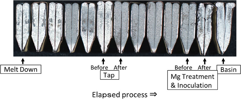
Fracture surfaces of wedge samples.
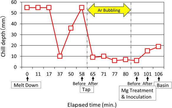
Changes of chill depth through elapsed time from melting to pouring.
The change of nitrogen quantities through the entire experimentation process is shown in Fig. 9. As expected, only NF in nitrogen morphologies showed good relationship at almost all of measuring points of chill depth, and that was seen even after molten treatment. When NF increased, chill depth had strong tendency to increase too. NT had no big change, and NI showed inversive change against NF. NF was decreased by the addition of C and Fe–75Si, and it was decreased effectively by Ar bubbling. However, NF was slightly increased when the bubbling time was longer. Molten treatment and pouring also made NF increase. The change of oxygen quantities through experimental process is shown in Fig. 10. None of OF, OI and OT showed any relationship to chill depth.

Changes of nitrogen content through elapsed time from melting to pouring.

Changes of oxygen content through elapsed time from melting to pouring.
The change of molten iron temperature throughout experimental process is shown in Fig. 11. TEC calculated from chemical composition is also plotted on it. When molten temperature was gone up by arc discharge at elapsed time between 37 and 58 minute, chill depth became deeper. However, temperature showed no relationship to chill depth directly. For example, chill depth increased although temperature descended after molten treatment. As the results, it shows that temperature was not main cause for chilling although higher temperature caused deeper chill in general theory. The important points on temperature for molten iron are to deoxidize by super heating and to avoid re-oxidization keeping over TEC. Temperature should not descend below TEC after super heating and before molten treatment.

Changes of molten temperature through elapsed from melting to pouring.
The change of chemical composition through experimental process is shown in Fig. 12. A large amount of C and Fe–75Si were added to adjust chemical composition roughly at elapsed time X, and then, chill depth decreased steeply. The same was true when C and Fe–75Si were added for the final adjustment chemical composition as base iron at elapsed time Y under Ar bubbling. However, Chill depth increased although Si increased by Mg spheroidizer and inoculant at elapsed time Z. When treated-molten iron was moved to basin, Mg decreased. The loss of Mg content must be made by re-oxidation forming Mg dross. On the contrarily, NF increased, and chill depth became deeper. The increasing of chilling tendency so called fading is usually seen as time advances after molten treatment in general foundry practice. The increasing of NF must be made by nitrification from atmosphere.

Changes of chemical composition through elapsed from melting to pouring.
The microstructure and mechanical properties of the cast-on test sample are shown in Fig. 13(a) and Table 5, respectively. Despite concerns about the formation of ledeburite cementite and/or inverse chill because of the tendency towards chilling in wedge samples as described above, the microstructure and mechanical properties of the cast-on sample were good in their results. Casting product had also no problem on it. This is attributed to the large size of the product casting and slow cooling rate utilized in this study. In later practical production, if chill depth is less than 20 mm there has been no chill problem for sand molded large castings. This value of chill depth is equivalent to NF content of about 10 ppm. Lower content is better to avoid chill formation. Figure 13(b) presents an example of the chill microstructure of the cast-on test sample in conventional practice which NF was not controlled.

Microstructures of cast-on samples.

If the same procedure is adopted into castings with faster cooling rate than this study, severer NF control will be necessary. If the control is possible, even permanent mold castings are free from chill in as cast condition.19,20)
According to “ISO 10702-1996, 4. a) Titrimetric method after distillation”, this analysis method cannot be used samples which contain silicon nitride (Si3N4). This is the reason because Si3N4 partly resolve in hydrochloric acid (HCl)21) and therefore, acid soluble and acid insoluble nitrides cannot be separated. Si3N4 is normally formed when samples are kept at around 500°C.21) No researcher has found and reported yet that it is formed in molten state. In this study, samples were directly taken from molten iron and soon after, they were quenched in water. In this condition, there was no doubt not to form Si3N4 in them. Therefore, above titrimetric method after distillation can be applicable for such samples.
4.2 Relationship between NF and chill depthThere was good relationship between NF and chill depth. However, the first sampling after tapping was not so. This was considered as the reason why the time lag for those samplings was about 60 seconds and the sampling point was under large transitional period of decreasing NF.
4.3 Formation of Fe3(CxNy)As described above, NF showed a strong correlation to the chill depth. It even has possibility to promote chill formation if cooling rate is fast as permanent mold casting. This correlation is considered necessary condition for the formation of ledeburite.
S. Nishi, et al. had reported that nitrogen was contained as solid solution in both eutectic and eutectoid cementite.22) K. Masumoto, et al.23) had estimated that the resolution of N in Fe3C was less than 1.00 mass% as the result of analyzing Fe–C–N system equilibrium phase diagram.24) As the results of consideration by standard free energy of nitride formation, N. Inoyama25) had concluded that dissolved nitrogen, which was analyzed as one of acid-soluble nitrogen morphologies, made eutectic cementite stable, and it delayed graphitization of malleable iron. A. Kagawa26) had reported that nitrogen was one of carbide stabilization elements as the results of investigation of partition coefficient in eutectic solidification of grey iron.
According to the atomic size, it is probable for N atoms to solute interstitially into Fe3C crystal structure because the diameter of the N atom (1.06 Å) is smaller than that of the C atom (1.42 Å).27)
The existence of iron carbonitride in the solid state has already been reported by D. Liedtke et al.28) However, there has been no report on Fe3(CN) in ledeburite cementite so far. NF is not stable in the liquid state because nitrogen (here NF) is a gas-state element. A part of the Fe–C system equilibrium phase diagram illustrating the possibility of Fe3(CxNy) formation is shown in Fig. 14. X and y mean the ratio of C vs. N if the total is 100%. If the solidification is slow enough, and NF value is rather high, NF might take the gas state as casting defect. In contrast, if solidification is fast enough, and NF value is rather high, NF has possibility to take Fe3(CxNy) form. If NF is controlled low enough by sufficient denitrification, chill formation can be prevented, and full graphite structure can be guaranteed in even permanent mold casting.19,20) There is no doubt that there is critical quantity of NF against cooling rate. This will be the next study theme. It is also interesting to survey the ratio of x and y in Fe3(CxNy) using X-ray diffraction.

Iron range of estimated Fe–C system equilibrium phase diagram with and without NF.
The formation of Fe3(CxNy) is also supported the possibility by the bonding properties of Fe and N from the viewpoint of the electronegativity.2,11,12,29) The difference in electronegativity of Fe and N is larger than that of Fe and C as described below.
| \begin{align*} \text{Difference between}\ &\text{Fe (1.8) and N (3.0)} = 1.2 \\ &\text{Fe (1.8) and C (2.5)} = 0.7 \end{align*} |
Mostly, nitrogen in atmosphere is considered as the source of NF. Although molecular N2 is known as an inert gas and is considered stable from other conditions, the gaseous state might be dissociated when molten iron is exposed at high temperature. For example, it has been known that nitrogen oxide (NOx) is generated by lightning30) or by heating of air over 1,000°C.31) These phenomena indicate the possibility of the generation of atomic N through reaction processes. These situations are resembling the condition of molten iron surface during electrical arc discharge, argon bubbling and pouring. Such atomic N generated might be absorbed into molten iron. Surface area of molten iron faced atmosphere should be narrow as possible. As the similar phenomena, nitrogen adsorption during steel welding and melting had been already reported by many researchers.32–34) N2 gas is used for stirring of molten steel instead of Ag gas in some cases as the reasons of cost performance.35) As a matter of course, molten steel naturally absorbs nitrogen in this case. However, the nitrogen absorption has been considered in the analytical results and the influence of product qualities.
4.5 DenitrificationSuperheating is mainly applied for deoxidation of base molten iron utilizing CO boiling. The reaction begins when temperature of molten iron exceeds TEC.
| \begin{equation} \text{SiO$_{2}$} + \text{2C} \Rightarrow \text{Si} + \text{2CO$\uparrow$} \end{equation} | (4) |
After superheating, temperature of molten iron can be lowered to TEC. During descending temperature, denitrification is expected by decreasing solubility of nitrogen in molten iron. TEC depends on the values of C and Si in base molten iron.
Although C and Si are added to minimize defects such as shrinkage and to guarantee the mechanical properties, they are also expected to minimize nitrogen adsorption36) and the risk of chill formation.37)
Besides C and Si, sulfur (S) is important to avoid nitrogen absorption. It should be value among the range of 0.006∼0.015 mass%.38) If S content is too low like less than 0.003 mass%, nitrogen absorption is aggressive. On the contrary if S content is too high like over 0.020 mass%, graphite nodularity cannot be secured. S content to get a good balance considering both the denitrification and the nodularity is around 0.012 mass% in base molten iron. Since basic slag is formed and a basic lining is used in the electric arc furnace, base molten iron is desulfurized during melting. Therefore, S (for example, Fe–48S) shall be added if needed to avoid nitrification and chill.
Ar bubbling is effective to denitrify but the apparatus with porous plug must be installed on the bottom of ladle. There is another type which inserts porous plug from the surface molten iron. However, the operation facility for plug going up and down is needed. Another problem is that the surface area of plug refractory, which is inserted into molten iron, is larger. Those means that the cost performance is worse, and the place for installed apparatus is needed.
Vacuum melting must be the most effective method for degassing including denitrification, but this method is not suitable for Mg treated molten iron since Mg exists gas state and reduces the content by vacuum. Furthermore, it does not have reality for foundry practice because it does not fit mass production and cost performance for iron castings.
4.6 Mg treatmentT. Choh39) had reported that the rate and the quantity of nitrogen adsorption became higher and more respectively when S content in molten iron had quite less. Unfortunately, the nitrogen morphology was not indicated. The influence of oxygen had been reported to take similar phenomenon as well. T. Choh had also suggested that the higher temperature promoted the stronger tendency of nitrogen adsorption. The temperature of Mg treatment should be lower as possible but should avoid much below TEC. As described in 4.5, S content must set higher value which does not disturb graphite nodularity. Mg treatment introduces not only graphite spheroidization but also bring desulfurization and deoxidation. These might make the chance of nitrogen adsorption again.
Mg vaporizes and boils at over 1,100°C. When the temperature is much higher than this, and/or when spheroidizer agent contain high amount of Mg, the vapor pressure become higher and the molten surface causes severe waves as seen on boiling water. This makes surface area of molten iron larger, and the chance of nitrogen adsorption may increase.
It is generally considered that chilling tendency decrease when large amount of Si increased by molten treatment. However, chilling tendency increased with increasing NF as shown in Fig. 8 and 9. Spheroidizing agents with lower Mg content as possible should be selected to achieve gentle Mg vaporization. Air-off by shrouding molten surface during Mg treatment might be also effective to avoid nitrogen adsorption. This has been trying for permanent mold casting and the results will be published in near future.40)
As described above, it is considered that Mg does not make chilling tendency increase itself, but nitrogen adsorption makes it. Mg atom is diameter of 3.20 Å, and it is much larger than that of Fe atom (2.48 Å). It is almost impossible that Mg atom replaces Fe atom in Fe3C crystal structure.
4.7 InoculationInoculation might be considered to impart two effects.41) The illustration is shown in Fig. 15. One is the offset of NF and avoid the risk of chill formation. In fact, powerful inoculants in melting practice contain elements such as aluminum (Al), calcium (Ca), strontium (Sr), zirconium (Zr), etc. which show strong affinity for NF in all. Alloy makers empirically determined the elemental compositions with almost no theory, based on trial and error. Another effect is to introduce micro-concentration spots of Si into the molten iron. This mainly causes the nodule number to increase. These inoculation effects are gradually lost with time. The phenomenon is called fading. At this moment, molten iron has almost no offset ability of NF anymore. Fading leads to re-nitrogen adsorption. And micro-concentration spots of Si are homogenized, and the number of graphite nucleation sites decreases. Therefore, inoculation should be conducted at the final stage as possible before solidification starts.

Potential and expected effects by inoculation.
Pouring must be conducted as fast as possible after inoculation,42) and the stream must be laminar flow to reduce the surface area of Mg treated molten iron.43) As the results, it can make nitrogen adsorption minimize. Discussion about molds, the lower the amount of combustion gas, including nitrogen gas system, is better. The ignition loss in the sand mold must be low enough. Molten flow in the sand mold is desired to be as calm and fast as possible.
4.9 Stability of graphite system solidificationAs described all above, the cause of cementite system solidification was obvious to be an involvement of NF. If the mechanism, which NF involves cementite crystal structure, is clearer, complicated inoculation mechanism will be understandable. As the results, foundrymen will become easier to get graphite system solidification in any cases like the field of thin wall sand mold casting, permanent mold casting, die casting etc.
4.10 Difference from conventional theoryAuthors propose “The Free Nitrogen Theory” as the mechanism of chill formation in spheroidal graphite cast iron castings. The theory would be also applicable for other types of grey iron castings, in common. This theory treats only NF in nitrogen morphology and is different from that proposed by Y. Lee1,3) and N. Inoyama.2) They had stated NS, which included NF, AlN and Mg3N2 (Fig. 1). Their theory could not reach the technical development for the foundry site. On the other hand, the theory proposed by authors can be applied already in actual foundry field like this study. The realization of chill-free permanent mold casting of thin wall spheroidal graphite iron castings, which is not succeeded almost no party in foundry, have been already in author’s hands.19,20) Thus, there is big difference between two theories on the production of castings. Theory should be simple as possible for metallurgist and foundry engineer, and it should be useful to MONODUKURI (manufacturing) for foundrymen too.
Through EAF melting and the later molten treatment process, the following points were found on chilling in spheroidal graphite iron castings: