Abstract
Metallic silicon powder has been widely used for the production of various industrial materials and parts such as refractory ceramics, solar cells, military parts and so on. Herein, we attempted to prepare pure silicon powder from SiO2 by a magnesium thermal reduction process. A mixed-phase, Mg2Si + MgO, was obtained by the reduction of SiO2 powder by magnesium gas at 1223 K for 20 h. To extract pure silicon powder, Mg was separated by evaporation under vacuum through Mg2Si decomposition above 1073 K, leading to the formation of Si + MgO, and the MgO by-product was eliminated by dissolution in an aqueous hydrochloric acid solution. X-ray diffraction analysis confirmed the formation of pure Si powder and particle size shown in microstructure and oxygen content were analyzed to be 1∼5 µm and 1.5∼6 wt.%, respectively.
1. Introduction
Fine silicon powder has been used usually as a raw material for the production of high value-added high melting point powders such as SiC and Si3N4, medical treatment materials, catalysts, electromagnetic components for various devices, and solar cells.1–7) In particular, Si3N4 powder has excellent hardness, creep strength, oxidation resistance, and thermochemical stability. Thus, it has been extensively used as a raw material for high-performance tools, ball bearings, turbocharger parts, and other products.8–10)
Many processes have been developed for manufacturing Si3N4 powder, including a direct nitration process of silicon powder, a silicon diimide process, a carbothermal reduction and nitration process using SiO2 powder, a gas phase reaction process, plasma process, and so on.11–15) Among them, the direct nitration and diimide methods are known to be commercialized in industries.16,17) Direct nitration is based on the direct reaction between metallic Si powder and nitrogen gas at an elevated temperature and the diimide methods, the decomposition of silicon chloride as start material, and reaction with ammonia gas for nitration. On the other hand, many researchers have suggested nitration of Si is a more simple and easy process and therefore concentrated on the development of the Si powder with high purity.
Mainly two processes have been researched to produce the fine metallic silicon powder 1) ball milling of Si scrap18) and 2) the magnesium reduction from SiO2.19–23) The ball milling is known to be a simple process however, it has often contamination problems as for bulk Si to be powdered finely.
The magnesium reduction process was also intensively researched because the driving force for reduction is enough high and the magnesium is vaporized easily even below 1273 K. The reactions of magnesium reduction can be described as below eqs. (1) and (2), which let us know that not only Si but also Mg2Si can be formed with different amount of reducer.24–36)
| \begin{align}
&\text{SiO$_{2}$} + \text{2Mg} \to \text{Si} + \text{2MgO} \\
&\quad \Delta\text{G}_{\text{1023K${\sim}$1223K}} = -320{\sim}{-}270\,\text{kJ/mol}
\end{align}
| (1) |
| \begin{align}
&\text{SiO$_{2}$} + \text{4Mg} \to \text{Mg$_{2}$Si} + \text{2MgO}\\
& \quad \Delta\text{G}_{\text{1023K${\sim}$1223K}} = -454{\sim}{-}360\,\text{kJ/mol}
\end{align}
| (2) |
It was reported that both gaseous and solid phase of the magnesium has been used as the reductant, however, the gaseous reaction more actively performed because of cost-up according to use of solid magnesium powder.25–29,32)
It should be noted that a Mg2SiO4 has been formed as the intermediated phase in almost all studies for Mg-reduction of SiO2 and resulted in decreasing the Si purity. We have considered there that the reason for the formation of Mg2SiO4 could be explained by 1) use the air atmosphere, 2) low partial pressure of Mg gas and 3) reaction of unreduced SiO2 and MgO, which may be resulted from employing Si as target material.24,26,35,37)
Therefore, in this study, the several routes to avoid the formation of Mg2SiO4 and maximize the Si purity while the reduction reaction were suggested 1) Ar gas atmosphere was used, 2) Mg was charged excessively to sustain the high partial pressure of Mg gas, 3) Not Si but Mg2Si was selected as the target material.
According to Ma’s report, Mg2Si could be removed by a simple acidic cleaning treatment33) however, it may cause not only a low recovery rate of Si metal powder but also the explosive reaction behavior of Mg2Si and HCl. Therefore we proposed the vacuum decomposition of Mg2Si. Mg2Si is thermodynamically stable so does not decomposed in all temperature ranges at 1.01 × 10⁵ Pa. However, we believed it can be decomposed in a vacuum condition and knew there are no studies on recovering Si powder from Mg2Si by vacuum decomposition.
This study aimed to produce Si powder via vacuum decomposition of Mg2Si produced by the Mg reduction process using SiO2. Also, considering that the particle size and oxygen content of commercial Si3N4 powder are known to be about 1 µm and 1∼2 wt.%, respectively, we hope to check the possibility of our produced Si to be applied for the production of Si3N4 powder.
2. Materials and Methods
For the magnesium reduction, we used SiO2 powder (99.99%) and pure magnesium (99.9%) purchased from US Research Nanomaterials, Inc. (Houston, TX USA) as raw materials.
Considering the molar masses in reaction (2), the reaction mass ratio of SiO2 to Mg is approximately 60:96. In this study, 20 g of SiO2 raw material powder was selected. Although the theoretical amount of Mg required to reduce this amount of SiO2 is 32 g, 200 g of Mg was used for sufficient reduction reaction. The prepared SiO2 powder were placed with about 5 mm thickness on graphite trays (diameter 100 mm) and irregularly shaped Mg fragments of about 10 mm in size separately, finally covered with a graphite cap. The inner wall of the graphite tray containing SiO2 was painted and dried by 10%-MgO ethanol solution to prevent the reaction between the reduced Si and carbon and then placed into a stainless-steel chamber, as depicted in Fig. 1. After reducing the pressure in the chamber to 7 Pa with a mechanical oil vacuum pump, argon gas of 99.999% purity (PS Chem Co. LTD, KOREA) was injected to reach atmospheric pressure, and the chamber was evacuated again. After repeating this process several times, the chamber was finally filled with argon gas at 1.1 × 10⁵ Pa and then heated by 15 K/min to 1023 K, 1123 K and 1223 K, respectively. The reduction reaction was carried out for 20 h at those temperatures and then the chamber was cooled under the same atmosphere.

During the reduction reaction, the partial pressure of magnesium gas inside the tray should be constant. Here it should be noted that not only the magnesium gas inside the graphite tray is involved in the reaction, but also a certain amount can be emitted and consumed outside of the tray. In other words, when the charged amount of magnesium in the tray is small, the internal partial pressure of the magnesium gas can be decreased and by it, the consistent reduction behavior can become difficult for the whole reduction period. Therefore, it was tried to measure the total consumption amount of magnesium by emission between 1023–1223 K for 20 h and the result was about ∼90 g. Therefore, we decided to charge a sufficient amount of magnesium, 200 g.
The product after the reduction reaction was a Mg2Si + MgO mixture and placed on another tray made of stainless steel (SUS 304) for the process of vacuum decomposition. It is due to eliminating the carbon contamination into Si decomposed from Mg2Si in vacuum condition. The inner wall of the SUS-tray was also painted by MgO and dried just in case. The vacuum heat treatments were performed at 7 Pa at 973 K, 1073 K or 1173 K, for 0.5, 1, 5, and 10 h, respectively.
The reaction product after finishing decomposition was Si + MgO mixture. It was stirred and rinsed three times for 20 min. in 10% hydrochloric acid solution to remove MgO and five times for 10 min. in distilled water to further remove residual MgCl2 remaining after acid leaching,26,28,33) thereby finally obtained the Si metal powder.
The microstructures and phases of the obtained Si metal powder were evaluated using an oxygen-nitrogen hydrogen determinator (ELTRA ONH-P), Inductively Coupled Plasma Mass Spectrometer (ICP, Varian 820), scanning electron microscopy (SEM, TESCAN MIRA3-LM) and X-ray diffraction analysis, (40 kV 250 mA radiation, Cu Ka), (Rigaku International Corporation D/Max-2500), respectively.
3. Results and Discussions
Figure 2(a) shows an SEM image of the SiO2 powder used as the initial raw material. The image shows mostly irregularly shaped particles. The particle size was ∼4 µm, and the SiO2 single phase was confirmed by X-ray diffraction analysis.
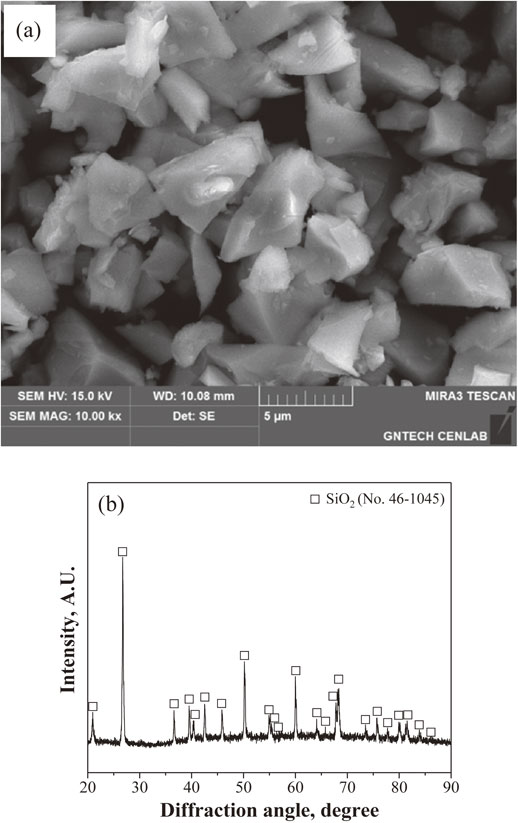
Figure 3 shows a schematic of the magnesium gas reduction and vacuum decomposition proposed in this study. Concerning the reduction reaction, it can be known that it has sufficient driving forces as shown in eqs. (1) and (2). The reduction of SiO2 particles starts from the particle surfaces by reaction with magnesium gas, forming a magnesium oxide film on the particle surfaces and Mg2Si inside the particles. The Mg2Si obtained after completion of the reduction was decomposed into magnesium gas and silicon from vacuum decomposition. The evaporated magnesium gas was also condensed at the cooling zone at the upper distribution part of the reactor, as shown in Fig. 1, thereby recovering a composite powder of Si + MgO. Here we recognized that the vaporized and condensed magnesium in the cooling zone can be recycled for the next reduction because its purity was very high. Thereafter, the recovered composite powder was stirred in a hydrochloric acid aqueous solution to remove the residual MgO thus to obtain the final Si powder.

Figure 4 shows X-ray diffraction profiles for the powders produced at various reduction temperatures. At a relatively low reduction temperature, 1023 K, a significant amount of SiO2 phase was detected, indicating incomplete reduction. In the case of 1123 K, no SiO2 phase was observed however small peaks corresponding to Si were shown, which let us know that the reduction was enough formed but full production of Mg2Si was not accomplished. Meanwhile, at 1223 K, only the Mg2Si and MgO phases were detected as designed. Therefore, we considered 1223 K to be a sufficient reduction temperature.

It was required to study the phases to be formed possibly during reduction. For it, the Mg–Si–O ternary phase diagram (Thermo-Calc, Royal Institute of Technology (KTH), Stockholm, Sweden) was found (Fig. 5). It was shown the equilibrium phases of Mg2SiO4 and MgSiO3. When excess Mg and MgO coexist, Mg2SiO4 does not exist according to the phase diagram, and Mg2Si becomes stable. And it can be reached to the three-phase equilibria, Mg–Mg2Si–MgO through the three-phase equilibria, MgO–Mg2Si–Si during reduction because the partial pressure of Mg was enough high and the oxygen potential, low.

Also, because the Mg reduction temperature, 1223 K which we employed is slightly higher than the eutectic point, 1218.6 K, a small amount of eutectic liquids, MgO+Mg2Si+Mg2Si-rich eutectic liquid or MgO+Mg2Si+Si-rich can be mixed with Mg2Si. We believed that such eutectic liquid can be also decomposed thus transformed to Si phase even if this Si possibly has different morphology with Si coming from Mg2Si. Anyway, such an effect can decrease the homogeneity of the final product, Si powder hence it has been carried out newly at a temperature a little lower than the eutectic point.
Figure 6 shows the free energy changes for the decomposition behaviors of Mg2Si at various temperatures and pressures. Here, it can be known that Mg2Si is stable in all temperature regions at 1.01 × 10⁵ Pa but can be decomposed above 900 K and at 7 Pa of vacuum condition. After that, the decomposed magnesium would exist as a volatilized liquid phase at such a condition. Therefore, only the Si component can remain because its vapor pressure Si is extremely low, about 10−8 Pa. It was found experimentally that the vacuum degree inside the tray was slightly increased by vaporized magnesium and recovered quickly to the initial vacuum degree in a middle stage of decomposition.

Figure 7 shows X-ray diffraction profiles for the powder vacuum decomposed for 5 h at 973 K, 1073 K, and 1173 K with Mg2Si + MgO mixture reduced at 1223 K. For the samples prepared at 973 K, which is slightly higher than 900 K of theoretical value shown in Fig. 6, almost no decomposition was achieved. In contrast, at 1073 K or higher, two phases—Si (decomposed from Mg2Si) and MgO (the by-product of reduction)—were formed, confirming that the vacuum decomposition had finished properly.

Although no Mg2Si phase is seen in the X-ray data, a small amount of Mg2Si may still remain. The main problems for the presence of a small amount of Mg2Si are not only it is an impurity in the final Si powder but also can make it difficult for the next acid leaching process. That is why explosive flaming can occur when even a trace amount of Mg2Si meets hydrochloric acid solution.37) Therefore, before acid leaching, it was tried the contacting test with 0.2 g of vacuum-decomposed powder and 10% hydrochloric acid solution to identify the presence/absence of Mg2Si and that result is in Table 1. The results showed that if the temperature of vacuum decomposition treatment was low or the treatment time was short, then even a small amount of Mg2Si remained.
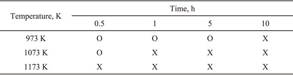
Table 1 Test results showing flame formation (O) or no flame formation (X) when 10% hydrochloric acid solution reacts with the powder obtained after vacuum decomposition under various conditions.
After the above flaming test, we could know to confirm the absence of Mg2Si, then follow safely the acid leaching. Figure 8 shows a representative X-ray diffraction profile for Si metal powder obtained by removing the MgO component using 10% hydrochloric acid solution from the Si + MgO mixture vacuum-decomposed for 5 h at 1073 K. The result shows that the Si phase was well-formed, confirming that MgO was properly removed. The magnesium content as an impurity was analyzed to 150 ppm by inductively coupled plasma analysis (ICP). However, considering it has been known that the several weight percent of MgO is mixed as an additive into Si3N4 for sintering process,38) we suggested somewhat MgO impurity can be allowed.

Figure 9 presents SEM images of Si metal powder after vacuum-decomposition at 1073 K and 1173 K, as representative cases and acid leaching. The particle sizes were in the range of 1∼5 µm and a slightly coarse Si metal powder was shown at a relatively high vacuum decomposition temperature of 1173 K. Meanwhile, the produced Si particles were finer than the raw SiO2 particles shown in Fig. 2, a), likely because the Si particles that had separated and formed from Mg2Si were not effectively grown.

On the other hand, oxygen analysis should be performed on the produced Si powder. In general, oxygen in metal powder can exist as dissolved oxygen inside the metal particles and in the passivation film formed on the particle surface.39) However, the oxygen solubility of the Si is 0.001 wt.% It is very low.40) Therefore, in this study, oxygen is expected to primarily be present in the passivation film. The oxygen analysis results in Fig. 10 show that as the vacuum decomposition time increased from 0.5 h to 10 h, the oxygen concentration decreased, from 8.2 wt.% to 3.4 wt.% at 1073 K and from 6.1 wt.% to 1.5 wt.% at 1173 K. Overall, the decrease in the oxygen concentration with the increase in the vacuum treatment temperature and time can be explained by the decrease of specific surface area due to the particle coarsening effect. This study found that Si powder with about 1.5 wt.% of minimal oxygen content could be produced by the proposed process. However, overall oxygen concentrations were in Fig. 10 significantly high, which was probably due to an effect of the presence of extremely fine powder, in particular, such nano-sized Si powders may react with water to form an amorphous phase.41) The oxidation mechanism, in particular during acid leaching, of Si powder decomposed from Mg2Si is being studied.

4. Conclusion
Using SiO2 with an average particle size of ∼4 µm as the initial raw material, pure Si metal powder was successfully produced through a Mg gas reduction reaction, following vacuum decomposition of Mg2Si and acid leaching. X-ray diffraction analysis of the powder obtained after performing the magnesium gas reduction reaction at various temperatures confirmed that 1223 K was the ideal reduction reaction temperature and vacuum decomposition was well accomplished above 1073 K. Finally, the oxygen concentration of the Si powder produced by acid cleaning treatment tended to decrease as the heat treatment temperature and time increased. The size of produced Si powder was 1∼5 µm and the minimal oxygen concentration was obtained to be 1.5 wt.% by vacuum decompositions for 10 h at 1173 K.
Acknowledgments
This work was supported by the Korea Institute of Materials Science (KIMS) under the project PNK 7450. The authors wish to thank Dong-Won Lee from the Titanium Department at KIMS. There are no conflicts of interest. This work was supported by the Korea Institute of Materials Science of Korea (project number PNK 7450).
REFERENCES
- 1) L.J. Chen: J. Mater. Chem. 17 (2007) 4639–4643.
- 2) A. Reindl, C. Cimpean, W. Bauer, R. Comanici, A. Ebbers, W. Peukert and C. Kryschi: Colloids Surf. A Physicochem. Eng. Asp. 301 (2007) 382–387.
- 3) Z.F. Li and E. Ruckenstein: Nano Lett. 4 (2004) 1463–1467.
- 4) A. Reindl, A. Voronov, P.K. Gorle, M. Rauscher, A. Roosen and W. Peukert: Colloids Surf. A Physicochem. Eng. Asp. 320 (2008) 183–188.
- 5) M.C. Beard, K.P. Knutsen, P. Yu, J.M. Luther, Q. Song, W.K. Metzger, R.J. Ellingson and A.J. Nozik: Nano Lett. 7 (2007) 2506–2512.
- 6) H. Dalaker and M. Tangstad: Mater. Trans. 50 (2009) 2541–2544.
- 7) H. Morito, H. Yamane, T. Yamada, S. Yin and T. Sato: Mater. Trans. 49 (2008) 1929–1933.
- 8) D. Scott, J. Blackwell and P.J. McCullagh: Wear 17 (1971) 73–82.
- 9) E. Kannatey-Asibu, Jr.: J. Manuf. Syst. 9 (1990) 159–168.
- 10) H.Z. Miao, L.H. Qi and G. Cui: Key Eng. Mater. 114 (1995) 135–172.
- 11) H. Arik, S. Saritas and M. Gündüz: J. Mater. Sci. 34 (1999) 835–842.
- 12) T. Licko, V. Figusch and J. Puchyova: J. Eur. Ceram. Soc. 9 (1992) 219–230.
- 13) H. Arik: J. Eur. Ceram. Soc. 23 (2003) 2005–2014.
- 14) T. Yang, A.M. Thomas, B.B. Dangi, R.I. Kaiser, A.M. Mebel and T.J. Millar: Nat. Commun. 9 (2018) 774.
- 15) Z. Li, J. Huang, Z. Zhang, F. Zhao and Y. Wu: Mater. Sci. Eng. B 229 (2018) 6–12.
- 16) V. Pavarajarn and S. Kimura: Ind. Eng. Chem. Res. 42 (2003) 2434–2440.
- 17) A. Ortega, M.D. Alcalá and C. Real: J. Mater. Process. Technol. 195 (2008) 224–231.
- 18) B.E. Nilssen and R.A. Kleiv: Silicon 12 (2020) 2413–2423.
- 19) W. Luo, X. Wang, C. Meyers, N. Wannenmacher, W. Sirisaksoontorn, M.M. Lerner and X. Ji: Sci. Rep. 3 (2013) 2222.
- 20) K. Chen, Z. Bao, J. Shen, G. Wu, B. Zhou and K.H. Sandhage: J. Mater. Chem. 22 (2012) 16196–16200.
- 21) Y. Iwadate, K. Ohgane and T. Ohkubo: Electrochemistry 86 (2018) 198–201.
- 22) W. Chen, Z. Fan, A. Dhanabalan, C. Chen and C. Wang: J. Electrochem. Soc. 158 (2011) A1055–A1059.
- 23) E.K. Richman, C.B. Kang, T. Brezesinski and S.H. Tolbert: Nano Lett. 8 (2008) 3075–3079.
- 24) H.D. Banerjee, S. Sen and H.N. Acharya: Mater. Sci. Eng. 52 (1982) 173–179.
- 25) K.H. Sandhage, M.B. Dickerson, P.M. Huseman, M.A. Caranna, J.D. Clifton, T.A. Bull, T.J. Heibel, W.R. Overton and M.E.A. Schoenwaelder: Adv. Mater. 14 (2002) 429–433.
- 26) Zh. Yermekova, Z. Mansurov and A.S. Mukasyan: Int. J. Self-Propag. High-Temp. Synth. 19 (2010) 94–101.
- 27) Y. Zhang and J. Huang: J. Mater. Chem. 21 (2011) 7161–7165.
- 28) D.P. Wong, H.-T. Lien, Y.-T. Chen, K.-H. Chen and L.-C. Chen: Green Chem. 14 (2012) 896–900.
- 29) W. Luo, X. Wang, C. Meyers, N. Wannenmacher, W. Sirisaksoontorn, M.M. Lerner and X. Ji: Sci. Rep. 3 (2013) 2222.
- 30) I.A. Ødegard, J. Romann, A. Fossdal, A. Røyset and G. Tranell: J. Mater. Chem. A 2 (2014) 16410–16415.
- 31) H.-C. Tao, L.-Z. Fan and X. Qu: Electrochim. Acta 71 (2012) 194–200.
- 32) K.H. Kim, D.J. Lee, K.M. Cho, S.J. Kim, J.-K. Park and H.-T. Jung: Sci. Rep. 5 (2015) 9014.
- 33) B. Ma, Z. Huang, L. Mei, M. Fang, Y. Liu and X. Wu: Surf. Eng. 32 (2016) 761–765.
- 34) Y. Tsuboi, S. Ura, K. Takahiro, T. Henmi, A. Okada, T. Wakasugi and K. Kadono: J. Asian Ceram. Soc. 5 (2017) 341–349.
- 35) J. Entwistle, A. Rennie and S. Patwardhan: J. Mater. Chem. A 6 (2018) 18344–18356.
- 36) T. Henmi, T. Shiono, K. Matsubara, T. Kiyomura, H. Kurata, T. Wakasugi, A. Okada and K. Kadono: Int. J. Ceram. Eng. Sci. 2 (2020) 66–75.
- 37) M. Barati, S. Sarder, A. McLean and R. Roy: J. Non-Cryst. Solids 357 (2011) 18–23.
- 38) V. Demir and D.P. Thompson: J. Mater. Sci. 40 (2005) 1763–1765.
- 39) W. Ji, W. Zhao, H.M. Fahad, J. Bullock, T. Allen, D.-H. Lien, S.D. Wolf and A. Javey: ACS Nano 13 (2019) 3723–3729.
- 40) H. Okamoto: J. Phase Equilib. Diffus. 28 (2007) 309–310.
- 41) G.B. Alexander, W.M. Heston and R.K. ller: J. Phys. Chem. 58 (1954) 453–455.

