Abstract
Electromagnetic pulse welding is a new promising method for solid-state joining of dissimilar materials. However, little understanding of the dynamic phenomena that leads interface morphology and intermetallic compounds to change. Initially, using Ansys Maxwell proved that the eddy current heat had a softening effect on aluminum alloy, and could press into the stainless steel in the semi-melted state. IMCs layer transferred from the unwelded zone (FeAl) to the flat welded zone (Fe2Al5+FeAl2+FeAl) to the wave interface (α-Al+FeAl3), the state of jet determined interface performance. Then, these insights were verified by SPH simulation, dispersed jet made soft aluminum alloy to produce the wave interface, a beam jet that aluminum particles were wrapped by steel particles produced the flat interface. Combination shear tests, the welded interface with high strength was characterized by large waveform, molten metal and a small amount of steel particles, formed Al-rich FeAl3. The welded seam with low strength shown brittle fracture characteristic of spherical intermetallic compounds iron-rich FeAl formed by retention jets. Therefore, the dominant mechanism of interface formation is that the compression and impact effect of jet accompanied by a softening effect of eddy current heat on aluminum alloy.

1. Introduction
Lightweight and corrosion-resistant materials (e.g., aluminum and aluminum alloys) have become the substitutes for traditional steel, and gradually been applied in the fields of aerospace, shipbuilding, and railways. However, due to the large difference in thermophysical properties between aluminum and steel, the brazing filler metal makes the welded joint more brittle;1) for laser welding, relatively large heat input cause uneven composition of the weld seam, which is very easy to generate large internal stress;2) uneven heat-machine coupling in friction welding.3) Therefore, it is particularly necessary to select a welding method suitable for aluminum and steel.
Electromagnetic pulse welding is a new technology that uses electromagnetic force to make two workpieces impact at high velocity to achieve welding.4) At present, the researches on electromagnetic pulse welding of dissimilar metals have obtained identifiable results, and a consensus has been reached that the laws of influence of static parameters on the formation and performance of welded joint, the welded area increased when the discharge energy rose,5) the optimum standoff distance for two plain carbon steel plates.6,7) However, the dissimilar materials lead to the generation of brittle intermetallic compounds was harmful to the service life of welded joint.8) Besides changing static parameters on improving strength had inconspicuous effects, the scholars tried to add the magnetic collector,9) used double coils on the plate,10) coated metal before welding,11) and established the welding window.12) But a dynamic welding process is completed instantly to cause unstable property of welded joint,13) numerical simulation was done to gain the plastic deformation behavior of materials,14,15) simulated characteristics of interface wave,16) jet state generated by metal collision.17) However, previous studies cannot fully explain the joint process of the EMP welding interface by means of simulation alone, the influence of particle flow on the formation of intermetallic compounds should to be researched in depth. Therefore, there were three aspects had to be addresses, the first, SEM-EDS and XRD were adopted to evaluate the interface morphology and possible phase in the transition zone. The second, the distribution of magnetic field and temperature field by ANSYS software presented material characteristic in impacting process, combined with Gibbs free energy of Al–Fe and SPH simulation developed the relationship between metal jet and interface morphology. Finally, according to shear tests gained the fracture morphology under different jets, which can provide the theoretical guidance for controlling interface performance of welded joint.
2. Experimental Materials and Methods
2.1 Welding method and material preparation
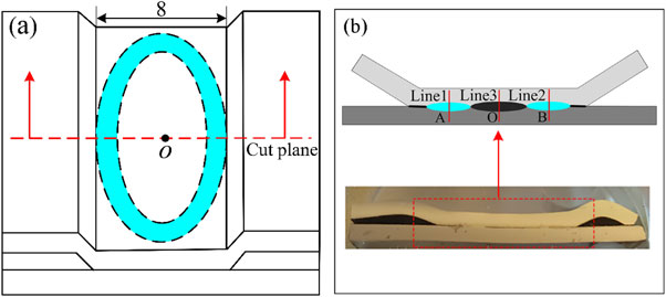
The 75 KJ Pulsar electromagnetic pulse welding equipment was used in this study with a total capacitance of 240 µF, a maximum charging voltage of 25 KV, and a maximum current of 900 KA. The welding device as shown in Fig. 1(a) and Fig. 1(b), the position to be welded was placed above the center beam of E-type coil, and the target plate was placed on the flyer plate in an overlapping form, and the overlapping length and overlapping gap were restrained by the cushion block. According to the Lorentz Force theory, when the capacitor discharges, the center beam of the coil produces an alternating magnetic field through the pulse current, and the flyer plate generates a strong magnetic induction current. The magnetic field generated by the induced current interacts with the magnetic field of coil to form repulsive force, which makes the flyer plate move upward instantly at a high velocity to impact the target plate, and finish welding.
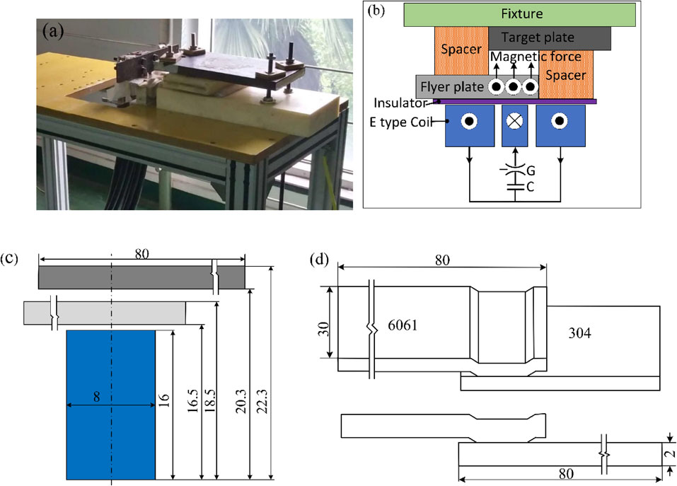
The test flyer plate was 6061 aluminum alloy, the target plate was 304 stainless steel, and the chemical compositions are shown in Table 1 and Table 2. The geometry dimensions were both 80 × 30 × 2 mm3, the overlapping length was 20 mm, the gap was 1.8 mm, as shown in Fig. 1(c), and the dimension of test sample is illustrated in Fig. 1(d). The force of friction is generated during the impact process, and friction heat provide energy for metallurgical bonding. Before welding, 600 # sandpaper was used to polish the part to be welded of plate in a suitable roughness, and remove the rust, and scrub with acetone to ensure that the surface was clean without oil stain.

Table 1 Chemical composition of 6061 aluminum alloy.
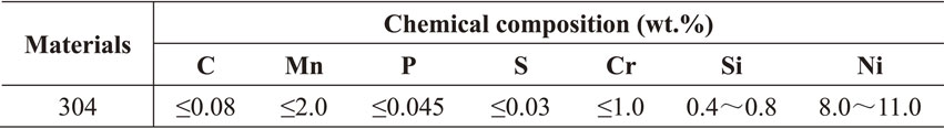
Table 2 Chemical composition of 304 stainless steel.
After welding, the observation of microscopic morphology at interface was taken along the direction parallel to electromagnetic pulse welding direction and perpendicular to the surface of the flyer plate as shown in Fig. 2(a). The welded joint was successively subject to wire cutting, grinding, inlaying, polishing, ultrasonic cleaning and corrosion. Zeiss ΣIGMA HD scanning electron microscope (SEM), energy disperse spectroscopy (EDS) and Shimadzu-XRD-700S were used to observe the microscopic characteristics of interface. HVS-1000Z automatic turret digital micro-hardness tester was used to measure the Vickers hardness at interface (along the Line 1, Line 2 and the Line 3) as shown in Fig. 2(b), the test conditions were: load 300 N, loading time 20 s.
2.2.2 Shear strength tests of welded joint
A 60T electronic universal testing machine was used to perform shear test on the welded joints, the dimension of test sample was based on the requirements of GB/T26957-2011 and AWS_D17-3-2010, the overlapping part was in the middle of the sample, two doubler plates with the same material and thickness as the base metal were used at the clamping part of the weldment for compensation, so as to weaken the unidirectional force which may produce a larger torque on the weld, and the welded joint would only be subject to pure shear stress after being loaded, as shown in the Fig. 3. The shear tests were performed on the samples with a frequency of 13 KHz and a discharge voltage of 15 KV and 12 KV respectively at the test load rate of 5 mm/min.
2.3 Simulation method
ANSYS Maxwell 19.0 was used to simulate the transient electromagnetic field, and the model parameters were consistent with the actual welding parameters. The discharge current was added to the coil as the excitation load, as shown in the following formula:
| \begin{equation}
I(\mathrm{t}) = I_{m}e^{-\beta t}\sin 2\pi ft
\end{equation}
| (1) |
The current of welding process was collected through the oscilloscope, and the Davenant correction was carried out. The maximum current was 350 KA, the attenuation coefficient was 4265, frequency was 17 KHz.
The smoothed particle hydrodynamics (SPH) method and the Johnson-Cook material constitutive model were used to perform simulation of the instantaneous jet morphology of the interface, according to the theoretical calculation of material and the maximum impact angle of 18 degrees at the end of welding, the minimum initial impact velocity required for welding was deduced to be 236.5 m/s, and the velocity components along the direction of vertical interface and welding direction were converted for SPH simulation. The particle diameter was 1 µm. The Johnson-Cook material model could accurately characterize the mechanical properties of materials under large deformation at high strain rate by reported,18) the equation of material as follows:
| \begin{equation}
\sigma = (A + B\varepsilon^{n})\left(1 + \mathrm{C}\ln\frac{\dot{\varepsilon}}{\dot{\varepsilon}_{0}}\right)\left(1 - \left[\frac{T - T_{r}}{T_{\textit{melt}} - T_{r}}\right]^{m}\right)
\end{equation}
| (2) |
Where A, B, C, m and n are the parameters of flyer plate, A, B and n denote strain hardening coefficients, C denote strain rate hardening coefficient, and m denote thermal softening coefficient; σ is the equivalent plastic stress, MPa; ε is the equivalent plastic strain, s−1; $\dot{\varepsilon }$ is the plastic strain rate, s−1; $\dot{\varepsilon }_{0} $ is the reference plastic strain rate, s−1; Tr is the reference temperature, °C; T melt is the melting temperature of material, °C; The Johnson-Cook material model as shown in Table 3.

Table 3 Parameters of Johnson-Cook material model.
3. Results and Discussion
3.1 Theoretical formulation of impact velocity of flyer plate
In order to weld two metal plates in high velocity impacting process, a pressure is required to remove oxides and form jet, which can be estimated by follows:19)
| \begin{equation}
P = 5 \times \textit{Hugomiot Elastic Limit}\ (\mathit{HEL})
\end{equation}
| (3) |
Where HEL is given as follows:
| \begin{equation}
\mathit{HEL} = \frac{1}{2}\left(\frac{K}{G} + \frac{4}{3}\right)Y_{0}
\end{equation}
| (4) |
Where K is the bulk modulus, G is shear modulus, Y0 is the tensile yield stress. The material properties are illustrated in Table 4.
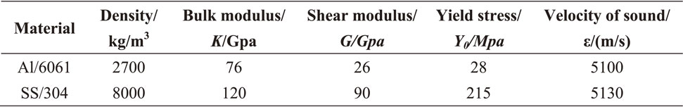
Table 4 Material properties in calculated impact velocity equivalent.
The calculated impact pressure (P) was 2.979 × 10⁸ Pa, and then the impact velocity in welding process can be deduced from follow equivalent:
| \begin{equation}
V = \frac{2P}{Z_{eq}\cos\alpha}
\end{equation}
| (5) |
| \begin{equation}
Z_{eq} = \cfrac{2}{\cfrac{1}{Z_{1}} + \cfrac{1}{Z_{2}}}
\end{equation}
| (6) |
Where V is the impact velocity, α is the impact angle, Zeq is the equivalent acoustic impedance of impact plates, 2.6515 × 10⁶, Z1 = ρ1ε1 is the flyer plate acoustic impedance, 1.377 × 10⁷; Z2 = ρ2ε2 is the target plate acoustic impedance, 4.104 × 10⁷; ε1, ε2 are the velocities of sound in the flyer plate and target plate materials respectively, ρ1, ρ2 are the material densities of the two materials.
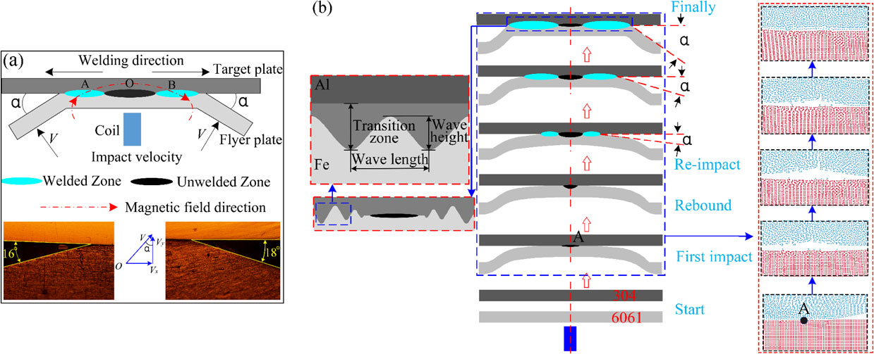
Figure 4 shows the variations of impact angle to welded seam. The calculated impact velocity was 236.5 m/s under impact angle with 18 degrees, and the other one was 16 degrees. The impact velocity produces two velocity components in the direction of pressed stainless steel and welding respectively. With angle increasing, the velocity component Vx increases, the welding length per unit time increases, namely the wavelength (λ) formed at interface gradually increases, Shuhai Chen proposed that the wave length didn’t change roughly with further increase at impact angle 12°,20) therefore, welded seam is composed of unwelded zone (Zone O) that formed at impact angle of zero due to the flyer plate rebound, welded zone (Zones A & B: flat welded zone, small wave zone and big wave zone), and the unwelded zone can be seen as the rebound zone. It can be seen from Fig. 4(b), at the initial collision position, the flyer plate that vertically impacts the target plate has a small rebound. When there is a short metallurgical bonding at the interface, the effect of transmittance of stress wave is greater, which makes the rebound begin to increase to reach the maximum value. However, with the metallurgical bonding further increases, the constraint effect of impacting metal on rebound is greater than the transmission of stress wave, then the rebound gradually decreases until it is not obvious.
| \begin{equation}
V_{x} = V\sin \alpha;\ V_{y} = V\cos \alpha
\end{equation}
| (7) |
| \begin{equation}
\lambda = V\sin \alpha;\ H = \eta\times P
\end{equation}
| (8) |
Where Vx is the velocity component along the direction of welding, m/s; Vy is the velocity component along the thick of plate, m/s; α is the impact angle, t is the impact time, s, η is the efficiency impact energy closely related to material properties; λ is the wave length, µm; H is the wave height, µm.
3.2 Simulation results of electromagnetic field
Figure 5 shows the simulated results by ANSYS software. The flyer plate generates the loop eddy currents flowing to the left and right sides, the maximum value of the eddy current density (1.56e+10 A/m2) and temperature (627.29°C) are all concentrated on the periphery of flyer plate because of edge effect, the eddy current density of welded seam is relatively uniform, however, with the distance increasing from weld center, the electromagnetic force gradually decreases. After 17 microseconds from the discharging, the flyer plate contacts with the target plate and make an impact at the initial point, the temperature distribution of welded seam is from 190.28°C to 421.48°C. Combining morphological characteristics of weldment as Fig. 5(d), there are four recessed areas that symmetrically distribute on the welded seam edges, which are well agreement with the simulated results. It is indicated that the surface metal of aluminum alloy pressed into stainless steel in the semi-melted state, the parabolic distribution of electromagnetic force and the direction changing at both edges of flyer plate generated elliptical ring style of welded seam.

Figure 6 shows the interface morphology under different impact angles in the welding process. M. Watanabe reported the impact process between two plates using a high-speed video camera, illustrated the flyer plate was approaching gradually toward the target plate,21) therefore, with the increase of impact angle, the interface morphology characteristics are different. The kinetic energy of the flyer plate is transferred in the form of incident waves generated by stress waves. Tangential stress wave and normal stress wave are not generated at initial impact position to make the overlap center has the maximum coefficient of rebound, which make flyer plate rebound and form an unwelded zone with the gap 9.96 µm, as seen in Fig. 6(a). The width of transition zone where the trough was formed when aluminum pressed into steel was measured in Fig. 4(b), as the impact Angle increasing, the velocity component Vx increases, and the welding energy has a gradually increase, the width of the gray transition zone increases from 3.79 µm to 14.34 µm as shown from Fig. 6(b)–6(d), the flat transition zone has white steel particles, the small wave zone forms a defect-free interface, but when the impact Angle increases to the point where the impact pressure is less than the minimum pressure, the pressed energy of aluminum alloy is insufficient, resulting in a large number of cracks and voids in the interface.
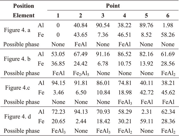
As can be seen from Table 5 and Fig. 7(a), the IMCs layer transfers from the unwelded zone (FeAl) to the flat welded zone (Fe2Al5+FeAl2+FeAl) to the wave interface (α-Al+FeAl3). According to the Gibbs free energy relationship of Al/Fe intermetallic compound, as shown in Fig. 7(b),22) the more negative the Gibbs free energy, the more spontaneous the reaction, the more likely it is to generate. Fe2Al5 has the lowest Gibbs free energy will first form at interface after aluminum alloy pressed into stainless steel, which indicates the elemental chemical reaction as follows.
The pressed aluminum alloy of interface is first to form Fe2Al5:
| \begin{equation}
\text{2Al} + \text{5 Fe (diffusing)} \to \text{Fe$_{2}$Al$_{5}$}
\end{equation}
| (9) |
As Fe content increases, the intermetallic compounds gradually convert to FeAl2:
| \begin{equation}
\text{2Fe$_{2}$Al$_{5}$} + \text{Fe (diffusing)} \to \text{5FeAl$_{2}$}
\end{equation}
| (10) |
The intermetallic compound (FeAl) is formed in situ at the position of the particles of stainless steel in the interface:
| \begin{equation}
\text{Al} + \text{Fe} \to \text{FeAl}
\end{equation}
| (11) |
After the formation of Fe2Al5 by element diffusion, the reaction (1) is exothermic under high pressure at high-speed impact process in small gap, which results a rapid heating and the formation of FeAl3:
| \begin{equation}
\text{Fe$_{2}$Al$_{5}$} + \text{Al} \to \text{FeAl$_{3}$}
\end{equation}
| (12) |
FexAly intermetallic phases are known to be hard and brittle and a common issue for dissimilar welding of aluminum and steel, however the types of intermetallic compounds are different at four zones of the interface, which will directly affect the performance of welded joint, therefore it is very important to understand the formation mechanism of intermetallic compounds.
Figure 8(a) shows a molten steel zone was about 1.5 µm thick in the transition zone and content percentage of point 1 (8.59% Al, 66.56% Fe) had no possible phase, a chemical reaction took place at point 2 (70.24%Al, 21.47%Fe) to form an intermetallic compound (FeAl3), the same phase appeared at interface.23) High-speed collision would cause the metal to heat up and rapid cooling at interface,24) diffusion coefficient of iron atom in the aluminum was much larger than that of aluminum atom in solid steel,25) as seen from Fig. 8(b)–8(d), the iron atom diffuses to a relatively long range into the aluminum alloy, while Al atom could not. Therefor it is indicated that the energy accumulation at interface in high velocity impacting causes the stainless steel to melt, which reduces the diffusion of Fe to form FeAl3, the characteristics of surface metal are very important for the analysis of intermetallic compounds.
3.4 SPH simulation of metal jet
As shown in Fig. 9, aluminum particles wrapped in steel particles agglomerate together to form a beam jet with undulating wavy morphology at a smaller impact angle can obtain a small wavy of interface, the dispersed jet at a relatively large angle gains a bigger wavy interface zone. Jet formed by surface metal to expose the clean surface,26) a form jet has weak ability to remove oxides, the compression and impact of the particle flow produces pit with different sizes to create condition for atomic binding, which increases the instantaneous contact area to form wave interface, wave interface generated under the action of jet indentation.27) Simulated results are agreement with the experiment results, as shown in Fig. 9(c)–9(d). Therefore, the simulation model can accurately reproduce the change of jet state during the impact process, it is estimated that a jet of aluminum particles wrapped in steel particles exists rich-Fe phase, a dispersed jet develops rich-Al phase.

Figure 10(a) shows mechanical property of welded joint. The Vickers hardness of discharge voltage 12 KV close to base metal, the Vickers hardness at transition zone of discharge voltage 15 KV is higher than the unbonded zone about 117 HV, and the maximum value is about 279.9 HV near to the stainless steel. High-velocity impacting of flyer plate makes the metal to be subject to strong compression and generate fine grain, the wide of deformed area is 8 mm in Fig. 2(a), as can be seen in reported,28) Lee confirmed that the intermediate layer was composed of fine Al grain, extremely fine Al–Fe intermetallic compound grain and amorphous phase,29) which leads to different degrees hardening near to interface. The intermetallic compounds also make the hardness of transition zone higher than the aluminum alloy, Yulong LI reported that Fe2Al5 was 121.176 HV, FeAl2 was 120.511 HV, and FeAl3 was 115.319 HV28.30) The fractured position of sample with discharge voltage 12 KV was on the welded seam, while the 15 KV sample fractured on the aluminum alloy, the maximum shear forces were 0.89 KN and 1.38 KN respectively, as shown in Fig. 10(b).

Seen from Fig. 11, welded seam is oval with the width about 2 mm, shear fracture of welded joint of 12 KV is distributed in a lamellar morphology, combination with EDS results as seen in Table 6, white spherical with different sizes distributed on fracture surface are rich-iron intermetallic compounds (Fe3Al, FeAl). The shear fracture of 15 KV welded joint is dominated by dimples with different depths, accompanied by larger impact plastic deformation holes and tearing edges. According to characteristics of metal jet from SPH simulation, it is illustrated that the interface formed by the beam jet generates spherical rich-iron intermetallic compounds, and gains the welded joint with poor connection performance, while the dispersed jet produces rich-aluminum intermetallic compounds (FeAl3), gains the high performance of welded joint.

As shown in Fig. 12, there were some cracks and steel particles gathered by pressed aluminum alloy at transition zone. The trapped jet converts kinetic energy to internal energy to provide energy for metallurgical bonding, however, too much melted metals generated by high-energy compression effect are easy to generate cracks along interface when impact pressure insufficient. High impact energy caused melting,31) crack was the main defect of electromagnetic pulse welding joint,32) therefor reducing impact energy or decreasing impact angle can control the particle flow to fly out of the wave trough along path 1 before the flyer plate pressed into target plate, and eject from path 2, which can effectively avoid the cracks and control the state of the intermetallic compounds.
4. Conclusion
-
(1)
Simulated results by ANSYS software illustrate the key mechanism of producing wavy interface is aluminum alloy pressed into stainless steel in semi-melted state. Parabolic distribution of electromagnetic force and direction changing at both edges of flyer plate generate welded seam seem to be elliptical ring.
-
(2)
The calculated initial impact velocity which can produce jet for welding two metal was 236.5 m/s. With impact angle increasing, gradually formed unwelded zone with gap 9.96 µm, flat welded zone, small wave zone and big wave zone, gray transition zone from 3.79 µm to 14.34 µm. IMCs layer transfers from unwelded zone (FeAl) to flat welded zone (Fe2Al5+FeAl2+FeAl) to wave interface (α-Al+FeAl3), but the wave interface became unnoticeable with impact angle further increases.
-
(3)
Simulated results of SPH offered that the compression and impact effect of particle flow dominate the morphology characteristics of interface. The dispersed jet increased the area of active clean metal and created the condition for atomic binding, mainly formed Al-rich FeAl3, a beam jet formed spherical Fe-rich FeAl which reduced the performance of welded joint and usually broke at the welded seam.
-
(4)
Shear tests validated the failure model at welded seam for specimen set was too much particle Fe-rich phase gathered at interface to decrease the joint performance. Therefore, controlling impact energy makes particle flow of downstream target plate fly out of wave trough before flyer plate pressed into the target plate, which can effectively control intermetallic compounds.
Acknowledgements
This research was funded by the National Science Foundation of China (Grant No. 51805065), and the State Key Laboratory of Advanced Welding and Joining of China (No. AWJ-19M02), and sponsored by Natural Science Foundation of Chongqing (cstc2020jcyj-msxmX0574).
REFERENCES
- 1) J.M. Munoz-Guijosa, G. Nanaumi, K. Ohtani and N. Ohtake: J. Mater. Process. Technol. 243 (2017) 112–122.
- 2) S. Meco, S. Ganguly, S. Williams and N. Mcpherson: J. Mater. Process. Technol. 268 (2019) 132–139.
- 3) G. Ananda Rao and N. Ramanaiah: Mater. Today: Proc. 19 (2019) 902–907.
- 4) M.-N. Avettand-Fènoël, M. Marinova and R. Taillard: Mater. Charact. 153 (2019) 251–260.
- 5) H.H. Geng, L.Q. Sun, G.Y. Li, J.J. Cui, L. Huang and Z.D. Xu: Int. J. Fatigue 121 (2019) 146–154.
- 6) P. Ghosh, S. Patra, S. Chatterjee and M. Shome: J. Mater. Process. Technol. 254 (2018) 25–37.
- 7) S. Mishra, S.K. Sharma, S. Kumar, K. Sagar, M. Meena and A. Shyam: J. Mater. Process. Technol. 240 (2017) 168–175.
- 8) Z.S. Fan, H.P. Yu and C.F. Li: Scr. Mater. 110 (2016) 14–18.
- 9) A.P. Manogaran, P. Manoharan, D. Priem, S. Marya and G. Racineux: J. Mater. Process. Technol. 214 (2014) 1236–1244.
- 10) M. Hahn, C. Weddeling, J. Lueg-Althoff and E. Tekkaya: J. Mater. Process. Technol. 230 (2016) 131–142.
- 11) T. Itoi, A.B. Mohamad, R. Suzuki and K. Okagawa: Mater. Charact. 118 (2016) 142–148.
- 12) R.N. Raoelison, N. Buiron, M. Rachik, D. Haye, G. Franz and M. Habak: J. Mater. Process. Technol. 213 (2013) 1348–1354.
- 13) S.J. Chen and X.Q. Jiang: J. Manuf. Process. 19 (2015) 14–21.
- 14) O. Maloberti, O. Mansouri, D. Jouaffre, M. Hamzaoui, J. Derosiere, N. Buiron, P. Sansen, T. Sapanathan, P. Pelca, M. Rachik, J.P. Leonard, G. Lembrouck, D. Haye and A. Macret: J. Mater. Process. Technol. 266 (2019) 450–473.
- 15) J. Lueg-Althoff, J. Bellmann, S. Gies, S. Schulze, A.E. Tekkaya and E. Beyer: J. Mater. Process. Technol. 262 (2018) 189–203.
- 16) T. Sapanathan, R.N. Raoelison, E. Padayodi, N. Buiron and M. Rachik: Mater. Des. 102 (2016) 303–312.
- 17) T. Lee, A. Nassiri, T. Dittrich, A. Vivek and G. Daehn: Scr. Mater. 178 (2020) 203–206.
- 18) K.N. Salloomi: J. Manuf. Process. 45 (2019) 746–754.
- 19) S.D. Kore, P. Dhanesh, S.V. Kulkarni and P.P. Date: Int. J. Appl. Electromagn. Mech. 32 (2010) 1–19.
- 20) S.H. Chen, G.S. Daehn, A. Vivek, B. Liu, S.R. Hansen, J.H. Huang and S.B. Lin: Mater. Sci. Eng. A 659 (2016) 12–21.
- 21) M. Watanabe and S. Kumai: Mater. Trans. 50 (2009) 2035–2042.
- 22) J.K. Huang, N. Liu, C.C. He, Y. Shi and D. Fan: J. Harbin Eng. Univ. 37 (2016) 837–841.
- 23) L. Shao, Y. Shi, J.K. Huang and S.J. Wu: Mater. Des. 66 (2015) 453–458.
- 24) Z.Y. Lu, W.T. Gong, S.J. Chen, T. Yuan, C.L. Kan and X.Q. Jiang: J. Manuf. Process. 46 (2019) 59–66.
- 25) N. Sridharan, J. Poplawsky, A. Vivek, A. Bhattacharya, W. Guo, H. Meyer, Y. Mao, T. Lee and G. Daehn: Mater. Charact. 151 (2019) 119–128.
- 26) T.H. Wang, H. Sidhar, R.S. Mishr, Y. Hovanski, P. Upadhyay and B. Carlson: Mater. Des. 174 (2019) 107795.
- 27) S. Kakizaki, M. Watanabe and S. Kumai: Mater. Trans. 52 (2011) 1003–1008.
- 28) M. Watanabe, S. Kumai and T. Aizawa: Mater. Sci. Forum 519–521 (2006) 1145–1150.
- 29) K.J. Lee, S. Kumai, T. Arai and T. Aizawa: Mater. Sci. Eng. A 471 (2007) 95–101.
- 30) Y.L. Li, Y.R. Liu and J. Yang: Opt. Laser Technol. 122 (2020) 105875.
- 31) A. Ben-Artzy, A. Stern, N. Frage, V. Shribrman and O. Sadot: Int. J. Impact Eng. 37 (2010) 397–404.
- 32) A. Bouayad, Ch. Gerometta, A. Belkebir and A. Ambari: Mater. Sci. Eng. A 363 (2003) 53–61.