1. Introduction
Carbon nanotubes (CNTs) are tubular nanofibers made of graphene, which is a monolayer of six-membered carbon rings. CNTs are thought to have higher elastic modulus and strength than those of carbon fibers, and the specific gravity of CNTs is comparable to that of carbon fibers.1) In order to utilize the excellent mechanical properties of CNTs, various basic and applied research has been conducted. Most of the research use CNTs dispersed in solvent or resin and the length of CNTs are a few to tens of µm. To take advantage of the excellent mechanical properties of CNTs, it is crucial to achieve both higher volume fraction and unidirectional alignment of CNTs, not randomly dispersed. Besides, it is necessary to develop a technique to keep CNTs straight in resin as possible because the diameter of CNTs is on the nano-order and thus CNTs are easy to bend.
In recent years, research on dry spinning technology for multi-walled CNTs has been reported.2–10) There are two major methods: one is to draw out CNTs from vertically grown CNTs on a substrate, which is called a CNT forest or a CNT array, and then to twist the drawn CNTs for producing continuous spun yarns,2) and the other is to grow CNTs in gas phase and draw the CNTs continuously with twist.4) Figure 1 shows a SEM photograph of a dry-spinnable CNT forest. By pinching one end of the CNT forest and pulling it out horizontally, CNTs can be drawn continuously because of Van der Walls force among CNTs.

The drawn CNT network structure is referred to as CNT web. SEM observation shows that CNTs are aligned in one direction in the drawn direction. Thus, a unidirectionally aligned CNT sheet can be made by winding a CNT web on a mandrel, or a CNT spun yarn can be made by drawing and twisting. These CNT assemblies have the advantage that they can be used as fiber preforms for composite fabrication because the CNT assemblies can be densified while maintaining the unidirectional orientation of CNTs.
It was also reported that untwisted CNT yarns can be made by passing a web drawn from a CNT forest through a die without twisting.10,11) Since CNTs of an untwisted CNT yarn are almost aligned in the axial direction, CNT untwisted yarns are thought to be useful for producing high-strength yarns and composite materials that take full advantage of the higher mechanical performance of CNTs. In addition, acid treatment12) and impregnating binders13) can increase the strength of CNT untwisted yarns; it was reported that the application of binders resulted in >200 GPa of Young’s modulus and >2 GPa of tensile strength.13)
For conventional spun yarns for clothing, the bonding force between filaments composing yarns is weak and so twisting is essential for spinning. Many studies on the mechanical analysis of tensile properties of conventional spun yarns14) were conducted during the 1950s and 1960s, but untwisted yarns were out of scope for the research.
In this study, the tensile properties of CNT untwisted yarns are reported, and an analytical model of tensile properties of CNT untwisted yarns based on a shear lag theory is proposed in order to elucidate the tensile behaviors of CNT untwisted yarns. The results will give suggestions for the improvement of the stiffness and strength of CNT untwisted yarns.
The proposed model also can provide estimation methods of the tensile properties of a single CNT from the tensile properties of untwisted yarns. Thus, the tensile modulus and strength of a single CNT used in this study were estimated from the experimental results.
2. Fabrication of Untwisted Yarns and Their Tensile Properties
2.1 Fabrication of untwisted yarns
The spinnable carbon nanotubes used were multiwalled carbon nanotubes grown on silicon substrates produced by a chemical vapor deposition method using acetylene gas (C2H2) as the raw material and iron chloride (FeCl2) as the catalyst.15) The average diameter and length of a CNT were 37 nm and about 1 mm, respectively.
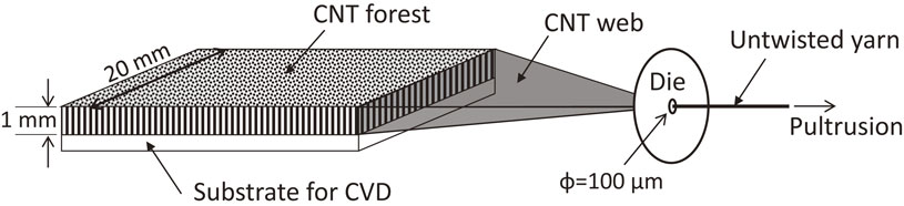
Figure 2 is a schematic of the spinning process of an untwisted yarn. In this study, the die diameter was set to 100 µm. A SEM photograph of an untwisted yarn is shown in Fig. 3. The drawing speed was not strictly controlled because untwisted yarns were drawn by hand, but the drawing speed was around a few cm/s.
The porosity of as-pultruded yarns (hereinafter referred to as As-pultruded) was more than 90% and thus the density was low. Therefore, untwisted yarns were densified by applying ethanol to as-pultruded untwisted yarns and drying. In this study, ethanol was dried in two ways: leaving yarns in air at room temperature for 48 hours (hereinafter referred to as Densified (RT)) or in an electric furnace at 150°C for 3 hours (hereinafter referred to as Densified (HT)). Table 1 summarizes the fabrication conditions and the densities of the untwisted yarns used in this study. In the table, errors are standard deviations.

Table 1 Fabrication conditions of untwisted spun yarn.
To evaluate the tensile properties of untwisted yarns, tensile tests were conducted by using the following method, which was similar to the tensile testing method in JIS R7606, “Carbon fibre – determination of the tensile properties of the single filament specimens”. An untwisted MWNT yarn of 5 cm long was glued at both ends on a U-shaped paper mount with adhesive (cyanoacrylate type) as shown in Fig. 4. The gauge length was set to 15 mm. After a specimen adhered to a paper mount was chucked, the paper mount was cut along the dashed line in the center before the tensile test. The tensile tests were conducted at a crosshead speed of 1 mm/min at room temperature in air. A non-contact extensometer was used to measure elongation. The number of tests was 12 or more in each fabrication condition.

The cross-sectional area was calculated as follows: the cross-sectional shape of an As-pultruded specimen was almost a circle, so the diameter was measured by optical microscope before the test; and the cross-sectional shape of a Densified specimen was distorted from a circle and thus the cross-sectional area was measured from the SEM image of the fracture surface. The linear density of an untwisted yarn of 40 cm long drawn from the same MWNT array used for specimens was measured for each fabrication condition, and the density of a specimen was assumed to be the linear density divided by the cross-sectional area of the specimen.
Examples of stress-strain curves are shown in Fig. 5. The stress-strain curves show slight nonlinearity and the tensile properties were significantly affected by the densification process.
The tensile modulus and tensile strength of the specimens are shown in Fig. 6. In the figure, the error bars are standard deviations and the elastic moduli were defined as slopes in the range of 0.05% to 0.25% of strain. In order to discuss the effect of density of untwisted yarns, specific tensile modulus and specific tensile strength are shown in Fig. 7. The difference in specific properties between the As-pultruded and Densified specimens suggests that the improvement in tensile properties of Densified specimens was not simply caused by the differences in density.
The scatter band of specific values shown in Fig. 7 is smaller than that of absolute values shown in Fig. 6. Since there was large variation in density of the produced yarns (see Table 1), normalizing the absolute values by the specific density resulted in smaller scatter in Fig. 7.
Figure 8 shows typical SEM photographs of fractured portions of specimens. The fracture portion of the As-pultruded specimen had an appearance that CNTs slid each other. For Densify (RT) and Densified (HT) specimens, the fracture portions had much flatter fracture surfaces than that of the As-pultruded specimen. Since the length of CNTs used in this study was about 1 mm and the maximum length of the slip region in the fracture portion of the as-pultruded yarn was about 500 µm, the fracture mode of As-pultruded was probably the slippage of CNTs. On the other hand, the pull-out length of CNT bundles at the fracture surfaces of Densify (RT) and Densified (HT) was at most 100 µm. The shorter pull-out length implies that the fracture mode of Densified was CNT breakage. The discussion suggests that the increase in specific strength by densification was brought by the prevention of slippage of CNTs as a result of densification.
3. Analytical Model of Untwisted Yarn
3.1 Derivation of analytical equations for tensile properties based on a shear-lag model
In this study, a CNT untwisted yarn is modelled as a CNT surrounded by an equivalent homogeneous medium as shown in Fig. 9. When a tensile stress σapp is applied to an untwisted yarn, the load transfer from the equivalent homogeneous medium to the CNT is assumed to be made from the shear stress acting on the slipping regions near the both ends of the CNT. This assumption is the so-called shear lag model,16) in which the shear stress acting on the surface of the CNT and the axial normal stress of the CNT17) are shown in Fig. 10.
In Fig. 10, lf is the fiber length of the CNT, lt is the total length of the slipping regions near both ends of the CNT, σf is the axial normal stress on the CNT, τs is the shear stress acting on the surface of CNTs, and df is the diameter of the CNT.
Since the shear force acting on the surface of the CNT at the sliding regions results from the Van der Waals force between CNTs, the shear force can be almost determined by the distance between CNTs, i.e., the volume fraction of CNTs in the untwisted yarn.11) Therefore, the magnitude of the shear stress acting on the slipping region can be assumed to be constant regardless of the position. The magnitude of the shear stress acting on the slipping region is designated as τvdw.
The stress σapp causes strain εyarn of the untwisted yarn, and thus the tensile modulus Eyarn of the untwisted yarn is given by the following equation.
| \begin{equation}
E_{\textit{yarn}} = \frac{\sigma_{\textit{app}}}{\varepsilon_{\textit{yarn}}}
\end{equation}
| (1) |
The following relationship exists with respect to the stress distribution given by the shear lag model.
| \begin{equation}
\overline{\sigma_{f}} = \frac{1}{l_{f}}\int_{0}^{l_{f}}\sigma_{f} dx = \sigma_{f}^{\textit{max}} \left(1 - \frac{l_{t}}{2l_{f}}\right)
\end{equation}
| (2) |
| \begin{equation}
\sigma_{f}^{\textit{max}} = \frac{4\tau_{\textit{vdw}}}{d_{f}} \cdot \frac{l_{t}}{2} = \frac{2\tau_{\textit{vdw}}l_{t}}{d_{f}}
\end{equation}
| (3) |
where
$\overline{\sigma _{f}}$ is the average value of the axial normal stress acting on the CNT.
Since the strain $\varepsilon _{f}^{\textit{stick}}$ of the stick region of the CNT is equal to the strain εyarn of the untwisted yarn, Hooke’s law gives the following equation.
| \begin{equation}
\sigma_{f}^{\textit{max}} = \varepsilon_{f}^{\textit{stick}}E_{f} = \varepsilon_{\textit{yarn}}E_{f}
\end{equation}
| (4) |
where
Ef is the tensile modulus of the CNT when it is regarded as a solid bar.
The force equilibrium between external and internal forces gives
| \begin{equation*}
\sigma_{\textit{app}}\cdot A_{\textit{yarn}} = \overline{\sigma_{f}}\cdot (V_{pf}A_{\textit{yarn}})
\end{equation*}
|
where
Ayarn is the cross-sectional area of the untwisted yarn and
Vpf is the volume packing fraction of CNT in the untwisted yarn. Dividing both sides by
Ayarn gives
| \begin{equation}
\sigma_{\textit{app}} = \overline{\sigma_{f}}\cdot V_{pf}
\end{equation}
| (5) |
Eliminating εyarn, $\overline{\sigma _{f}}$, $\sigma_{f}^{\textit{max}}$ and lt from eqs. (1)–(5), and solving for Eyarn, we obtain
| \begin{equation}
E_{\textit{yarn}} = E_{f} \left(\frac{l_{f}V_{pf}\tau_{\textit{vdw}} + \sqrt{l_{f}V_{pf}\tau_{\textit{vdw}} (l_{f}V_{pf}\tau_{\textit{vdw}} - d_{f}\sigma_{\textit{app}})}}{2l_{f}\tau_{\textit{vdw}}}\right)
\end{equation}
| (6) |
Equation (6) is the secant modulus of the untwisted yarn. If lf, df, Vpf, and τvdw are known, the secant modulus can be calculated as a function of the applied stress σapp.
Similarly, the solution for lt can be obtained as the follow equation.
| \begin{equation}
l_{t} = l_{f} - \frac{\sqrt{l_{f}V_{pf}\tau_{\textit{vdw}} (l_{f}V_{pf}\tau_{\textit{vdw}} - d_{f} \sigma_{\textit{app}})}}{V_{pf}\tau_{\textit{vdw}}}
\end{equation}
| (7) |
Development of slipping regions near both ends of each CNT of an untwisted CNT yarn under tensile loading is discussed using the shear-rag model and eq. (7). At the beginning of the loading, the length of the slipping region is short because the stress exerted on each CNT is small; substituting σapp = 0 into eq. (7) gives lt = 0.
Increasing the applied load leads to the increase of the length of the slipping region because the magnitude of the shear stress acting on the slipping region is constant.
If the shear stress acting on the slipping region is small, further increase of the applied load leads to the entire slippage of each CNT, resulting in yarn failure due to slippage. In contrast, if the shear stress acting on the slipping region is sufficiently large, the normal stress acting on the stick region reaches the tensile strength of CNT before the entire slippage of each CNT, resulting in yarn failure due to CNT breakage.
Thus, it is presumed that the development of the slippage regions of CNTs under tension is the reason of the mild nonlinearity in the stress-strain diagram of an untwisted yarn while a CNT can be regarded as an elastic body, and the transition of the failure mode of untwisted yarns from slippage to CNT breakage is caused by the increase in van der Waals force between CNTs as result of densification, although it is necessary to conduct in-situ observation of tensile behaviors of untwisted yarns in a high-resolution SEM in order to prove the above discussion.
3.2.2 Estimation of the tensile modulus of a CNT
Using the proposed model in Sec. 3.2.1, an estimation method for the tensile modulus of a CNT from the tensile properties of untwisted yarns is proposed in this section.
Equation (6) expresses the secant modulus of an untwisted yarn, and eq. (6) includes a term of shear stress acting on the slipping region of CNTs. The magnitude of this shear stress is determined by the distance between CNTs because the shear stress is caused by Van der Waals force as described above, but it is difficult to estimate the shear stress.
Thus, let’s consider the initial slope of the stress-strain diagram of an untwisted yarn. In eq. (6), the following equation is obtained if σapp → 0,
| \begin{equation}
E_{\textit{yarn}} = E_{f}V_{pf}
\end{equation}
| (8) |
The term of shear stress acting on the slipping region disappears because there is almost no slipping region at the beginning of the loading as discussed in section 3.2.1, and normal stress acts almost uniformly along the entire length of the CNT.
Equation (8) enables us to estimate the tensile modulus of a CNT from the initial slope of the stress-strain diagram of an untwisted yarn and the volume packing fraction of CNT of the untwisted yarn without estimating or assuming the shear stress acting on the slipping region of CNTs.
Therefore, the initial moduli of untwisted yarns for all experimental results are plotted as a function of the volume packing fraction as shown in Fig. 11. The initial moduli in Fig. 11 were determined as the slopes in the range of 0.05% strain to 0.25% strain, which is the same definition of elastic modulus in Section 2.2.2, because it is difficult to determine the accurate initial modulus from an experimental stress-strain diagram. Note that the elastic modulus determined in the range of 0.05% strain to 0.25% strain approximates the initial modulus because the nonlinearity up to 0.25% strain is small.

Figure 11 shows that there is a linear relation between the initial moduli and CNT volume packing fractions, and thus supports the validity of eq. (8). Linear regression of the results in Fig. 11 gives an estimate of the Young’s modulus of a CNT to be 197 GPa, where a CNT is considered to be a solid bar. The estimate will be compared with experimental results in Section 3.2.4. In Fig. 11, the initial moduli of As-pultruded yarns showed lower values than the regression line. In this study, it is assumed that a CNT is surrounded by homogeneous media, but the assumption is not necessarily valid for As-pultruded yarns because the higher porosities of As-pultruded yarns of more than 90% would result in insufficient load transfer between CNTs.
3.2.3 Estimation of the tensile strength of a CNT
An estimation method for the tensile strength of a CNT from the tensile properties of untwisted yarns is described in this section. Let’s consider the transition point of the failure mode of untwisted yarns from slippage into CNT breakage. The normal stress distribution in a CNT at the transition is shown in Fig. 12. In this case, slippage occurs throughout the entire length of a CNT, but the maximum normal stress at the center of the CNT reaches the tensile strength of the CNT, σfu.
The average normal stress acting on the CNT, $\overline{\sigma _{f}}$, is
| \begin{equation}
\overline{\sigma_{f}} = \frac{\sigma_{fu}}{2}
\end{equation}
| (9) |
Hereafter, the tensile strength of the untwisted yarn when the fracture mode transits from slippage into CNT breakage is denoted as $\sigma _{B}^{\textit{trans}}$. Substituting eq. (9) into eq. (5) gives the following equation.
| \begin{equation}
\frac{\sigma_{B}^{\textit{trans}}}{V_{pf}} = \frac{\sigma_{fu}}{2}
\end{equation}
| (10) |
The above equation does not include the term of shear stress acting on the slipping region, and thus the tensile strength of a CNT, σfu, can be estimated only from the tensile strength and CNT packing fraction of the untwisted yarn when the failure mode transits.
The relationship between the tensile strength of every untwisted yarn divided by the CNT packing fraction and the volume packing fraction of CNT are plotted in Fig. 13. Figure 13 shows that $\sigma _{B}^{\textit{trans}}/V_{pf}$ is around 950 MPa. Thus, the tensile strength of a CNT can be estimated to be around 1.9 GPa from eq. (10).
The estimated results are compared with the experimental results in the next section.
3.2.4 Comparison with experimental results
Table 2 lists the tensile properties of a CNT evaluated by tensile tests in SEM18) where CNTs were synthesized under the almost same conditions as those used in this study, and the tensile properties of a CNT estimated from the tensile properties of composites using the rule of mixture,19) where the composites were prepared by impregnating epoxy into spun yarns obtained from CNT forests.

Table 2 Tensile properties of CNT evaluated by various methods.
The tensile modulus of a CNT estimated from the tensile properties of untwisted yarns shows good agreements with the two experimental results, indicating that the proposed method is useful to estimate the tensile modulus of a CNT.
The tensile strength of a CNT estimated from the tensile properties of untwisted yarns was about 1.4 times higher than that estimated from the tensile tests of composites using the rule of mixture, and was about 1/3 of that estimated from the tensile tests of CNTs in SEM. In the case of the tensile tests in SEM, the gauge length was 11–12 µm. This extremely short gauge length probably led to the higher tensile strength. In addition, the proposed analytical model is a simple model in which a CNT is embedded in a homogeneous medium as shown in Fig. 9. The simplification would cause the error of the estimate of the tensile strength of a CNT because the idealization adopted in this study might not be appropriate when the slipping region is large. Further studies are needed to accurately estimate the tensile strength of a CNT using the tensile strengths of untwisted yarns.
3.2.5 Estimation of shear stress acting on the slipping region
As discussed in the previous sections, the shear stress τvdw acting on the slipping region has a significant effect on the tensile properties. Thus, it is useful to estimate the shear stress acting on the slipping region. In this section, the shear stress τvdw for the untwisted yarns after densification, which had higher mechanical properties, is estimated.
One method for estimating τvdw is to regress the change of secant modulus for stress–strain curves in eq. (6). The method will, however, make inaccurate estimates of τvdw because the nonlinearity of stress–strain curves for densified untwisted yarns were small and the change of the secant modulus was not significant as shown in Fig. 5.
Therefore, we used a model proposed by Curtin20) for estimating the shear stress τvdw. The model focused on the tensile strength of an unidirectionally aligned fiber reinforced ceramic, and the strength of the reinforcing fibers was assumed to obey Weibull distribution. Based on the assumption, Curtin derived a relationship between the tensile strength of reinforcing fibers and the mean pull-out length of reinforcing fibers found in the fracture surface. If the shape parameter is sufficiently large, the following relation is obtained.
| \begin{equation}
\langle L\rangle = \frac{\sigma_{0}r_{f}}{4\tau_{s}}
\end{equation}
| (11) |
where ⟨
L⟩ is the mean pull-out length of reinforcing fibers found in the fracture surface, σ
0 is the tensile strength of the reinforcing fiber,
rf is the fiber radius, and τ
s is the shear stress acting on the fiber surface.
If an untwisted yarn is regarded as a unidirectional fiber-reinforced composite, we can obtain a rough estimate of the interfacial shear strength τvdw from eq. (11) by substituting the mean pull-out length, 10–25 µm, which were determined from a SEM image in Fig. 8, and the tensile strength of a CNT, 1.9 GPa, which was estimated in Section 3.2.3. The estimated value of τvdw was 0.35–0.88 MPa. Considering the fact that the shear stress acting between two carbon nanotubes was estimated to be 4.0 MPa21) when the two carbon nanotubes were slid across each other experimentally, the rough estimate of τvdw in the present study seems to be reasonable.