Mechanics of Materials
Prediction and Experimental Verification of the Critical Fracture Blank Holder Force for Deep Drawing of Box-Shaped Parts
2022 Volume 63 Issue 11 Pages 1541-1549

Details
2022 Volume 63 Issue 11 Pages 1541-1549
In this paper, the deformation law of box-shaped parts drawing was analyzed, and the mathematical expression for calculating the critical fracture blank holder force (BHF) was deduced. In order to determine the fracture parameters of 08Al sheet, notched specimen tensile tests were conducted, the full-field strain of the specimens from deformation to fracture was obtained by the digital image correlation (DIC) technology. The evolution law of the stress triaxiality and Lode parameter with plastic deformation was obtained, and the fracture parameters of the modified Mohr-Coulomb (MMC) fracture criterion were fitted by the least squares method. The finite element (FE) simulation model coupled with MMC ductile fracture criterion was established to simulate the fracture behavior of sheet. The reliability of theoretical calculation was evaluated by FE simulation and experiments under various process conditions. The results demonstrated that the prediction of the critical fracture BHF by theoretical calculation and FE simulation were both partial safety predictions and all fracture earlier than the tests. In the theoretical calculation, when the flange shrinkage rate was 0.19, the critical BHF was the smallest, and the error was 17.5% compared with the tests, the theoretical calculation was closer to the test results. The theoretical calculation and FE simulation coupled with ductile fracture criterion provide a reference value for predicting the critical fracture BHF and intelligent control in actual production.

Deep drawing is a sheet forming process in which the sheet material flows into the female die under the action of the punch. It has the technical advantages of high material utilization rate, high production efficiency and low energy consumption, and is widely used in aerospace, automobile manufacturing, household appliances, kitchen appliances and other industrial fields.1–3) Driven by the background of lightweight design and green manufacturing, higher requirements are put forward for the structural complexity and mechanical properties of stamping parts.4)
Wrinkling instability is an unstable phenomenon that often occurs during the drawing process, and the key to analyze the wrinkling problem is the control of BHF. Qin et al.5) deduced the calculation model of critical BHF for wrinkling instability in the process of deep drawing through mechanical analysis, and determined that the critical BHF was not constant and changed with the progress of deep drawing. Subsequently, the research work of many scholars also focused on variable blank holder force (VBHF). Sheng et al.6) developed an adaptive simulation strategy to adjust the BHF continuously during the simulation process, which was applied to the drawing process successfully for tapered and non-axisymmetric parts. Kitayama et al.7) proposed a VBHF optimization method, and carried out multi-objective optimization by response surface method. The effectiveness of this method was verified by numerical simulation and experiment. Xie et al.8) presented a method to optimize the BHF based on radial basis function, and determined the optimal loading path of VBHF by grey relational analysis. The experimental results showed that the optimized BHF path reduced the wrinkling of formed parts and made the plastic deformation more uniform. Zhang et al.9) proposed a novel double-ring blank holder method to eliminate wrinkling by applying independent BHF on different flange areas. The application of VBHF during deep drawing process has become a consensus, but at present many researches focus on numerical simulation, control algorithms, experimental trial and error. There is little research on theoretical analysis of plastic deformation, which may be caused by the difficulty of analyzing complex plastic deformation process and wrinkling mechanism from the theoretical point of view.
Too little BHF will lead to wrinkling instability, and too much BHF will lead to fracture. Sheet metal forming is a complex process with geometric, material and boundary nonlinearity, so it is difficult to accurately predict fracture.10) With the wide application of FE simulation technology, the numerical simulation coupled with fracture criterion provides a new solution to investigate the fracture behavior of materials. In recent decades, many scholars have proposed a variety of ductile fracture criteria based on different related variables, such as the classic Cockcroft criterion, Rice criterion, Oh criterion and OY criterion, as well as the popular MMC criterion and Lou-huh criterion in recent years.11–16) In addition, many scholars have done numerous studies on the applicability of the above fracture criterion. Xue et al.17) embedded the normalized Cockcroft and Latham criterion into the user subroutine in ABAQUS software to simulate the damage evolution of the bend, and the experimental results verified its applicability, which provided a new strategy for predicting the fracture trend of the bend. Li et al.18) employed five classical ductile fracture criteria to simulate the hot stamping of B1500HS steel and found that the simulation results based on Oyane and Brozzo ductile fracture criteria were close to the test. Moreover, the fracture threshold calculated by fitting and modifying through regression analysis had good reliability and practicability. Hossein et al.19) calibrated the parameters of MMC fracture criterion through multiple tensile tests and analyzed the fracture behavior of the AA6061-T6 aluminum alloy sheet during the U-bending process, the error of the predicted fracture location was about 2% compared with experimental results. Cheng et al.20) modified the material parameters in the Lou-Huh model based on an optimization algorithm by exploring the variation laws of stress triaxiality, Lode parameter and stress ratio under three deformation conditions. The experimental results showed that the improved Lou-Huh model was more suitable for predicting the ductile fracture behavior of DP590 steel plates. The stress triaxiality and Lode parameter are key factors in the calculation of fracture parameters as reflected in several criteria, and it is significant to explore their evolutionary laws to improve the accuracy of fracture criteria. With the development of simulation technology, the proposal and optimization of new fracture criteria, it has become a consensus and trend to analyze the fracture behavior of specific forming processes through coupling with fracture models.
During deep drawing, the metal material in the flange area flows to the center of the female die with the movement of the punch. In the process of metal flow, the sheet material shrinks tangentially under the action of compressive stress, and is prone to wrinkling instability. Appropriate BHF can effectively prevent wrinkling, but too much will lead to fracture. In this paper, based on the theory of sheet plastic deformation, the theoretical model of the critical fracture BHF in the drawing process of box-shaped parts was presented, and the simulation model coupled with MMC ductile fracture criterion was established. The applicability of theoretical calculation model and simulation model was verified through process experiments. Whether from the theoretical analysis point of view or numerical simulation point of view, it provides a reference value for evaluating the critical fracture BHF during deep drawing in practical production.
In the process of sheet metal deep drawing, the fracture often occurs in the force transmission area of the straight wall, especially the tangent of the straight wall and the punch fillet, which is generally the most prone to fracture. Therefore, it is mainly to investigate the force characteristics of the force transmission area to evaluate the bearing capacity of the sheet at the moment of fracture. In the force transmission region, tangential compressive deformation is ignored, and the deformation can be regarded as a state of plane strain, the tangential strain εθ = 0. It is assumed that the anisotropy is planar isotropy and normal anisotropy, according to the normal principle of plastic flow:
| \begin{equation} \text{d}\varepsilon_{\theta} = \frac{\text{d}\bar{\varepsilon}}{\text{d}\bar{\sigma}}(\sigma_{\theta} - \sigma_{z}) \end{equation} | (1) |
During deep drawing, the normal stress of the sheet metal in the straight wall area can be ignored, so σt = 0, dεθ = 0. It can be obtained from eq. (1):
| \begin{equation} \sigma_{\theta} = \frac{r}{1 + r}\sigma_{z} \end{equation} | (2) |
Radial and tangential stresses are coincident with the main axis direction, according to the anisotropic yield criterion:
| \begin{equation} \sigma_{z} = \frac{1 + r}{\sqrt{1 + 2r}}\bar{\sigma} \end{equation} | (3) |
Under simple loading conditions, the equivalent strain can be expressed as:
| \begin{equation} \bar{\varepsilon} = \frac{1 + r}{\sqrt {1 + 2r}}\sqrt{\varepsilon_{z}^{2} + \frac{2r}{1 + r}\varepsilon_{z}\varepsilon_{\theta} + \varepsilon_{\theta}^{2}} \end{equation} | (4) |
Under the condition of plane strain, bring εθ = 0 into eq. (4), the thick strain can be expressed as εt = −εz according to the principle of constant volume, then:
| \begin{equation} \left\{ \begin{array}{l} \varepsilon_{z} = \dfrac{\sqrt{1 + 2r}}{1 + r}\bar{\varepsilon}\\ \varepsilon_{t} = -\dfrac{\sqrt{1 + 2r}}{1 + r}\bar{\varepsilon} \end{array} \right. \end{equation} | (5) |
The instantaneous thickness during deep drawing is obtained as follows:
| \begin{equation} t = t_{0}e^{\varepsilon_{t}} = t_{0}\exp \left(-\frac{\sqrt{1 + 2r}}{1 + r}\bar{\varepsilon}\right) \end{equation} | (6) |
Under the condition of the power-exponential strengthening material model, the force per unit length of the box cross-section is obtained:
| \begin{equation} F = t\sigma_{z} = \frac{1 + r}{\sqrt{1 + 2r}}\bar{\sigma}t_{0}\exp \left(-\frac{\sqrt{1 + 2r}}{1 + r}\bar{\varepsilon} \right) \end{equation} | (7) |
Take dF = 0 as the critical instability condition, differentiate eq. (7) and the constitutive model at the same time, the strain strength at the critical instability moment can be obtained:
| \begin{equation} \bar{\varepsilon}_{0} = \frac{1 + r}{\sqrt{1 + 2r}}n \end{equation} | (8) |
Bring eq. (8) into eq. (7), the expression of the bearing capacity per unit length of the box cross section can be obtained:
| \begin{equation} \sigma_{\lim} = K \left(\frac{1 + r}{\sqrt{1 + 2r}}\right)^{n + 1}\left(\frac{n}{e}\right)^{n} \end{equation} | (9) |
In the process of box drawing, the deformation degree of the flange corner area is much larger than that of the straight edge area, so the area most prone to fracture in the process of box drawing is the place where the straight wall of corner area is tangent to the fillet of punch. Therefore, to evaluate the bearing capacity of the box-shaped parts during the deformation process, it is only necessary to calculate the force in the corner area. In the process of deep drawing, with the movement of the punch, the metal sheet in the flange area flows into the female die cavity, and the stress condition is shown in Fig. 1.

Schematic diagram of sheet metal flowing through the fillet of die.
As indicated in Fig. 1, the axial tensile stress σz in the straight wall transfer zone is mainly composed of the following components:
(1) Radial tensile stress σρ required for plastic deformation of metal materials in the flange area;
(2) The frictional resistance at the fillet needs to be overcome during sheet metal flow. The larger the wrapping angle between the sheet and the die, the greater the frictional resistance. The tensile stress required for the sheet to bypass the fillet can be expressed as:
| \begin{equation} \sigma'_{z} = \sigma_{\rho}{e^{\mu \alpha}}\approx (1 + 1.6\mu) \sigma_{\rho} \end{equation} | (10) |
(3) Bending deformation occurs when the sheet metal bypasses the fillet of the die, and the resulting bending resistance is:21)
| \begin{equation} \sigma_{w} = \frac{t_{0}}{2r_{1} + t_{0}}\sigma_{b} \end{equation} | (11) |
Thus, the tensile stress in straight wall area $\sigma_{z} = \sigma '_{\text{z}} + \sigma_{w}$. To avoid fracture during deep drawing, it is necessary to meet σz ≤ σlim. In other words, when the value of the tensile stress σz in the straight wall area is equal to the value of the ultimate strength σlim of the material, the BHF at that time is the critical BHF for fracture.
Due to the non-axisymmetricity, the deformation characteristics of box-shaped parts in the drawing process are more complicated than those of axisymmetric parts. In consideration of simplifying the theoretical analysis, it is often assumed that the sheet deformation behavior in the flange corner area is similar to that in the deep drawing of axisymmetric parts, while the sheet deformation in the straight edge area is similar to that in the bending of flat plates. However, in the actual deformation process, the metal in the corner area shrinks circumferentially under the action of compressive stress, the flow resistance in each region of the flange is different, and the difference in flow rate induces the generation of shear stress. The stress condition in flange area is shown in Fig. 2.

The stress condition in flange area of box-shaped parts.
Uneven deformation in the flange area leads to different sizes of shear stress in each region, so there must be a dividing line of zero shear stress in the deformation area, and the direction of shear stress on both sides of the dividing line is opposite, that is θ = 0, τρθ = 0. For box-shaped parts, the position when the shear stress is zero, θ0 can be expressed by the following equation:
| \begin{equation} \theta_{0} = \frac{\pi B}{2(A + B)} \end{equation} | (12) |
The zero line of shear stress divides the flange area into two areas, and the solution method is the same. The radial stress at any point in flange corner areas (0 ≤ θ ≤ θ0, r0 ≤ ρ ≤ Rw) can be expressed as:22)
| \begin{equation} \sigma_{\rho} = \frac{2K}{\sqrt{3}n}\left(R_{w}\sqrt{\frac{2(1 + r)}{1 + 2r}}\ln \frac{R_{0}}{R_{w}} \right)^{n}\left[\sqrt{1 - \left(\frac{m\theta}{\theta_{0}}\right)^{2}}{} - \frac{m}{2\theta_{0}} \right]\left(\frac{1}{\rho^{n}} - \frac{1}{R_{w}^{n}} \right) + \frac{\mu Q}{(A + B + \pi R_{w})t_{0}} \end{equation} | (13) |
m is the shear stress coefficient in zone I, the value can be expressed:
| \begin{equation} m = \frac{1}{\sqrt{1 + \biggl[\cfrac{A + B}{\pi B} + \cfrac{n}{(n + 1)B}\biggl(\cfrac{R_{w}^{n + 1} - \rho^{n + 1}}{R_{w}^{n} - \rho^{n}} \biggr) \biggr]^{2}}} \end{equation} | (14) |
According to eq. (13), it is known that when θ = 0, ρ = r0, the radial tensile stress is maximum, so the maximum tensile stress in the drawing process is:
| \begin{equation} \sigma_{\rho \max} = \frac{2K}{\sqrt{3}n}\left(R_{w}\sqrt{\frac{2(1 + r)}{1 + 2r}} \ln \frac{R_{0}}{R_{w}} \right)^{n}\left[1 - \frac{m}{2\theta_{0}} \right]\left(\frac{1}{r_{0}{}^{n}} - \frac{1}{R_{w}^{n}} \right) + \frac{\mu Q}{(A + B + \pi R_{w})t_{0}} \end{equation} | (15) |
Thus, the critical fracture BHF during deep drawing of box-shaped parts can be derived as:
| \begin{equation} Q_{\text{fra}} = \frac{t_{0}}{\mu}(A + B + \pi R_{w}) \left\{ \frac{\sigma_{\lim} - \sigma_{w}}{1.6\mu} - \frac{2K}{\sqrt{3}n}\left( R_{w} \sqrt{\frac{2(1 + r)}{1 + 2r}} \ln \frac{R_{0}}{R_{w}} \right)^{n}\left[1 - \frac{m}{2\theta_{0}} \right]\left(\frac{1}{r_{0}{}^{n}} - \frac{1}{R_{w}^{n}} \right) \right\} \end{equation} | (16) |
The traditional numerical simulation methods are unable to determine the initiation of fracture, and the application of numerical simulation coupled with fracture criterion has become a common means of simulating fracture problems in forming processes in recent years. In this paper, based on the material fracture model of ABAQUS simulation platform, the drawing process of box-shaped parts was simulated by coupling with MMC ductile fracture criterion. Under the Miss yield criterion, MMC fracture criterion can be expressed as:15)
| \begin{equation} \bar{\varepsilon}_{f} = \left\{ \frac{K}{c_{2}}\left[\sqrt{\frac{1 + c_{1}^{2}}{3}} \cos \left(\frac{\bar{\theta}\pi}{6} \right) + c_{1}\left(\eta + \frac{1}{3}\sin \left( \frac{\bar{\theta}\pi}{6} \right)\right)\right] \right\}^{-\frac{1}{n}} \end{equation} | (17) |
The Lode angle parameter $\bar{\theta }$ satisfies the following relationship:
| \begin{equation} \sin \left(\frac{\bar{\theta}\pi}{6}\right) = - \frac{L}{\sqrt{L^{2} + 3}} \end{equation} | (18) |
Equation (18) is brought into eq. (17):
| \begin{equation} \bar{\varepsilon}_{f} = \left\{ \frac{K}{c_{2}} \left[\sqrt{\frac{1 + c_{1}^{2}}{L^{2} + 3}} + c_{1}\left(\eta - \frac{L}{3\sqrt{L^{2} + 3}} \right) \right]\right\}^{-\frac{1}{n}} \end{equation} | (19) |
Obviously, the fracture strain in MCC ductile fracture criterion is a function of stress triaxiality and Lode parameter. In order to obtain the unknown fracture parameters, it is necessary to investigate the interaction law between fracture strain, stress triaxiality and Lode parameters.
3.1 Tensile testsThe material used in this paper is 08Al cold-rolled steel with a thickness of 1 mm. 08Al is a high-quality carbon structural steel, which is widely used in the stamping and forming process of parts. Its chemical composition is shown in Table 1. The dog bone specimen shown in Fig. 3 was designed to test the mechanical properties. The anisotropy of the material was tested by cutting the samples at 0°, 45° and 90° to the rolling direction by EDM. The tensile tests of each specimen were carried out at a strain rate of 0.004 s−1 employing a 100 kN universal material testing machine.


Tensile tests of dog bone specimens.
The mechanical property parameters of 08Al sheet were obtained by fitting the stress-strain curves adopting the power exponential material hardening model and Hill48 anisotropic yielding theories, as shown in Table 2.

From eq. (17), it can be seen that there are only 2 unknown parameters in the MMC ductile fracture criterion, so 2 sets of data at different stress states are needed to calibrate the fracture parameters. In view of improving the solution accuracy and obtaining mechanical property parameters over a wide range of stress triaxiality, it is common to design notched specimens with different shapes for tensile testing.23,24) In this paper, 6 groups of notched specimens representing different stress states were designed, including triangular specimens (TRI1, TRI2), shear specimens (SHE1, SHE2), and circular arc specimens (ARC1, ARC2), whose specimen shapes, sizes and numbers are shown in Fig. 4.

Notched specimens (mm).
In order to acquire the similar deformation rate, the tensile speed of circular and triangular specimens was 12 mm/min, and that of shear specimens was 5 mm/min. Before the test, the samples needed to be cleaned with alcohol, and then sprayed with white and black paint in turn to obtain speckle after air-drying, and the time interval between the two spraying is about 20 minutes. The DIC technology was adopted to detect the whole process from the beginning of deformation until fracture in real time, and obtained the strain evolution law during the whole deformation process.
3.2 Calibration of fracture parametersIn the process of sheet metal deep drawing, the thickness stress is very small and can be ignored. It is assumed that the stress state is plane stress state and the anisotropy is planar isotropy and normal anisotropy, according to Hill48 anisotropic yield criterion, the expressions of equivalent stress and equivalent strain can be obtained:
| \begin{equation} \left\{ \begin{array}{l} \bar{\sigma} = \sqrt{\dfrac{3(1 + r)}{2(2 + r)}} \sqrt{\sigma_{1}^{2} - \dfrac{2r}{1 + r}\sigma_{1}\sigma_{2} + \sigma_{2}^{2}}\\ \bar{\varepsilon} = \sqrt{\dfrac{2(1 + r)(2 + r)}{3(1 + 2r)}} \sqrt{\varepsilon_{1}^{2} + \dfrac{2r}{1 + r}\varepsilon_{1}\varepsilon_{2} + \varepsilon_{2}^{2}} \end{array} \right. \end{equation} | (20) |
Set stress ratio α = σ2/σ1, the stress triaxiality and Lode parameter can be expressed as:
| \begin{equation} \left\{ \begin{array}{l} \eta = \dfrac{\sigma_{m}}{\bar{\sigma}} = \dfrac{1 + \alpha}{3\sqrt{\alpha^{2} - \alpha + 1}}\\ L = \dfrac{2\sigma_{2} - \sigma_{1} - \sigma_{3}}{\sigma_{1} - \sigma_{3}} = 2\alpha - 1 \end{array} \right. \end{equation} | (21) |
Set strain ratio β = ε2/ε1, under simple loading conditions, it can be obtained from the incremental theory:
| \begin{equation} \alpha = \frac{(1 + r)\beta + r}{1 + (1 + \beta)r} \end{equation} | (22) |
Obviously, under simple loading conditions, the strain field can be transformed into a stress field, and the variable stress triaxiality and Lode parameter can be represented by the strain field obtained by the DIC system, as shown in Fig. 5. In the DIC post-processing system, the instantaneous principal strain of the fracture points can be extracted, and the fracture related state variables such as stress triaxiality and Lode parameter at any time can be obtained by combining eqs. (21)–(22). The distribution laws of stress triaxiality, Lode parameter and equivalent plastic strain are shown in Fig. 6.

The strain distribution of notched specimens in DIC.

Evolution laws of stress triaxiality and Lode parameter of notched specimens.
It can be seen from Fig. 6 that the stress triaxiality and Lode parameter are unstable and change continuously with the deformation process, and it is difficult to express it with a general function. Scholars generally used the averaging process for the parameters that evolve with the deformation process,25) such as eq. (23):
| \begin{equation} \left\{ \begin{array}{l} \eta_{\textit{avg}} = \dfrac{1}{\bar{\varepsilon}_{f}}\displaystyle\int_{0}^{\bar{\varepsilon}_{f}} \eta (\varepsilon_{p})\text{d}\varepsilon_{p}\\ L_{\textit{avg}} = \dfrac{1}{\bar{\varepsilon}_{f}}\displaystyle\int_{0}^{\bar{\varepsilon}_{f}} L(\varepsilon_{p}) \text{d}\varepsilon_{p} \end{array} \right. \end{equation} | (23) |
The evolution laws of stress triaxiality and Lode parameter with plastic deformation in Fig. 6 are averaged by eq. (23). The fracture related state variables are obtained, as shown in Table 3.

By using the minimum fitting method, the MMC ductile fracture criterion (eq. (19)) is fitted with the data in Table 3, and the dimensionless fracture parameters c1 and c2 are obtained as 0.1073 and 258, respectively. According to eq. (21), the stress triaxiality and Lode parameter can be expressed by the common unique variable stress ratio, so the stress triaxiality must also be a function of the Lode parameter. Therefore, when the fracture parameters c1 and c2 are known, the MMC ductile fracture criterion can be converted from a three-dimensional ductile fracture surface $(\bar{\varepsilon }_{f},\eta ,L)$ to a two-dimensional fracture curve $(\bar{\varepsilon }_{f},\eta )$. Under the plane stress condition, the stress triaxiality from −1/3 to 2/3 covers a variety of stress states from unidirectional compression to bidirectional tension, which also basically covers the possible stress triaxiality range in deep drawing. The three-dimensional fracture surface and two-dimensional fracture curve of 08Al sheet are shown in Fig. 7.

Fracture surface and fracture curve.
The box-shaped deep drawing tests were carried out on a 500 T hydraulic press to evaluate the reliability of the calculation model of ultimate BHF and the applicability of ductile fracture criterion in this paper. The test equipment and dies are shown in Fig. 8. In the tests, 1 mm thick 08Al sheets with a drawing speed of 30 mm/min and PE film lubrication were selected to investigate the fracture behavior under different BHF. The dimensions of the dies and sheet are shown in Fig. 9.
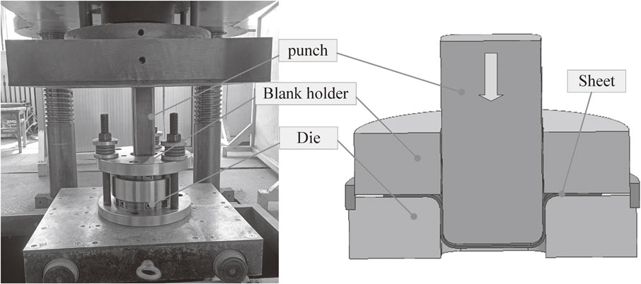
Test equipment.

The dimensions of the dies and sheet.
In this paper, ABAQUS software was used to simulate the deep drawing process of box parts. The material model was consistent with the material used in the drawing tests, which was 1 mm thick 08Al sheet. In the FE simulation, the Hill48 anisotropic yield criterion was adopted, the dies were set as discrete rigid body, and the metal sheet was meshed with shell elements. The shape, size and process parameters of the FE model were consistent with those of the process tests. The ABAQUS software provides a convenient interface for the establishment of the material fracture model. The two-dimensional fracture curve obtained in Fig. 7 can be directly input into the material model of the simulation software to simulate the fracture problem in the forming process.
It is known from the calculation expression of the critical fracture BHF that the friction coefficient is one of the critical parameters in the calculation process, which is difficult to solve in the theoretical solution and experimental process. In Ref. 26), the authors developed a friction measuring device during deep drawing and tested the friction coefficients of 4 kinds of steel under PE film lubrication. In this paper, the average value of 0.0828 was taken as the friction coefficient between the sheet and dies under the condition of PE film lubrication.
For the parameters shown in Fig. 9, the theoretical calculation of the critical fracture BHF of 1 mm thick 08Al sheet was carried out, and the critical fracture BHF curve was obtained. At the same time, the forming fracture behavior was simulated coupling with MMC ductile fracture criterion in the range of 20–80 kN BHF, followed by box-shaped parts drawing tests. Define the shrinkage rate of the outer edge in the flange area λ = (R0 − Rw)/R0, recording the shrinkage rate at the moment of fracture under a constant BHF, the results of theoretical calculations, numerical simulations and process experiments are shown in Fig. 10.

The critical fracture BHF curve.
According to Fig. 10, it can be seen that the critical fracture BHF gradually decreases with the increase of the flange shrinkage rate, and a similar trend is obtained in both theoretical calculations, numerical simulations and experiments. In the theoretical calculation, when the flange shrinkage rate is 0.19, the critical fracture BHF is the smallest, which is 33 kN. After that, the radial tensile stress in the flange area tends to slow down, so the critical fracture BHF obtained by theoretical calculation will increase. In contrast, the constant BHF control was adopted in the deep drawing tests and FE simulation, and the ultimate BHF after the safety point was unable to be judged. In the FE simulation, no fracture occurred when the BHF was 20 kN and 25 kN, while the fracture occurred due to severe wrinkling when the BHF was 15 kN. During the tests, no fracture occurred below a BHF of 40 kN, except for a severe wrinkling at a BHF of 15 kN, which led to fracture. The results demonstrate that the theoretical calculation and FE simulation of the minimum critical fracture BHF are both lower than the experimental value, in which the error of the theoretical calculation of the minimum critical BHF is 17.5%, and the theoretical calculation is closer to the experimental value than the FE simulation. In addition, until the minimum ultimate BHF appears, the ultimate BHF obtained from both numerical simulations and theoretical calculations is less than the experimental value. This is mainly because the thickness change was ignored in the process of mechanical analysis, while there is a thinning process before fracture in the actual forming process. In the numerical simulation, the fracture curve was constructed assuming unidirectional loading and plane stress, which leads to errors with the actual. Furthermore, the strength coefficient and hardening index of the material are key parameters in the process of theoretical calculation and fracture curve construction, and the accuracy of the mechanical property parameters has an influential effect on the forming prediction.
The authors would like to thank the laboratory staff of Yanshan university for their great help and suggestions in the process experiments.