Abstract
The effects of grain size on the hydrogen embrittlement susceptibility of pure Ni and Ni–20Cr alloy were investigated. The hydrogen embrittlement susceptibility was evaluated through tensile testing under electrochemical hydrogen charging. Relative elongation, defined as the elongation under hydrogen charging divided by elongation in air, increased with increasing grain size in pure Ni (the grain size was in the range of 11–22 µm). In contrast, the relative elongation of the Ni–20Cr alloy increased with decreasing grain size from 13 to 1.8 µm. Correspondingly, the intergranular fracture was suppressed by grain coarsening in pure Ni and grain refinement in the Ni–20Cr alloy. In addition, the intergranular fracture surface in pure Ni exhibited curved slip lines and that in the Ni–20Cr alloy exhibited straight line marks. These fractographic features imply that the mechanisms of the hydrogen-assisted intergranular crack growth in pure Ni and Ni–20Cr alloy were different, which could be attributed to the difference in their stacking fault energies.
This Paper was Originally Published in Japanese in J. Japan Inst. Met. Mater. 85 (2021) 49–58.
1. Introduction
Currently, hydrogen energy is regarded as an effective resource for reducing environmental load. However, in utilizing the resource, hydrogen embrittlement has been considered as a problem when metal structural members are exposed to hydrogen environment. Therefore, there has been a high demand for developing hydrogen-resistant materials for hydrogen-energy-related infrastructure. To develop hydrogen-resistant materials, thermodynamically-stable face-centered cubic (FCC) alloys have been given importance owing to their low susceptibility to hydrogen embrittlement. Conventional Fe–Cr–Ni alloys, such as SUS316L and SUS310S, which have mechanically stable FCC phase at room temperature, show superior resistance to hydrogen embrittlement.1) For instance, when evaluated through tensile testing with 45 MPa hydrogen gas, SUS316L and SUS310S showed nearly 100% relative reduction in area (RRA), which is defined as a reduction in area with hydrogen charging divided by reduction in area without hydrogen charging.1) Moreover, in the case of Fe-based alloys without a second phase, hydrogen embrittlement susceptibility increases due to decreases in thermal and mechanical stabilities of the FCC phase against the body-centered cubic (BCC) phase.2) Therefore, alloy composition-based prediction of hydrogen embrittlement susceptibility has been proposed in terms of Ni equivalent1,3) and Md304) criteria, which indicate the composition dependence of FCC phase stability against BCC phase. The phase stability-based prediction successfully describes the hydrogen embrittlement susceptibility of various Fe-based alloys, including SCM435 and SUS304.
However, some alloys with Ni equivalent of over 40% show less than 100% RRA, even though the FCC phase is stable. For example, intergranular fracture of pure Ni has been reported, although it has a stable FCC structure.5–7) Fe–Mn-based twinning-induced plasticity (TWIP) steel8,9) and CoCrFeMnNi high-entropy alloy,10,11) which have been recently noted as high-strength high-ductility FCC alloys, also show intergranular fracture and reduction of ductility due to hydrogen embrittlement. This indicates that to develop hydrogen-resistant stable FCC alloys, such as Ni, Fe–Mn, and high-entropy alloys, additional significant factors affecting hydrogen embrittlement susceptibility other than FCC phase stability, which has been discussed for Fe–Cr–Ni systems, must be considered.
In this study, we focused on the intergranular fracture that occurs when hydrogen embrittlement occurs in stable FCC alloys. In this context, hydrogen-enhanced decohesion (HEDE),12,13) hydrogen-enhanced localized plasticity,14,15) and hydrogen-enhanced strain-induced vacancy16,17) have been suggested as mechanisms of hydrogen-related intergranular fractures. Based on these theories, the important factors are the grain boundary strength, dislocation slip locality, and local vacancy density. Therefore, it is essential to consider how the microstructural factors affect the grain strength and grain stress concentration to consider the hydrogen embrittlement mechanism. Moreover, when considering the chemical composition dependence of hydrogen embrittlement susceptibility, we must understand the effects of solute alloying elements and hydrogen on the three microstructural factors. In particular, when hydrogen embrittlement in high-alloy systems is comparatively investigated with pure metals in many studies including this one, the effects of high-concentration solute alloying atoms are primarily important. Although the mechanisms of microstructural stress concentration are dependent on the alloying system, stacking fault energy (SFE) is the main factor in FCC alloys with a fully solid solution state. The lower the SFE, the more the cross slip is suspended, which assists the dislocation pile-up on the grain boundary. Therefore, the dislocation pile-up increases the stress on the grain boundary, which acts as the driving force for intergranular fracture. Hydrogen decreases the SFE of FCC alloys;18,19) however, the effect of hydrogen, which drastically alters the difference in the SFE between different metals with similar degree of hydrogen content, has not been reported. Furthermore, as a reduction in SFE increases the local vacancy density,20) the SFE criterion for estimating the chemical-composition dependence of hydrogen embrittlement susceptibility can consider the effect of hydrogen-enhanced vacancy generation as the factor assisting the intergranular fracture due to stress concentration at grain boundaries. In the case of Ni–Cr–Fe alloy, it has been reported that hydrogen embrittlement susceptibility is higher at lower SFE.21) However, according to the abovementioned criterion, the SFE (chemical composition) dependence is simply regarded as a problem of stress concentration at grain boundaries due to dislocation pile-up. If the hydrogen embrittlement susceptibility of thermodynamically stable FCC alloys in a complete solid solution state is considered with the above-mentioned criterion, there would be exceptional cases that are not explained by SFE. The exceptional portion is interpreted in terms of grain boundary strength, which is the other primary factor that determines the chemical composition dependence of hydrogen embrittlement susceptibility.
Actually, in the case of as-solution-treated materials that do not contain any second phases, the hydrogen embrittlement behavior of stable FCC alloys is explained in terms of grain boundary strength and stress concentration at grain boundaries. One example is the hydrogen embrittlement behavior of Ni alloys, such as Ni–Cr binary and Ni–Cr–Fe ternary alloys in which Fe has been used for commercial Ni-based alloy.21,22) Replacing Fe with Ni increases the hydrogen embrittlement susceptibility of Ni–Cr–(Fe) alloys monotonically. However, the effect of stress concentration at grain boundaries decreases with an increase in Ni content due to an increase in SFE.22) Therefore, hydrogen embrittlement susceptibility cannot be explained by stress concentration at grain boundaries, and the decrease in grain boundary strength is considered as a detrimental factor for embrittlement behavior. However, when Ni is replaced with Cr, the dependence of hydrogen embrittlement susceptibility of Ni–Cr alloys on the Cr content is not monotonic. The hydrogen embrittlement susceptibility increases with increasing Cr content up to 20 mass%, and decreases when the Cr content is higher than 20 mass%.2,23) Note that the addition of Cr reduces the SFE in Ni–Cr–(Fe) alloys even when the Cr content is higher than 20 mass%.21) Namely, the decrease in the hydrogen embrittlement susceptibility with increasing Cr content higher than 20 mass% could not be explained by the stress concentration at the grain boundaries. This indicates that increasing the amount of Cr (or decreasing the amount of Ni) reinforces the grain boundary strength when Ni is replaced with Cr. The increase in hydrogen embrittlement susceptibility by the addition of 20 mass% Cr indicates that the main factor for the increase in hydrogen embrittlement susceptibility is the stress concentration at the grain boundaries due to the reduction of SFE, and not the decrease in grain boundaries strength. In other words, the complexity of the dependence of hydrogen embrittlement susceptibility on Cr content is attributed to the competitive effect of variations in grain boundary strength and SFE. In particular, the addition of Cr up to approximately 20 mass%, which has a large effect on SFE, increases hydrogen embrittlement susceptibility, whereas the addition of Cr at concentration higher than 20 mass% decreases the hydrogen embrittlement susceptibility due to the increase in grain boundary strength. It is difficult to validate these hypotheses based on direct evidence; however, we consider that the hypotheses can be indirectly validated through a comparative study on the grain size dependence of hydrogen embrittlement susceptibility in Ni–Cr alloys. Specifically, we expected that grain refinement treatment, which reduces the grain boundary stress concentration stemming from dislocation pile-up,24,25) would be effective in suppressing hydrogen embrittlement in Ni–20Cr alloys that exhibit low SFE.
In this study, we assumed that the hydrogen embrittlement behaviors of pure Ni and Ni–20Cr alloys are mainly dependent on the grain boundary strength and stress concentration at the grain boundaries. Based on this assumption, the grain size dependence of the hydrogen embrittlement susceptibility of the two alloys, in which different controlling factors dominate the susceptibility to embrittlement, were comparatively analyzed. Comparative analysis is believed to demonstrate a general classification of intergranular fractures in FCC alloys in terms of the primary influential factors. Here, we present a mechanism-orientated guideline for the effective use of grain refinement treatment and chemical composition design for the development of hydrogen-resistant materials.
2. Experimental Procedure
2.1 Materials
Commercially-available pure Ni (JIS H4552) and Ni–20Cr alloy were used. The Ni–20Cr alloy used in this study was produced by melting. The chemical compositions are listed in Table 1. These ingots were hot-forged at 1100°C to a thickness of 60 mm, width of 120 mm, and length of 200 mm. Subsequently, they were hot-rolled at 1100°C to a thickness of 20 mm, width of 150 mm, and length of 480 mm. The rolled bars were solution-treated at 1100°C for 1 h and then water-quenched. The heat-treated bars were further rolled at room temperature to reduce the thickness by 93%. The rolled plates were cut though spark machining. The specimens were annealed for recrystallization at 700°C, 800°C, and 900°C for 15 min in pure Ni and at 700°C and 800°C for 15 min and 900°C for 30 min in Ni–20Cr. All the specimens were oil-quenched after annealing.

Table 1 Chemical compositions of the pure Ni and Fe–20Cr alloy (mass%).
To observe the microstructure after recrystallization, the specimens were mechanically polished using waterproof abrasive papers, 9 and 3 µm diamond slurries, and colloidal silica with a particle size of 60 nm. The microstructure was observed using scanning electron microscopy (SEM) at an acceleration voltage of 15 kV. The average grain sizes were measured using an intercept method based on the SEM images.
2.3 Tensile tests and fractographic observation
The tensile specimens were ground mechanically and electropolished to obtain stress-relieving and slick surfaces. Figure 1 shows the shape of the specimen used in tensile tests. The tensile tests were performed at a strain rate of 1 × 10⁻⁴ s−1 up to rupture at room temperature. As shown in Fig. 2, hydrogen was introduced with a cathodic charge during the tensile tests. Hydrogen charging was conducted at a current density of 10 A m−2 in an aqueous solution of 3 mass% NaCl, and was initiated immediately after the start of the tensile test. After tensile testing, the specimens were cleaned with acetone, and the fracture surface was observed using SEM at an acceleration voltage of 15 kV. The strains were measured using a video extensometer. For the tensile test under cathodic hydrogen charging, strains were calculated from the crosshead displacement, based on a regression equation obtained using an approximation curve (second polynomial function) for the relationship between strain-crosshead displacement in air.

3. Results
3.1 Initial microstructure
Figure 3 shows the BSE images after recrystallization heat treatment. The average grain sizes measured using the BSE images are listed in Table 2. The grain size increased with increasing heat-treatment temperature. These grain sizes included annealed twin boundaries, and the annealed twin boundary density was higher in the Ni–20Cr alloy than in pure Ni. In addition, the grain size of pure Ni was larger than that of the Ni–20Cr alloy, irrespective of the heat treatment conditions.

Table 2 Average grain sizes of the pure Ni and Cr–20Ni alloy with different annealing temperatures. The average grain sizes include annealing twin boundaries.
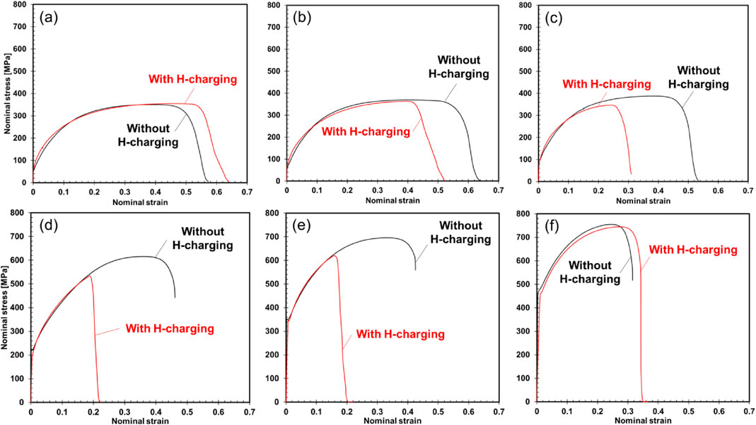
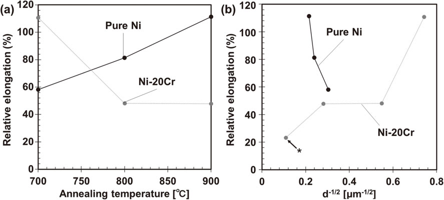
Figure 4 shows the stress-strain curves obtained from the tensile tests in air. The yield strength and tensile strength of both the pure Ni and Ni–20Cr alloy increased due to grain refinement (Figs. 4(a) and (b)). The 0.2% proof stress calculated from these curves was approximately proportional to the −1/2 power of the grain sizes, indicating that the increase in strength agreed with the Hall-Petch relation (Fig. 4(c)). Figure 5 shows the change in the stress-strain curve due to hydrogen charging. For pure Ni, the effect of hydrogen charging decreased as the grain size “increased” (Figs. 5(a)–(c)). When the specimens were heat-treated at 900°C, a decrease in elongation due to hydrogen charging did not occur (Fig. 5(a)). On the contrary, for the Ni–20Cr alloy, the degree of hydrogen-induced elongation degradation decreased as the grain size “decreased” (Figs. 5(d)–(f)), and no decrease in elongation due to hydrogen was observed in the 700°C heat-treated specimens (Fig. 5(f)). These trends were summarized in terms of relative elongation (the elongation of the hydrogen-charged specimen divided by the elongation obtained from the test in air), as shown in Fig. 6. For pure Ni, the relative elongation increased with increasing heat treatment temperature (Fig. 6(a)), that is, with increasing grain size (Fig. 6(b)). For the Ni–20Cr alloy, the opposite grain-size dependence of the relative elongation was observed. Figure 7 shows the true stress-strain curves and work-hardening rate curves of the pure Ni and Ni–20Cr alloy. The elongation at the fracture point was higher than the true strain at which the work-hardening rate was equal to the corresponding true stress obtained from the tests in air (Figs. 7(a) and (c)). Hence, the fracture occurred after satisfying the Considère criterion (necking condition).
| \begin{equation}
\frac{d \sigma}{d \varepsilon} \leq \sigma,
\end{equation}
| (1) |
where σ and ε indicate the true stress and true strain, respectively. As the true stress after necking could not be determined without measuring the actual width and thickness of the specimen during the test, the true stress-strain curves after satisfying the Considère criterion are not shown in
Fig. 7; however, it can be seen in
Fig. 5 that deformation continued after necking. On the contrary, in the tests under hydrogen charging (
Figs. 7(b) and (d)), except for the test conditions in which elongation did not decrease (900°C heat-treated pure Ni specimens and 700°C heat-treated Ni–20Cr specimens), a rapid decrease in the work-hardening rate and premature fracture occurred before the Considère criterion was satisfied.
3.3 Observation of fracture surface
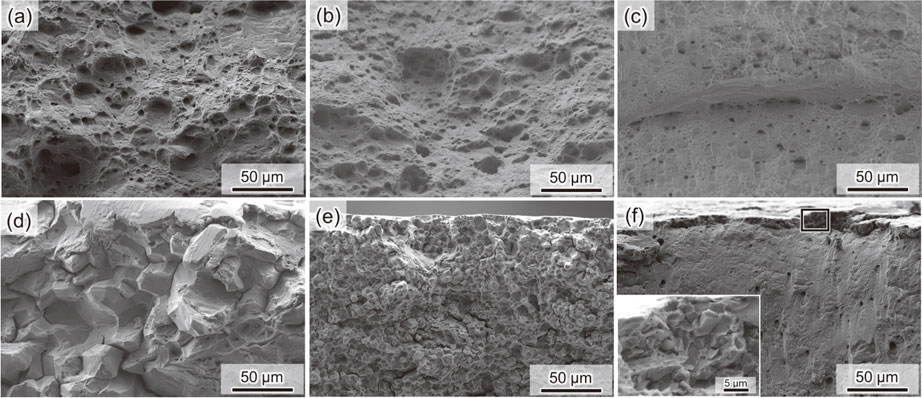
Figure 8 shows a fracture surface of pure Ni. All specimens tested in air exhibited necking and subsequent ductile fractures (Figs. 8(a)–(c)). On the contrary, all of the hydrogen-charged specimens, including the 900°C heat-treated Ni specimen that did not show elongation degradation, exhibited brittle-like fracture surfaces (Figs. 8(d)–(f)). Figure 9 shows magnified images of the fracture surfaces. The specimens tested in air showed dimples and shearing fracture surfaces as typical characteristics of ductile fractures (Figs. 9(a)–(c)). The intergranular and quasi-cleavage fracture surfaces were mixed in the hydrogen-charged specimens, irrespective of the heat-treatment temperature. Specifically, the feature of the quasi-cleavage fracture appeared markedly as the grain size increased. The intergranular fracture tended to be suspended as the grain size increased according to the change in the fracture surface morphology. In addition, as shown in Fig. 10, curved slip lines were frequently observed on the intergranular fracture surface of the hydrogen-charged specimen, regardless of the heat-treatment condition (grain size).
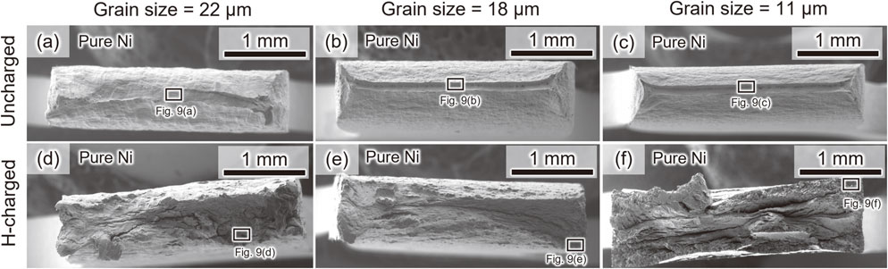

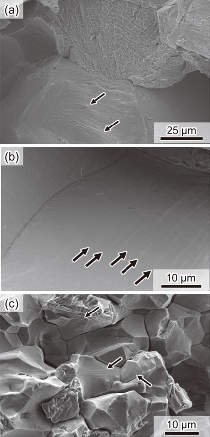
Figure 11 shows overview images of the fracture surfaces of the Ni–20Cr alloy. The specimens tested in air showed necking and subsequent ductile fractures similar to the case of pure Ni (Figs. 11(a)–(c)). When hydrogen charging was performed, brittle feature appeared on the entire region of the fracture surface of the specimen heat-treated at 900°C, the one that had the largest grain size (Fig. 11(d)). The hydrogen-charged specimen heat-treated at 800°C also showed a similar brittle fracture surface; however, the specimen heat-treated at 700°C showed ductile fracture similar to that tested in air. The magnification shown in Figs. 12(a)–(c) show that the fracture surfaces obtained from the tests conducted in air were fully covered with dimples, which indicate that typical ductile fractures occurred. When hydrogen charging was conducted, brittle features were observed on the entire regions of the fracture surfaces of the specimens heat-treated at 900°C and 800°C (Figs. 12(d), (e)). Specifically, an intergranular fracture surface was predominantly observed, and a portion of the fracture surface showed a quasi-cleavage fracture feature. Although a brittle feature was not confirmed in the overview image of the fracture surface of the 700°C-heat-treated specimen, the magnification indicates that an intergranular fracture portion was present near the surface of the specimen (edge of the fracture surface), as shown in Fig. 12(f). Additional magnified images (Figs. 13(a) and (b)) indicate that there were linear marks on the fracture surfaces. Although curved slip lines were also observed similar to those observed in pure Ni, the linear marks were observed only in the Ni–20Cr alloy.

4. Discussion
4.1 Effects of hydrogen on stress-strain curve
The pure Ni specimen with a grain size of approximately 11 µm showed degradation of elongation due to hydrogen charging. The hydrogen-induced degradation was suppressed by increasing the strain size, and the specimen with a grain size of approximately 22 µm did not show significant loss of elongation. However, even when elongation degradation did not occur, the fracture surface exhibited a brittle feature. An important result to understand the grain-size dependence is that the fraction of the intergranular fracture region on the fracture surface increased with increasing grain size. Chen et al. reported26) that crack initiation resistance is not a detrimental factor for fracture strength, and resistance to subsequent intergranular crack propagation is a noticeable factor. More specifically, quasi-cleavage cracking and subsequent final failure occurred when the intergranular crack length and/or flow stress rapidly increased in the early deformation stage. A significant area of quasi-cleavage fracture surface was observed in the specimen with a grain size of 22 µm, which implies that the growth rates of the intergranular cracks were low, and the quasi-cleavage fracture occurred via loading of a high stress after necking of the specimen. In Section 4.2, we discuss the intergranular crack growth behavior in pure Ni under the influence of hydrogen, and the grain-size dependence of hydrogen embrittlement behavior in terms of flow stress variation.
The Ni–20Cr alloy also exhibited elongation degradation due to hydrogen charging. However, in contrast to pure Ni, the hydrogen embrittlement susceptibility in the Ni–20Cr alloy decreased with decreasing grain size. When significant elongation degradation due to hydrogen was confirmed, the entire region of the fracture surface was covered with intergranular fracture features. In contrast, the specimen with a grain size of 1.8 µm, in which the mechanical degradation was completely suppressed, showed a ductile fracture surface with numerous dimples as a major feature. A noticeable observation in the results is that a thin layer with a thickness corresponding to a size of a few grains was observed near the edge of the fracture surface. This indicates that intergranular crack initiation occurred irrespective of the grain size. This implies that an increase in the resistance to intergranular crack propagation due to grain refinement suppressed the elongation degradation. The suppression of hydrogen embrittlement by grain refinement has been reported in austenitic steels with low SFEs, and the reduction in stress concentration at grain boundaries has been considered as a significant factor.25,27–29) In Section 4.3, the suppression mechanism of hydrogen-assisted crack propagation by grain refinement is discussed in terms of dislocation pile-up at the grain boundaries.
4.2 Effect of grain size on crack growth in pure Ni
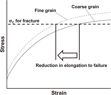
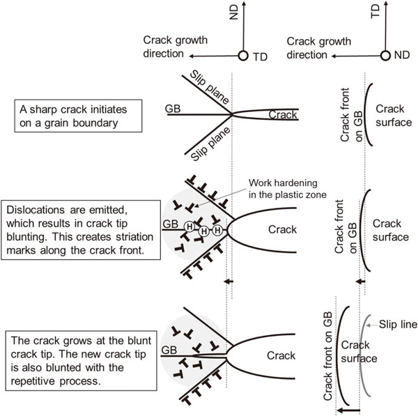
As an important fact to discuss the crack propagation in pure Ni, we here note the curved slip lines shown in Fig. 10. Figure 14 shows schematics for models of crack propagation within a grain, which is assumed in this study. As shown in the upper row, the crack tip immediately after the crack initiation is sharp. When the crack initiation process is completed, the crack front shape becomes curved to reach a mechanically equivalent shape in which the mechanical load at the crack tip front becomes homogeneous.30) As plastic deformation can be activated in pure Ni even under the influence of hydrogen, crack tip blunting occurs via dislocation emission after crack initiation (middle row of Fig. 14). The dislocation emission from the crack tip slightly moves the crack tip position, and the process provides surface relieves (slip lines) on the crack surface. Crack tip blunting causes strain hardening and enables the loading of a large stress. Furthermore, the stress gradient at the crack tip induces hydrogen accumulation,31,32) which reduces the grain boundary strength. When the local stress at the crack tip becomes higher than the grain boundary strength, the crack propagates further (lower row of Fig. 14). The repetition of the crack tip plasticity evolution and crack growth results in numerous curved slip lines on the fracture surface. Assuming the above-mentioned crack growth process, the crucial factors are the strain hardening in the plastic zone, hydrogen accumulation near the crack tip, and remote stress. Considering the effects of grain size on these three factors, the hydrogen embrittlement behavior of pure Ni observed in this study could be interpreted. As shown in Fig. 7(a), the variation in the grain size did not affect the strain hardening behavior of pure Ni. Although the hydrogen accumulation behavior was dependent on both the yield strength and strain hardening rate that affected the stress gradient at the crack tip, the effect of yield strength on an identical strain was also small when the strain level was high. This indicates that the effect of grain size did not significantly affect the hydrogen accumulation behavior from a mechanical viewpoint. The remote stress, which was the third factor, corresponded to the flow stress in the tensile tests. As shown in Fig. 4(a), the flow stress increased with decreasing grain size. As a result, the strain required to reach the critical stress for the fracture decreased, as schematically shown in Fig. 15. This indicates that in terms of remote stress the hydrogen-assisted intergranular crack growth occurred earlier when the grain size was decreased. Therefore, the hydrogen embrittlement susceptibility of pure Ni increased with decreasing grain size.
Next, we discuss the hydrogen-assisted crack growth of the Ni–20Cr alloy based on the linear marks on the fracture surface shown in Fig. 13. As the SFE of a Ni–20Cr alloy is lower than that of pure Ni,21) many dislocations piles up on a specific crystallographic plane against the grain boundaries, which increases the local stress acting on the grain boundaries (left in Fig. 16). The stress concentration region, where hydrogen can localize, act as the intergranular crack initiation site (middle of Fig. 16). As the dislocations are emitted at the tip of a small crack that was formed in front of the main crack, the dislocation-driven crack tip blunting results in linear marks on the crack surface, as seen in the fractographic observation. The reasons for the linear shape of the slip lines, unlike in pure Ni, are as follows:
(1) Small cracks formed along the line of intersection of the dislocation array and the grain boundary. Therefore, the front shape of the small crack was linear.
(2) As the length of the small cracks is shorter than that of the main crack, the distance of the movement of the crack tip during crack opening was small. The small crack then coalesced with the main crack, which resulted in the propagation of the main crack (right image of Fig. 16). Based on this mechanism, the primary factor for the hydrogen embrittlement of the Ni–20Cr alloy was the stress concentration at the grain boundaries that resulted from the low SFE. As mentioned in Section 4.1, hydrogen-assisted intergranular fracture in FCC alloys with an SFE has been reported to be suppressed by reducing the stress concentration at the grain boundaries. In the Ni–20Cr alloy, the reduction in stress concentration at the grain boundary owing to grain refinement could suppress the hydrogen-assisted intergranular fracture and associated degradation of elongation. In addition, in terms of crack growth, grain refinement has been reported to assist the stress shielding effect stemming from the elastic stress field of dislocations and grain boundaries.33–35) As the lattice-defect-driven stress shielding effect became significant when the grain size was decreased to a few µm or sub-µm, the difference in the minimum grain size between the pure Ni and Ni–20Cr alloy would also be important to discuss the details of the difference in the hydrogen embrittlement behaviors of the two alloys.
5. Conclusions
In this study, we investigated the hydrogen embrittlement behavior of FCC alloys in the context of grain boundary strength and stress concentration at grain boundaries, using pure Ni and Ni–20Cr alloy. More specifically, pure Ni and Ni–20Cr alloy specimens with different grain sizes were prepared to evaluate the grain size dependence of hydrogen embrittlement susceptibility. Then, based on the effects of grain size, the relationship between the plastic deformation behavior and intergranular crack growth is discussed. A summary is presented below.
-
(1)
The hydrogen embrittlement susceptibility of pure Ni decreased with increasing grain size. In contrast, the hydrogen embrittlement susceptibility of the Ni–20Cr alloy decreased with decreasing grain size.
-
(2)
The grain coarsening in pure Ni suppressed the intergranular fracture, and a quasi-cleavage fracture feature appeared on the fracture surface.
-
(3)
The grain refinement in the Ni–20Cr alloy suppressed the intergranular fracture, and ductile fracture features, such as dimples, appeared on the fracture surface.
-
(4)
The fracture surface of the hydrogen-charged pure Ni specimen exhibited curved slip lines, which can be explained in terms of the mechanically-equivalent shape of the crack front. On the contrary, the fracture surface of the hydrogen-charged Ni–20Cr alloy specimen exhibited linear and curved slip marks. These observations indicates that the growth mechanism of the hydrogen-assisted intergranular crack of pure Ni was different from that of the Ni–20Cr alloy.
The results of this study, coupled with conventional knowledge of microstructure-related intergranular fracture, indicate that the reduction in flow stress due to grain coarsening the decreased the hydrogen embrittlement susceptibility of pure Ni. That is, in the present experimental condition, the critical stress for the intergranular fracture was mainly determined by the macroscopic mechanical condition, rather than the dislocation-driven stress concentration near the grain boundaries. On the contrary, the dislocation-driven stress concentration was the primary factor that caused the intergranular fracture in the Ni–20Cr alloy, which had a lower SFE than that of pure Ni. Therefore, the reduction in stress concentration at the grain boundaries due to grain refinement significantly suppressed the intergranular fracture, which resulted in a decrease in hydrogen embrittlement susceptibility. Specifically, the degree of stress concentration associated with dislocation increased with decreasing SFE owing to the low frequency of cross slip, which intrinsically increased the susceptibility of intergranular fracture. Thus, the grain refinement in the Ni–20Cr alloy reduced the dislocation-driven stress concentration near the grain boundaries and the associated hydrogen embrittlement susceptibility.
Acknowledgements
This work was financially supported by JSPS KAKENHI (JP16H06365 and JP20H02457) and the Japan Science and Technology Agency (JST) (Grant no. 20100113) under the Industry-Academia Collaborative R&D Program.
REFERENCES
- 1) T. Omura, J. Nakamura, H. Hirata, K. Jotoku, M. Ueyama, T. Osuki and M. Terunuma: ISIJ Int. 56 (2016) 405–412. doi:10.2355/isijinternational.ISIJINT-2015-268
- 2) M. Koyama, C.C. Tasan and K. Tsuzaki: Eng. Fract. Mech. 214 (2019) 123–133. doi:10.1016/j.engfracmech.2019.03.049
- 3) L. Zhang, M. Wen, M. Imade, S. Fukuyama and K. Yokogawa: Acta Mater. 56 (2008) 3414–3421. doi:10.1016/j.actamat.2008.03.022
- 4) C. Izawa, S. Wagner, M. Deutges, M. Martín, S. Weber, R. Pargeter, T. Michler, H.-H. Uchida, R. Gemma and A. Pundt: Int. J. Hydrogen Energ. 44 (2019) 25064–25075. doi:10.1016/j.ijhydene.2019.07.179
- 5) D.H. Lassila and H.K. Birnbaum: Acta Metall. 35 (1987) 1815–1822. doi:10.1016/0001-6160(87)90127-1
- 6) M.L. Martin, B.P. Somerday, R.O. Ritchie, P. Sofronis and I.M. Robertson: Acta Mater. 60 (2012) 2739–2745. doi:10.1016/j.actamat.2012.01.040
- 7) K. Wada, J. Yamabe, Y. Ogawa, O. Takakuwa, T. Iijima and H. Matsunaga: Mater. Sci. Eng. A 766 (2019) 138349. doi:10.1016/j.msea.2019.138349
- 8) Y.S. Chun, K.-T. Park and C.S. Lee: Scr. Mater. 66 (2012) 960–965. doi:10.1016/j.scriptamat.2012.02.038
- 9) M. Koyama, E. Akiyama, Y.-K. Lee, D. Raabe and K. Tsuzaki: Int. J. Hydrogen Energ. 42 (2017) 12706–12723. doi:10.1016/j.ijhydene.2017.02.214
- 10) K.E. Nygren, K.M. Bertsch, S. Wang, H. Bei, A. Nagao and I.M. Robertson: Curr. Opin. Solid State Mater. Sci. 22 (2018) 1–7. doi:10.1016/j.cossms.2017.11.002
- 11) K. Ichii, M. Koyama, C.C. Tasan and K. Tsuzaki: Scr. Mater. 150 (2018) 74–77. doi:10.1016/j.scriptamat.2018.03.003
- 12) R.A. Oriani and P.H. Josephic: Acta Metall. 25 (1977) 979–988. doi:10.1016/0001-6160(77)90126-2
- 13) M. Yamaguchi, K. Ebihara, M. Itakura, T. Kadoyoshi, T. Suzudo and H. Kaburaki: Metall. Mater. Trans. A 42 (2011) 330–339. doi:10.1007/s11661-010-0380-6
- 14) I.M. Robertson, P. Sofronis, A. Nagao, M.L. Martin, S. Wang, D.W. Gross and K.E. Nygren: Metall. Mater. Trans. B 46 (2015) 1085–1103. doi:10.1007/s11663-015-0325-y
- 15) M.L. Martin, M. Dadfarnia, A. Nagao, S. Wang and P. Sofronis: Acta Mater. 165 (2019) 734–750. doi:10.1016/j.actamat.2018.12.014
- 16) M. Nagumo: Mater. Sci. Technol. 20 (2004) 940–950. doi:10.1179/026708304225019687
- 17) M. Nagumo and K. Takai: Acta Mater. 165 (2019) 722–733. doi:10.1016/j.actamat.2018.12.013
- 18) A.E. Pontini and J.D. Hermida: Scr. Mater. 37 (1997) 1831–1837. doi:10.1016/S1359-6462(97)00332-1
- 19) P.J. Ferreira, I.M. Robertson and H.K. Birnbaum: Mater. Sci. Forum 207–209 (1996) 93–96. doi:10.4028/www.scientific.net/MSF.207-209.93
- 20) M. Hatano, M. Fujinami, K. Arai, H. Fujii and M. Nagumo: Acta Mater. 67 (2014) 342–353. doi:10.1016/j.actamat.2013.12.039
- 21) D.M. Symons: Metall. Mater. Trans. A 28 (1997) 655–663. doi:10.1007/s11661-997-0051-4
- 22) K. Kawano: Technical Report Nippon Steel Sumitomo Metal Corp. 114 (2017) 53–60.
- 23) K. Tomatsu, K. Miyata and T. Omura: ISIJ Int. 56 (2016) 418–423. doi:10.2355/isijinternational.ISIJINT-2015-289
- 24) T. Onomoto, Y. Terazawa, T. Tsuchiyama and S. Takaki: ISIJ Int. 49 (2009) 1246–1252. doi:10.2355/isijinternational.49.1246
- 25) Y. Bai, Y. Momotani, M.C. Chen, A. Shibata and N. Tsuji: Mater. Sci. Eng. A 651 (2016) 935–944. doi:10.1016/j.msea.2015.11.017
- 26) T. Chen, M. Koyama, S. Hamada and H. Noguchi: Theor. Appl. Fract. Mech. 107 (2020) 102556. doi:10.1016/j.tafmec.2020.102556
- 27) I.-J. Park, S.-M. Lee, H.-H. Jeon and Y.-K. Lee: Corros. Sci. 93 (2015) 63–69. doi:10.1016/j.corsci.2015.01.012
- 28) N. Zan, H. Ding, X. Guo, Z. Tang and W. Bleck: Int. J. Hydrogen Energ. 40 (2015) 10687–10696. doi:10.1016/j.ijhydene.2015.06.112
- 29) M. Koyama, K. Ichii and K. Tsuzaki: Int. J. Hydrogen Energ. 44 (2019) 17163–17167. doi:10.1016/j.ijhydene.2019.04.280
- 30) M. Aibara, M. Koyama, S. Hamada and H. Noguchi: Procedia Structural Integrity 13 (2018) 1148–1153. doi:10.1016/j.prostr.2018.12.239
- 31) P. Sofronis and R.M. McMeeking: J. Mechan. Phys. Solids 37 (1989) 317–350. doi:10.1016/0022-5096(89)90002-1
- 32) D. Sasaki, M. Koyama, K. Higashida, K. Tsuzaki and H. Noguchi: Int. J. Hydrogen Energ. 40 (2015) 9825–9837. doi:10.1016/j.ijhydene.2015.05.187
- 33) M. Tanaka, N. Fujimoto and K. Higashida: Mater. Trans. 49 (2008) 58–63. doi:10.2320/matertrans.ME200711
- 34) M. Tanaka, K. Higashida, T. Shimokawa and T. Morikawa: Mater. Trans. 50 (2009) 56–63. doi:10.2320/matertrans.MD200817
- 35) T. Shimokawa, M. Tanaka, K. Kinoshita and K. Higashida: Phys. Rev. B 83 (2011) 214113. doi:10.1103/PhysRevB.83.214113