Mechanics of Materials
Suppression of Springback for Longitudinally Curved Part by Imparting In-Plane Compression Stress in Press Forming
2022 年 63 巻 3 号 p. 304-310
詳細
2022 年 63 巻 3 号 p. 304-310
Dimensional accuracy defects caused by springback behavior are one of the serious problems in press forming for automobile parts using ultrahigh-strength steel sheets. In particular, in hat-shaped parts curved in the longitudinal direction, camber back, which is a kind of springback behavior, occurs. In this study, in order to suppress camber back, a new press-forming method that can impart in-plane compression stress was investigated using parts with a simple hat-shaped section and a W-shaped section simulating automotive parts. As a result, it was found that the amount of camber back decreases on applying compression stress in the longitudinal direction, because the bending moment caused by the difference between stress in the punch bottom area and that in the flange area was reduced. It was also clarified that the sensitivity of the amount of camber back to tensile strength was lowered when this forming method was used. Furthermore, a forming method in which buckling in both ends under a high compression condition can be prevented was developed.
This Paper was Originally Published in Japanese in J. JSTP 60 (2019) 161–166.

Fig. 7 Relationship between compression rate and amount of camber back.
The demands in recent developments of automobiles are weight reduction of the body to reduce CO2 emission and improved crashworthiness to meet severe collision safety standards. As one solution to meet these demands, the application of ultrahigh-tensile-strength steel sheets (UHSS) of over 980 MPa is increasing, mainly in skeleton parts. In general, many automotive parts are manufactured by cold press forming, which has the advantage of excellent productivity. However, as material strength increases, not only reduced press formability due to cracks and wrinkles, but also dimensional-accuracy defects attributable to an enhanced springback becomes problematic. Particularly in the case of dimension accuracy defects, it is necessary to consider the improvement of robustness of dimension against variations of material properties and forming conditions in mass production, that is, the reduction of dimensional-accuracy variation.
As a technique to ensure dimensional accuracy in mass production, springback compensation by die shape modification has been applied to date. Although the time required for die shape corrections can be reduced by springback analysis by the finite element method (FEM), many die modifications are still required when press forming UHSS since springback is very large.1,2) In addition, improved robustness by die compensation cannot be expected because little improvement is realized in terms of the occurrence of stress at the bottom dead center, which is a factor in springback. To reduce the amount of springback and improve robustness, it is important to reduce the stress at the bottom dead center, and in particular, to reduce the bending moment.
The types of representative dimension accuracy defect attributable to springback are roughly divided into springback of longitudinal curvature, torsion, and cross-sectional springback,3) and many countermeasure techniques have been proposed for each from the viewpoint of stress reduction at the bottom dead center. Hiramoto et al. conducted a factor analysis to identify a driving stress of springback for a front pillar reinforcement with torsion. On the basis of the results of the analysis, they proposed the countermeasure of adding a concave shape to the area where the driving stress occurs.4) For reducing the amount of cross-sectional springback, reduction of the residual bending moment by bending with tension or compression is effective. Nakata and Hirose reported a technique in which a step bead is formed by sliding the movable die via a cam mechanism in the end stage of forming, whereby the angle change and wall warpage are reduced through the effect of tension generated in the vertical wall, that is, stretch bending.5) Momodori and Mita devised a die structure that can apply compression to the vertical wall of a hat shape and showed that the amount of wall opening can be greatly reduced through the effect of compressive bending.6)
Long components warped in the longitudinal direction, represented by a roof-cross or a front side member, display a type of springback (hereinafter, camber back) in which the longitudinal curvature becomes small, and as the longitudinal curvature radius of the component decreases, shape freezing in mass production becomes difficult. Sato et al. examined a rear member model and showed that twisting and camber back could be improved by adopting a proper bead layout at the flange portion, e.g., a small-width form and a large-width form.7) However, there are very few reports on techniques to reduce the amount of camber back that occurs in parts with a small longitudinal curvature.
In this study, the effect of adding longitudinal compression on the amount of camber back and the robustness of dimensional-accuracy against material strength was investigated by FEM using long components with a basic hat-shaped cross section and a W-shaped cross section similar to that of an actual automotive component. An investigation using hat-shaped cross-sectional parts clarified the fact that camber back and robustness were greatly improved by applying compressive stress. We also confirmed that camber back is reduced in the samples with W-shaped cross sections simulating actual parts, demonstrating that the application of compressive stress is effective.
Figures 1 and 2 show the whole shape and cross-sectional shape of the hat-shaped part used in the FEM analysis, respectively. The part has a constant cross-sectional shape and a constant curvature in the longitudinal direction. The punch bottom is located on the outer side of the bend of the longitudinal curvature, and the flange is located on inner side of the bend. The curvature radius at the flange position is 780 mm, and the cross-sectional shape is 137 mm in width and 20 mm in height.

Dimensions of part with simple hat-shaped section.

Dimensions of simple hat-shaped section.
A press forming simulation and springback analysis by FEM were carried out using parts with the shapes described above. Table 1 shows the mechanical properties of the materials used in the FEM analysis. The materials were cold-rolled steel sheets, and Japanese Industrial Standards (JIS) No. 5 test pieces taken from the perpendicular direction of rolling were used in the tensile tests.

Figure 3 shows the analytical model used for the forming simulation. Figure 3(a) shows a typical stamping model without the application of compressive stress in the longitudinal direction (hereinafter, conventional forming), and Fig. 3(b) shows a model with in-plane compression (hereinafter, compression forming). The die model for conventional forming was composed of upper and lower dies, and the blank was a rectangle with the dimensions of 835 mm × 180 mm. On the die for compression forming, walls parallel to the press direction were designed at both sides of the punch in order to prevent longitudinal displacement of blank ends during press forming. Compressive stress was generated in the forming blank by using a blank longer than the arc length (835 mm) along the curvature of the punch bottom of the product. Blank lengths of 838.9 mm and 851.5 mm were used, and the generated compressive strain was 0.46% and 1.98 mm, respectively.

Forming simulation models.
As shown in Fig. 3(b), forming simulation was carried out using a warped blank. The curvature was determined such that the longitudinal length of the warped blank was equal to the product length. The radius of curvature was varied from 700 mm to 790 mm. No FEM analyses of the warped blanks were conducted, because the warped deformation was elastic and thus the influence on hat-shape forming was thought to be small.
Using LS-DYNA ver. 971 as the solver, we performed the forming simulation by the dynamic explicit method and the springback analysis by the static implicit method. Since stress reversal occurs in compression forming, the Yoshida-Uemori (Y-U) model8) was used, because this model can express the Bauschinger effect. Tension–compression tests with a strain range of ±3% were conducted for each material to identify the parameters of the Y-U model. The mesh size of the blank was 2 mm and the friction coefficient was 0.12. The springback analysis was performed with five fully constrained nodes in the middle of the part. Figure 4 shows the evaluation method of the amount of camber back. The amount of displacement in the press direction at the center of the width of both ends of the formed part was defined as the amount of springback. The effect of in-plane compression on camber back was investigated using the 1180 MPa tensile strength material. The dependence of the amount of camber back on the material strength was investigated by comparing conventional forming with compression forming under a 1.58% compressive strain condition using 590 MPa to 1180 MPa materials.

Evaluation method of springback behavior.
Figure 5 shows the part with a W-shaped cross section simulating a roof-cross, which is an automobile frame part. The length is 1000 mm, the radius of the curvature of the flange position is 4000 mm, and the cross-sectional shape is 221 mm in width and 15 mm in height. Considering the symmetrical shape of this part, FEM analysis was performed on a 1/4-size model. Unlike the hat-shaped part, the flange is located outside the longitudinal curvature and the punch bottom is located inside.

Dimensions of part with W-shaped section simulating roof cross.
The FEM analysis conditions were the same as those given in the previous section. The forming simulation was carried out by conventional forming and in-plane compression forming. The conventional forming tools consisted of an upper die and a lower die, as shown in Fig. 3(a), and the blank was a rectangle (1/4-size model) with a length of 502 mm and a width of 123 mm. In-plane compression forming was performed by two different forming methods. In one, the same forming tools as those for the model shown in Fig. 3(b) were used, and compressive stress was applied in the longitudinal direction by constraining both ends of the blank by means of the walls. The compressive strain was changed from 0.12 to 0.97% by changing the blank length, and the blank was set under the warped condition as described in the previous section. No FEM analysis was performed for curving of the blank. As will be mentioned later, this forming method tends to cause buckling at the end of the product. Therefore, to prevent buckling, the structure of the upper die was designed to form the two ends in advance by dividing 100 mm from both them, as shown in Fig. 6. The blank has the same shape as that in conventional forming. Figure 6 also shows the forming process. As shown in (2) in the figure, the two 100 mm ends were formed with die 2 at the beginning of forming. Subsequently, the center part became the bottom dead center when forming using die 1 under the condition that both ends were constrained.

Forming behavior of in-plane compression forming.
Figure 7 shows the relationship between the compressive strain and the amount of camber back for the 1180 MPa steel. The compressive strain of 0% means conventional forming. The amount of camber back was 13.1 mm at the compressive strain of 0%. As the compressive strain increased, the amount of camber back was greatly reduced, reaching 2.5 mm at the compressive strain of 1.98%. However, the reduction effect tended to decrease when the compressive strain exceeded 1.58%.

Relationship between compression rate and amount of camber back.
Figure 8 shows the longitudinal stress distribution at the center of thickness at the bottom dead center for the 1180 MPa material at the compressive strains of 0%, 0.74%, 1.58% and 1.98%. At the compressive strain of 0%, tensile stress occurred at the punch bottom located outside the longitudinal curvature, and compressive stress was generated at the flange located inside the curvature. The mechanism of camber back is considered to be the bending moment caused by this stress difference. The tensile stress of the punch bottom was reduced by applying in-plane compressive stress. Figure 9 shows the relationship between compressive strain and longitudinal stress. Since the stress in the range of 150 mm from both ends is not uniform owing to buckling during in-plane compression forming, the average values in the regions, excluding 150 mm from the two ends, were used for the stress values on the vertical axis. As can be seen in Fig. 9, the longitudinal stress of the punch bottom was +500 MPa at the compressive strain of 0%, it but decreased as the compressive strain increased. The stress was reversed to compressive stress from the compressive strain of about 0.9% and was stable at about −500 MPa above the compressive strain of 1.58%. On the other hand, the longitudinal stress of the flange was about −1100 MPa at the compressive strain of 0% and was almost unchanged regardless of the compressive strain. Because compressive strain was introduced in the flange portion, which is a compressive deformation area, the change in stress due to the addition of in-plane compression was considered to be small. As can be understood from the behavior of longitudinal stress, camber back improved because the stress difference between the punch bottom and the flange decreased as the compressive strain increased. As shown in Fig. 8, buckling at both ends of the punch bottom occurred easily in this in-plane compression forming analysis. When the compressive strain exceeded 1.58%, the longitudinal stress of the punch bottom did not decrease below −500 MPa because compressive deformation was concentrated in the buckling area; as a result, the improvement of camber back was small.

Longitudinal stress distribution at middle thickness at bottom dead point in various compression rates.

Relationship between compression rate and longitudinal stress at middle thickness of bottom dead point.
Next, the sensitivity of camber back to material strength is described. As mentioned in the previous section, in in-plane compression forming, camber back is improved by decreasing tensile stress, which is a cause of bending moment, to compressive stress. Since the bending moment is reduced, the sensitivity to material strength is also expected to improve. Figure 10 shows the relationship between the tensile strength and the amount of camber back in conventional forming and in-plane compression forming. Here, the compressive strain in in-plane compression forming is 1.58%. Although the amount of camber back increased with increasing material strength with both forming methods, the slope of that increase was substantially smaller in in-plane compression forming than in conventional forming, confirming that the sensitivity to material strength was greatly improved. In the evaluation in which camber back increased per 100 MPa increase in material strength, the amount of camber back increased by about 1.2 mm in conventional forming but decreased to about 0.2 mm in in-plane compression forming. Thus, an improvement effect of about 83% was recognized.

Relationship between tensile strength and amount of camber back.
Figure 11 shows the relationship between tensile strength and the longitudinal stress at the center of the thickness at bottom dead center at the compressive strain of 1.58% in order to consider the sensitivity improvement effect. The stress values on the vertical axis were the same as those in Fig. 9, except in the vicinity of 150 mm from the two ends. At this compressive strain, buckling occurred in the region about 150 mm from the two ends in all materials. The longitudinal stress in the flange region showed almost the same compressive stress in conventional forming and in-plane compression forming, and compressive stress increased with increasing material strength. On the other hand, the longitudinal stress in the punch bottom region showed tensile stress in conventional forming and compressive stress in in-plane compression forming, both of which gradually increased with increasing material strength. In comparison with the stress difference between the punch bottom and the flange, which is the factor of bending moment causing camber back, the sensitivity of camber back to material strength is less in in-plane compression forming. Therefore, the sensitivity of camber back to material strength is improved.

Relationship between tensile strength and longitudinal stress at middle thickness of bottom dead point.
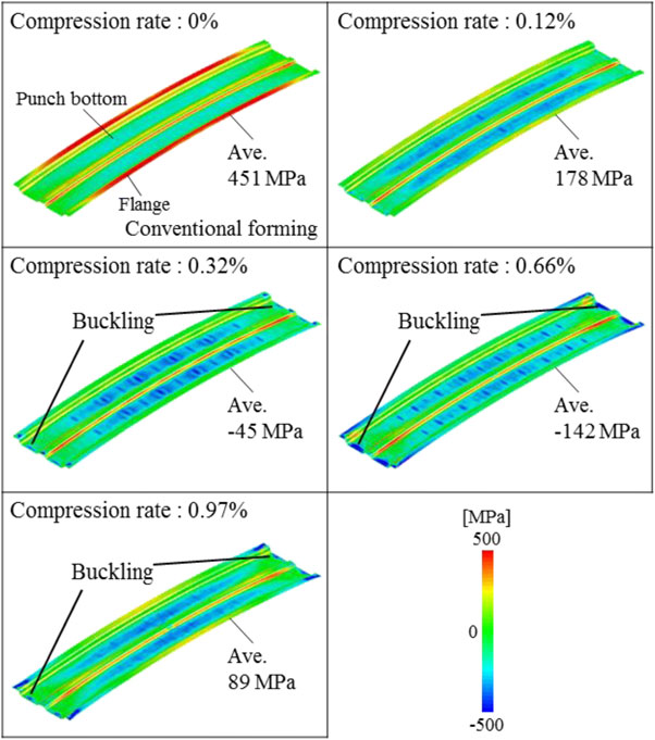
Figure 12 shows the relationship between the compressive strain and the amount of camber back in in-plane compression forming in which both ends are constrained by walls, as shown in Fig. 6(1). The amount of camber back was 17.7 mm at the compressive strain of 0%, i.e., conventional forming. Camber back decreased to 8.4 mm when the compressive strain was increased to 0.66%, but then increased to 12.6 mm at the compressive strain of 0.97%. Figure 13 shows the longitudinal stress distribution at the center of thickness under various compressive strains. At the compressive strain of 0%, tensile stress was generated in the flange positioned outside the curvature, and compressive stress was generated in the punch bottom positioned inside the curvature. Then, tensile stress in the flange was reduced by applying in-plane compression. Buckling was observed at both ends when the compressive strain exceeded 0.32%. Figure 14 shows the relationship between the compressive strain and the longitudinal stress at the center of thickness. As in Fig. 9, the average stress of the area excluding 150 mm from both ends was used to remove the effect of buckling. The tensile stress in the flange observed in conventional forming decreased as the compressive strain increased. Tensile stress changed to compressive stress at the compressive strain of 0.32% and its value was minimum at the compressive strain of 0.66%. On the other hand, the compressive stress in the punch bottom did not change significantly regardless of the compressive strain. The longitudinal stress difference between the flange and the punch bottom, which is a cause of camber back, is minimized at a compressive strain of 0.66%, which corresponds to the result for the amount of camber back in Fig. 12. Then, at a compressive strain over 0.66%, compressive deformation was concentrated in the buckling area; as a result, the longitudinal stress difference no longer decreased. Thus, the improvement of camber back become small.

Relationship between compression rate and amount of camber back.
Longitudinal stress distribution at middle thickness of bottom dead point under various compression rates.

Relationship between compression rate and longitudinal stress at middle thickness of bottom dead point.
As described above, in the forming method in which both ends are constrained by walls, buckling occurs because of the low compressive strain, and there is concern that the die may be damaged if the buckling collapses at the bottom dead center. Also, wear damage of the wall area is a concern in mass production because the wall and the blank edge are in contact under high surface pressure. Therefore, in order to prevent the buckling at the two ends, another in-plane compression forming step, in which the region 100 mm from each end was formed in advance by using the blank holder, was investigated, as shown in Fig. 6.
Figure 15 shows the deformation state when preforming of the two ends is completed. In comparison with the die shape, flexure of the material is observed at the longitudinal center, and a compressive strain of about 0.8% is generated when the center part is formed. Figure 16 shows the longitudinal stress distribution at bottom dead center in conventional forming and in-plane compression forming of the 1180 MPa material. Here, conventional forming is the same as that in Fig. 13. In in-plane compression forming, compressive stress occurred in the flexure region, as shown in Fig. 15, and no buckling was observed. These results confirmed that it is possible to prevent buckling and to apply compressive stress by forming the two ends in advance.

Deformation state after forming of the two ends.

Longitudinal stress distribution at middle thickness of bottom dead point.
Figure 17 shows the relationship between the tensile strength and the amount of camber back in the preforming-type in-plane compression forming described above and in conventional forming. The amount of camber back was measured in the same way as shown in Fig. 4, and the amount of displacement in the press direction was measured at the center of the cross section of the two ends of the formed product. The effect of applying in-plane compression to the flange area greatly reduced the amount of camber back in in-plane compression forming, and an improvement of about 9.0 mm was confirmed in the 1180 MPa material. The sensitivity of camber back to material strength was also improved. The increase in the amount of camber back per 100 MPa increase in tensile strength was about 1.6 mm in conventional forming and about 1.0 mm in in-plane compression forming, showing an improvement effect of about 37% in the case of compression forming.

Relationship between tensile strength and amount of camber back.
The improvement of camber back in longitudinally warped long parts with hat-shaped and W-shaped cross sections through the application of in-plane compressive deformation in the longitudinal direction during press forming was investigated by FEM analysis. The conclusions are as follows.