1. Introduction
Since Manabe and Wetherald1) first quantitatively demonstrated the relationship between atmospheric CO2 concentration and the increase in global surface temperature through simulation analysis in 1967, interest in international approaches to climate change has been steadily increasing. In 1997, the Kyoto Protocol, which set targets for the reduction of greenhouse gas emissions, was adopted, and at the UN Summit in 2015, the 2030 Agenda, which includes the Sustainable Development Goals (SDGs), was adopted. Japan and other countries around the world are focusing on global environmental issues.
Due to the need to reduce the environmental load, manufacturers of automotive parts and electronic devices are attempting to reduce the energy loss of the entire product assembly through compact and lightweight designs, and to save energy by improving the power density of electronic devices using a next-generation power semiconductor such as GaN. However, light alloys such as Al alloy and Mg alloy, which are often used for lightweight design, have low hardness and lack of wear resistance. Also, it is difficult to maintain a sufficient lubrication environment during operation for precision sliding parts used in automotive applications. Therefore, it is important to improve the performance and development of a surface treatment for those light alloys including surface modification that can exhibit excellent wear resistance even if under non-lubrication.2) In addition, in electronic devices, it is desirable to develop technology to prevent degradation of bonding reliability of mounted components due to increased heat density caused by higher power density and higher operating frequency. Thus, many researches have been actively conducted to improve the performance of electronic materials used in packaging, such as solder and sealing materials, and to develop new bonding methods for semiconductors.3) The surface treatment of the electrode, which forms the interface with the bonding material such as solder, is also an important technical element to improve the bonding reliability. Thus, there is a need to further improvement of the performance of electroless Ni plating, multi-layer plating including a Ni layer, and alloy plating, which are currently used for those applications.
Then, we propose the method of compositing cellulose nano-fiber (CNF) obtained from plants, which is a renewable resource, to Ni plating to improve that performances. CNF is a nanoscale material with 1/5 times higher density and 5 times higher strength than steel materials, and has been industrially applied in various fields such as resin composite materials.4) It has been reported that Ni composite plating, regardless of the plating method whether electro or electroless, has high hardness by compositing with hard particles such as ceramics or silicon carbide, and has self-lubricating property by compositing with resinous materials such as polytetrafluoroethylene (PTFE), that improves the wear resistance.5) Therefore, Ni composite plating has been used for applications such as press molds and sliding parts of automobiles, however there are few reports of composite plating codeposited organic materials such as cellulose6) and there are no reports using CNF. CNF has the characteristics of high strength and crystalline resin, thus it is expected to show high wear resistance when it is composited with Ni plating film. Furthermore, CNF has extremely low linear expansion coefficient (1/50 times of glass4)) and high chemical stability.7) Thus, when Ni-CNF composite plating is applied to surface treatment of the electrode, it is expected to be effective in reducing thermal stress at the solder joint and inhibiting the formation of brittle intermetallic compound (IMC) at the solder/electrode interface, which degrades the joint reliability.
Therefore, in this study, fabrication of Ni-CNF plating film was attempted by electroplating method. The purpose of this study was set to investigate the deposition conditions, observe the film morphology and clarify the codeposition mechanism in fabricated Ni-CNF plating film.
2. Experimental Procedure
2.1 Sample materials
To simplify the consideration of plating reaction, stainless steel (SUS304H) which material components are not easily eluted in the plating solution was used as the plated material. The chemical composition of SUS304H is shown in Table 1. The size of SUS304H was set to 10 × 10 × 0.5 mm (plating reaction area; 220 mm2) and degreased by ultrasonic cleaning with acetone as a pretreatment. Used thin plates of SUS304H were commercially available product (CIRAS0.5-200-200, MISUMI Group Inc.), which is cold-rolled plate without any heat treatment, surface treatment or surface finishing, and prepared by cutting to the set size.

Table 1 Chemical composition of SUS304H.
Ni plating without CNF suspended was conducted to compare with the Ni-CNF composite plating film. As the plating solution, Watts bath solution which composition is shown in Table 2 was used, and the plating bath was A-53-M2-P01W manufactured by YAMAMOTO-MS Co., Ltd. The solution volume and temperature were set at 500 mL and 50°C, respectively. The bath was constantly aerated at a flow rate of 1.5 L/min. The anode was a pure Ni plate and the cathode i.e. the plated material was SUS304H. The distance between the electrodes was set at 50 mm. Current density (C. D.) was set at 2.5 A/dm2, and current charge density (C. C. D.), which is C. D. multiplied by plating time, was set at 3000 C/dm2. The immersion time of specimens in the plating solution was a few minutes longer than the plating time (i.e., C. C. D. divided by C. D.) in order to prepare for the plating experiment. After plating process, specimens were washed with pure water.
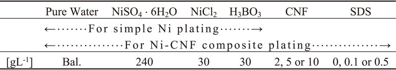
Table 2 Chemical composition of plating solution.
CNF (nanoforest-S manufactured by Chuetsu pulp & paper Co. Ltd.) which is slurry form bamboo pulp, with 1.7 mass% CNF content, and contains fibers with a diameter of over 100 nm, was suspended to the Watts bath solution.
Hereinafter, CNF amount means not slurry form weight but CNF net weight. Also, in some conditions, sodium dodecyl sulfate (SDS) was added to the solution as a wetting agent. The Watts bath solution with CNF and SDS (or no SDS) added, which composition is shown in Table 2, was used for Ni-CNF composite plating. C. D. and C. C. D. were set at 2.5, 5 or 10 A/dm2, and 300, 3000, 9000 or 18000 C/dm2, respectively. Other plating conditions and process were the same as the Ni plating without CNF suspended described above.
2.3 Analyzing process
2.3.1 Observation of film surface
Surfaces of obtained Ni and Ni-CNF film were observed by an electron probe micro analyzer (EPMA, EPMA-1610, Shimadzu Corp.) at acceleration voltage of 15 kV.
2.3.2 Observation of cross-section of film
Cross-sectional samples were prepared by following procedure to observe and element mapping analysis. Obtained Ni-CNF film was embedded in epoxy resin, and cut to expose cross-section of the film. Cross-section was polished by emery papers step by step up to #4000 (European FEPA) and coated by an osmium plasma coater (HPC-1SW, Shinku device Co. Ltd.). Observation of backscattered electron (BSE) image and element mapping analysis of the cross-section of the film were conducted by EPMA at acceleration voltage of 15 kV. Thickness of film was measured from BSE images using the software, ImageJ 1.53e.8)
2.3.3 Quantification analysis
Quantification of CNF in obtained Ni-CNF film was conducted by X-ray fluorescence (XRF) analysis (EA1200VX, Hitachi high-tech Corp.) with the fundamental parameter (FP) method. The method is reported for a use of quantification of cellulose contained in plants with standard samples.9)
Prepared standard samples were the mixed powder of Ni and dried CNF whose weight ratio of Ni:CNF is 100:0, 95:5, 90:10 and 50:50. Quantified film specimens were fabricated at 18000 C/dm2 to be more than 60 µm thickness which is sufficiently over XRF maximum measurable thickness for the Ni film,10) and avoids the effect of Ni in the substrate material SUS304H. XRF analysis was conducted under the air atmosphere, and acceleration voltage, X-ray tube current and measuring time were set at 15 kV, 1000 µA and 100 sec, respectively. However, due to the specifications of the equipment, detected CNF is defined to be the amount of CNF derived carbon (C) converted to CNF equivalent.
2.3.4 Vickers hardness testing
Vickers hardness (HV) test was conducted to the surfaces of Ni and Ni-CNF film fabricated at 3000 C/dm2 using a micro HV tester (MVK-H1, Akashi Corp.). In order to ensure that the measured HV is not affected by the substrate;11) SUS304H, loading was set at 25 gf (0.245 N) to make the indentation depth approximately 1/5 times of the thickness of the film. In this study, the thickness of the film was approximately 10 µm at 3000 C/dm2. In addition, HV of plated Ni-CNF film was at least 300 HV which was almost reported HV value of electrodeposited Ni plated under the conditions similar to those in this study.12)
3. Results and Discussions
3.1 Results of surface observation
BSE and secondary electron (SE) images of surfaces of Ni-CNF composite plating are shown in Fig. 1, where the black area in BSE image is CNF and the gray area is Ni. It seems that the large diameter cellulose fibers are exposed on the surface and incorporated into electrodeposited Ni. The mottled areas around the large-diameter fibers in both BSE and SE images seems to be codeposited with relatively small-diameter fibers or CNF aggregation.

Figure 2 shows SE images of electrodeposited Ni grains in Ni-CNF and Ni films. Ni grains deposited from Ni-CNF composite plating are finer than those deposited from Ni plating. It is known that the grain size of the electroplated film is affected by several factors such as C. D., thickness of film (which is almost the same meaning as C. C. D. in this study), agitation conditions, plating temperature and substrate conditions.13) However, in this case, CNF, which is an impurity from the viewpoint of Ni plating bath, was added to the bath, therefore, it is considered to be one of the causes that the electrical energy consumed in Ni electrodeposition process tended to the nucleation side rather than the nuclear growth side.14) In the surface of film, significant difference caused by the addition of SDS was scarcely observed.
3.2 Results of cross-section observation and analysis
3.2.1 Morphology and element mapping analysis
BSE image and element mapping analysis results of the cross section of Ni-CNF composite plating film, which is fabricated at 3000 C/dm2 and 2.5 A/dm2 by 10 g/L CNF suspended solution without SDS, are shown in Fig. 3. As shown in the BSE image of Fig. 3(a), the obtained cross section of the plating film had double layer structure parallel to the plating surface. As a result of mapping analysis, C derived from CNF was detected in the layer on the substrate side (Fig. 3(b)), and the layer on the surface side consisted almost exclusively of electrodeposited Ni (Fig. 3(d)). C detected on the surface side of the Ni layer was derived from epoxy resin. The former and the latter layers are hereinafter referred to as the CNF-rich layer and the surface side electrodeposited (SSED) Ni layer. In the case of no SDS or 0.1 g/L SDS addition, similar double layer structure was formed in other plating conditions in this study. On the other hand, significant growth of the CNF-rich layer was clearly observed under the condition of 0.5 g/L SDS addition.

Figure 4 shows BSE image and element mapping analysis results of Ni-CNF composite plating film fabricated at 3000 C/dm2 and 2.5 A/dm2 by 10 g/L CNF suspended solution, and with 0.5 g/L SDS. CNF was incorporated into the CNF rich layer in aggregated form (Fig. 4(b)), and Fe was detected in the CNF-rich layer, surrounding the CNF aggregation (Fig. 4(c)). Ni was only partially detected in the CNF-rich layer (Fig. 4(d)). The SSED Ni layer was also consisted almost exclusively of Ni.
3.2.2 Thickness of film
The relationship between C. C. D., thickness of film and CNF-rich layer, in the film fabricated at different C. D. with 10 g/L CNF suspended solution without SDS, is shown in Fig. 5. Hereafter, the error bars shown in the graphs in the figures represent standard deviations. The total thickness was linearly increased with an increase in C. C. D., while the thickness of the CNF-rich layer tended to increase very slightly. This indicates that the growth of the total thickness is dominated by the growth of the SSED Ni layer after the formation of the CNF-rich layer.
The relationship between CNF concentration in the plating solution, thickness of film and CNF-rich layer, in the film fabricated at 18000 C/dm2 and 10 A/dm2 without SDS, is shown in Fig. 6. No significant difference in the thickness of the CNF-rich layer was observed with an increase in the CNF concentration in the solution.
Furthermore, the relationship between SDS addition to the plating solution, thickness of film and CNF-rich layer, in the film fabricated at 3000 C/dm2 and 2.5 A/dm2 by 10 g/L CNF suspended solution, is shown in Fig. 7. As described above, a significant increase of the thickness in CNF-rich layer was observed under the conditions of SDS 0.5 g/L addition, while since the difference between the total thickness and the thickness of the CNF-rich layer is almost the same, it seems that the thickness of the SSED Ni layer is scarcely affected by SDS.
3.3 Results of quantification analysis
Figure 8 shows the results of the XRF quantification for the plating film. The concentration of CNF in the plating solution did not correlate with the CNF content in the plated film (hereafter referred to as CNF codeposition rate) under the experimental conditions in this study, and the rate ranged from 6.5 to 8.5 mass%. The effect of SDS addition on the CNF codeposition rate was also not observed. However, since the XRF quantitative analysis is performed on the surface of the plating film, the actual CNF codeposition rate may not be accurately represented because the detection depth of the characteristic X-ray is almost constant. The thickness of the SSED Ni layer, which is the layer on the surface side of the plating film for the XRF analysis, is approximately constant at approximately 10 µm, i.e., even if the thickness of the CNF-rich layer which strongly affects the CNF codeposition rate changes, the XRF quantitative analysis is not able to detect all the areas in the thickness direction of the CNF-rich layer since the detection depth of characteristic X-rays in the CNF-rich layer from the surface side does not change. In this study, as mentioned above, XRF quantitative analysis is performed on the surface of the specimen without resin filling. Although it was not able to distinguish CNF derived carbon from epoxy resin derived carbon in the elemental mapping results of C in the cross sections shown in Figs. 3 and 4, the fact that CNF was able to be detected by XRF quantitative analysis indicates that the C detected in the CNF-rich layer by elemental mapping analysis is highly likely derived from CNF.

Figure 9 shows the change in HV of the film fabricated at 3000 C/dm2 and 2.5 A/dm2 with the addition of CNF and with the addition of both CNF and SDS. Except for the Ni plating, the amount of CNF suspended in the plating solution was 10 g/L, and the addition of SDS was 0 or 0.5 g/L. Figure 10 shows the surface of the film around the indentation of HV testing, and the film is fabricated at 3000 C/dm2 and 2.5 A/dm2 with 10 g/L CNF suspended solution without SDS. HV testing was conducted to the surface of the film avoiding the large diameter cellulose fibers as shown in Fig. 1. The HV of the electrodeposited Ni film was 291 HV, which was almost the same as the value reported in previous study,12) while the addition of CNF improved the HV by about 30% to 402 HV. When both CNF and SDS were added, the hardness was 426 HV, which showed almost no change compared with that of Ni-CNF composite plating film. Since the codeposition of CNF on the film surface was observed in the surface observation, it is assumed that the HV increase in the Ni-CNF composite plating film obtained in this study is due to the effect of CNF codeposited on the surface. On the other hand, since no homogeneous CNF codeposition was observed in the cross-sectional observation of the films, this phenomenon is considered to be limited to the film surface only.

In the CNF-rich layer which contains a large amount of CNF, as shown in Figs. 3 and 4, more Fe derived from the substrate than Ni was detected together with C derived from CNF. Therefore, it is considered that CNF was not incorporated into the plating film in the process of Ni reduction and deposition, rather it was formed by physical incorporation of CNF into the space inside the substrate caused by some factors. In addition, in the growth process of the SSED Ni layer, it is considered that CNF was not incorporated into the SSED Ni layer due to electrostatic repulsion between negatively charged CNF in the plating solution and the substrate as a cathode as one of the factors. Therefore, we are considering the following steps for the codeposition mechanism of Ni-CNF composite plating film. The schematic model of the codeposition mechanism is shown in Fig. 11.

(I) At the stage before starting plating, when the substrate SUS304H is immersed in the plating solution, the passive film of chromium oxide on the surface of the substrate becomes unstable due to chloride ions in the plating solution, and pitting corrosion occurs on the surface of the substrate even if only slightly. This is similar to the corrosion of stainless steel by seawater, which contains chloride ions.15) At the same time, the concentration of CNF in the plating solution increases near the surface of the substrate due to intermolecular forces or physical adsorption. At this time, CNF is negatively charged in the plating solution due to hydrogen ion desorption from the carboxyl group of CNF.
(II) With the start of current loading, the cathode, i.e. the surface of the substrate, becomes a reducing atmosphere due to the generation of hydrogen gas, and the passive film begins to be locally destroyed. In other words, the process of cathodic electrolytic cleaning,16) which is generally performed for the purpose of removing oxides and degreasing the plated material as a pre-treatment for plating, is being performed at the same time. At this stage, the corrosion reaction of the substrate by chloride ions is suppressed, however, hydrogen gas is also generated from the inside of the pitting corrosion that has already occurred, and the peeling force caused by the mechanical action induces cracks or peeling inside the substrate in the area where tensile residual stress is loaded in the low depth near the surface inside the substrate. The substrate material SUS304H used in this study is a cold-rolled material, and it is known that tensile stress is residual on the surface of such cold-rolled materials.17) There have been several reports on the corrosion behavior of cold-rolled SUS304, which has a slightly different composition from SUS304H. It is known that the higher the degree of rolling, the higher the crack growth rate of stress corrosion cracking18) and the lower the pitting potential, which leads to increase in pitting corrosion.19) In this study, it is possible that combined corrosion including pitting corrosion and stress corrosion cracking was promoted in the area of tensile residual stress loading, and at the same time, internal delamination near the surface of the substrate material was induced by the physical delamination effect of hydrogen gas, i.e., the cathodic electrolytic cleaning effect.
(III) CNF which existed in the near region of the cathode surface before current loading is physically trapped in such a delaminated area of the substrate. Alternatively, some of CNF is physically fixed by the reductive deposition of Ni ions. Ni deposition starts after the start of current loading, however, Ni ions are not supplied from the bulk solution sufficiently in time in these delaminated inner regions of the substrate, and continuous Ni deposition does not occur. The CNF-rich layer is formed at this stage.
(IV) On the surface side of the substrate, Ni ions are transferred by concentration gradient and electrophoresis, resulting in continuous Ni deposition. On the other hand, since CNF is negatively charged, electrostatic repulsion occurs between the cathode substrate and CNF, causing CNF to migrate to the anode side. This is one factor that results in the formation of the SSED Ni layer, which contains very little CNF.
(V) Since then, there is no continuous codeposition of CNF in the plating film except for accidental physical trapping by contact with the surface of the substrate, i.e. the surface of the SSED Ni layer in this stage, which is carried by convection by agitation, and fixed by Ni deposition.
3.5.2 Charging behavior and codeposition inhibition factor of CNF
Although the amount of carboxyl groups depends on the treatment conditions, CNF has carboxyl groups on its surface. According to L. Fras et al., cellulose purified by alkaline boiling washing, bleaching, and demineralization of natural cellulose fibers obtained from cotton has 12.81–43.26 mmol/kg of carboxyl groups.20) The CNF used in this study was produced by the ACC method,21) whereby the suspended water of bamboo pulp purified through alkaline washing and bleaching processes is injected and collided in a high pressure chamber to refine it, and is considered to have the same degree of carboxyl groups. In the TEMPO oxidation method22) reported by T. Saito and A. Isogai, the primary hydroxyl group in cellulose fibers is converted to a carboxyl group, and a maximum amount of carboxyl group of about 1.7 mmol/g is possible to be introduced.23) Researches on the charging behavior of CNF obtained by the TEMPO oxidation method (hereinafter referred to as TEMPO-CNF) and applied research using the charging behavior have been conducted.24,25) As mentioned above, CNF used in this study has not been oxidized to introduce carboxyl groups, thus its negative charging behavior in solution is expected to be much milder than that of TEMPO-CNF. However, in the electroplating method where the plating substrate is necessarily the cathode, it is certain that the negative charging behavior of CNF prevents the codeposition of CNF during the plating process by electrostatic repulsion.
On the other hand, preliminary experiments of Ni-CNF composite plating on copper alloys by electroless plating method also did not show homogeneous codeposition of CNF in the Ni layer,26) thus, it seems that electrostatic repulsion is not the only primary factor preventing codeposition. The affinity of CNF surface functional groups to inorganic materials, i.e. substrate materials, and the conductivity that enables Ni to be deposited and fixed immediately when CNF contacts the substrate surface are considered to be important for the codeposition of CNF in the plating film. Therefore, composite plating tests using CNF with silane coupling treatment27) and electrification treatment28,29) are in progress as our future research.
3.5.3 Effect of plating conditions on formation of CNF-rich layer
Regarding the relationship between C. C. D. and the thickness of film shown in Fig. 5, the fact that the thickness of the CNF-rich layer showed a slight increasing trend against the increase in C. C. D. is considered to be due to the delamination area inside the substrate expanding as the total amount of hydrogen generation increases with the increase in C. C. D., i.e. plating time. In regard to the relationship between the CNF concentration in the plating solution and the thickness of film shown in Fig. 6, the change in the CNF concentration did not affect the thickness of the CNF-rich layer since CNF is considered not to be related to the corrosion and delamination of the substrate.
In other words, keep in mind that the thickness of the CNF-rich layer is dominated by the delaminated area inside the substrate.
About the increase of the thickness of the CNF-rich layer when SDS was added at 0.5 g/L shown in Fig. 7, it was reported by Tsuru et al.30) that hydrogen gas desorption from the cathode surface was promoted due to the decrease of surface tension in the Watts bath with SDS added. Moreover, Xu et al.31) reported that corrosion of stainless steel was suppressed in NaCl solution with SDS added. Therefore, the addition of SDS works to prevent the delamination effect caused by hydrogen gas, i.e., reduction of cavitation erosion-like effect due to decrease in surface tension,32) and to suppress corrosion caused by chloride ions, thus, it is expected to decrease the thickness of the CNF-rich layer. However, in this study, an increasing effect of the thickness of the CNF-rich layer by SDS addition was observed. It is probably due to the adsorption of SDS on the surface of the substrate and on the delaminated area caused by the excessive addition of SDS, which affected the hydrogen bubbles and substrate interaction in some way and promoted the delamination phenomenon, although the cause is not clear. Therefore, further investigation is needed.
The increase of HV on the surface of Ni-CNF composite plating film against the Ni plating film shown in Fig. 9 is considered to be caused by the composite effect of CNF fixed on the SSED Ni layer surface as described above. However, since the accidental CNF codeposition in the codeposition mechanism step (V) occurs continuously with the growth of the SSED Ni layer, there is a possibility that some CNF codeposition also occurs inside the SSED Ni layer. Nevertheless, due to the performance limitations of the observation equipment used in this study, even if CNF was codeposited inside the SSED Ni layer, it was not able to be confirmed. Alternatively, it may be possible to consider a new method to estimate the CNF codeposition rate in the SSED Ni layer based on the degree of HV increase.


