Abstract
In accordance with the EU RoHS Directive, the use of Sn–3 mass%Ag–0.5 mass%Cu lead-free solder (SAC305) has become the standard in the manufacturing of electronics. Since SAC305 contains more tin than the conventional tin-lead eutectic solder, erosion of the Fe plating frequently occurs on a hand soldering iron tip and a point soldering machine nozzle. In this study, to extend the life of the Fe plating layer, we investigated the applicability of a composite plating in which Fe is combined with the boron nitride (BN) compounds. We used BN particles as the bulk material, and boron nitride nanotubes (BNNT) as a nanomaterial, to fabricate the regarded composite materials. A solderability test and an erosion resistance test were conducted on the composite plating layer, made of both Fe-BN particles and Fe-BNNTs composites. In the solderability test, the spreading factor of SAC305 on the Fe-BN particle and on the Fe-BNNT composite platings were about the same as, or a little decreased compared to, that of the bare Fe plating. The SAC305 solder was not repelled by either composite plating. In the erosion resistance test, the Fe-BNNT composite plating performed the best, and had the lowest erosion depth. The erosion depths of the Fe-BN particle composite plating and the Fe plating ranged from about 6 to 24 times greater, respectively, than those of the Fe-BNNT composite plating layer, confirming that, in a nanomaterial BNNT-base, composite diffusion of Fe into SAC 305 can be suppressed.
1. Introduction
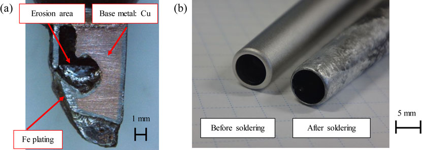
With the enforcement of the restriction of the use of certain hazardous substances (RoHS)1) directive in 2006, regarding electrical and electronic equipment, the use of lead in solder was banned. Therefore the industry changed from Sn–37 mass%Pb tin-lead eutectic solder, known as Sn37Pb, to Sn–3 mass%Ag–0.5 mass%Cu lead-free solder, known as SAC305. The latter became the main substitute. With the change to SAC305, erosion of the flow-soldering bath machine had become a problem. Previously, stainless-steel flow-soldering bath machines were used with Sn37Pb; at present, they are used with SAC305. It was quickly noticed that damage occurred to the flow-soldering baths after the changeover to SAC305.2–5) This was due to the higher Sn content in SAC305 compared to Sn37Pb. This had a higher soldering temperature due to its higher melting point of around 30 K. The mechanism of erosion in flow-soldering baths has been elucidated in previous studies, and countermeasures have been taken by treating the inner surface of the flow-soldering baths with a nitriding treatment. Another problem that has occurred with the changeover is erosion on the soldering iron tip when using a hand solder, as well as on the nozzle of a point solder machine, as shown in Fig. 1. It has been reported that adding Co or Ni to solder is effective in preventing soldering iron tip erosion.6) Erosion can be reduced by adding small amounts of Fe and other metallic elements to the solder, which is an anti-erosion measure promoted by solder manufacturers, as the concentration of Fe in the solder is increased and the melting of Fe from the solder trowel is reduced. However, if the added element exceeds the recommended amount, the composition of the SAC305 solder will change. Furthermore, if the added element is not controlled and exceeds the specified content, it will cause fluctuations in the 4Ms (Man, Machine, Method, Material). There are situations in which it is prudent to use added elements. In such situations, there is no choice but to replace them with new ones. The replacement of a hand-soldering iron tip or a point-soldering machine nozzle is costly in terms of workability, productivity, and running costs. In addition, the volume of disposed hand-soldering iron tips is expected to increase. Therefore, measures to prevent hand-soldering iron tips, erosion are becoming essential from an environmental protection standpoint. Hand-soldering iron tips and point-soldering machine nozzles need to be able to hold solder on themselves and supply molten solder to the soldering area of the electric component leads. For this reason, Fe material is generally used to provide a certain level of solder solderability to the solder. Therefore, surface treatments, such as a nitriding treatment, cannot be applied to a hand-soldering iron tip or a point-soldering machine nozzle. In our previous research, we investigated the characteristics of SAC305 by adding carbon nanotubes to Fe to improve the erosion resistance of the composite plating without changing the base Fe material. It was confirmed that the erosion resistance of SAC305 was about 100 times greater than that of Fe alone when added to inexpensive and readily available multi-walled carbon nanotubes (MWCNTs).7,8) In this study, we focused on boron nitride nanotubes (BNNTs),9–12) which have a similar structure to MWCNTs. Compared to MWCNTs, BNNTs are chemically stable and are superior in terms of oxidation and heat resistance. Their thermal conductive properties and mechanical strengths are comparable to those of carbon nanotubes.13) To verify the size effect of BNNTs, we also examined macro-BN particles for comparison. We then prepared a composite plating of Fe-BN particles and Fe-BNNTs, and evaluated the solders, solderability and erosion characteristics. To investigate the basic properties of composite plating films, high-temperature wear properties and hardness measurements were evaluated.
2. Experimental
2.1 Preparation of specimens
The evaluation samples were made by electrolytic Fe plating on a Cu plate. The composition of the plating solution is shown in Table 1. For Fe plating, we used a sulfuric acid bath to maintain a pH3 level. The BN particles were commercially available from Fujifilm Wako Pure Chemicals, and the BNNTs were synthesized at the National Institute for Materials Science (NIMS), Tsukuba. The concentration of BN particles in the plating solutions was set at 2.0 g/L, and for BNNTs it was set at 0.2 g/L. The current density was 1 A/dm2. Sodium lauryl sulfate was added as a dispersant for BN particles and BNNTs, and as an anti-pitting agent for plating. The Fe-BN particles and Fe-BNNT composite platings were analyzed by scanning electron microscopy (SEM) and a focused ion-beam scanning electron microscopy (FIB-SEM) cross-sectional analysis. X-ray diffraction (XRD) measurements were performed to evaluate the crystallinity of the composite plating. The X-ray source was Cu kα (λ = 1.54186 Å). The settings were focal spot size 1 × 10 mm, tube voltage 40 kV, tube current 15 mA, scanning axis 2θ/θ, angular range 3 to 125°. The number of test specimens for each plating was N = 1. To evaluate the roughness of the plated surface, measurements were made using a laser microscope and the arithmetic mean height (Sa) was calculated. The number of test specimens for each plating was N = 3.
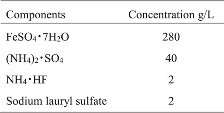
Table 1 Fe plating composition.
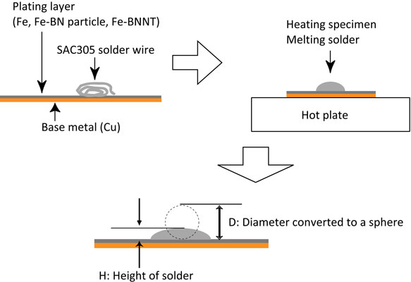
To verify the solder solderability of the Fe plating, Fe-BN particle and Fe-BNNT composite plating, their spreading factor characteristics were evaluated using a SAC305 flux-cored solder according to JIS-Z 3198-3. The test method is shown in Fig. 2. The specimens temperatures were 523 K, 573 K, and 623 K. The number of test specimens for each plating was N = 3. The three plating specimens were heated on the hotplate in the open air for 30 s. Then, the solder was cooled down to room temperature to solidify. After cooling, the height of the solid solder was measured, and the spreading factor of the solder was calculated using eqs. (1) and (2).
| \begin{equation}
S_{R} = (D-H)/D\times 100
\end{equation}
| (1) |
| \begin{equation}
D = 1.2 \times \root 3 \of V
\end{equation}
| (2) |
is the spreading factor,
D is the diameter of the theoretical solder sphere,
H is the height of the measured solder and
V is the solder volume used in the tests.
2.3 Erosion-resistance test
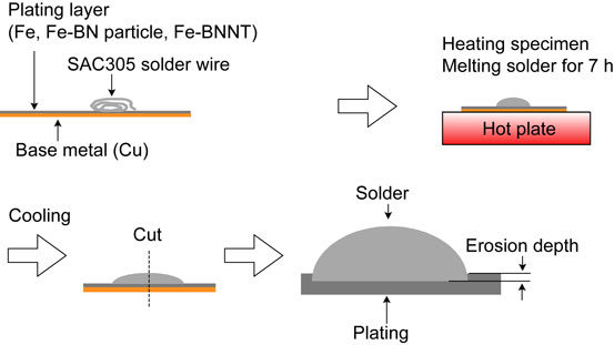
To evaluate the erosion resistance of Fe, Fe-BN particle and Fe-BNNT composite platings with molten SAC305, erosion tests were conducted. The test method is shown in Fig. 3. These plating were applied on a Cu plate with a plating thickness of 100 µm. The heating conditions were set at 573 K, 623 K, and 673 K, assuming the actual hand-solder iron tips’ temperature. After cross-sectional polishing of the sample, the erosion depth was measured with an SEM. The number of test specimens for each plating was N = 3.
2.4 Wear test
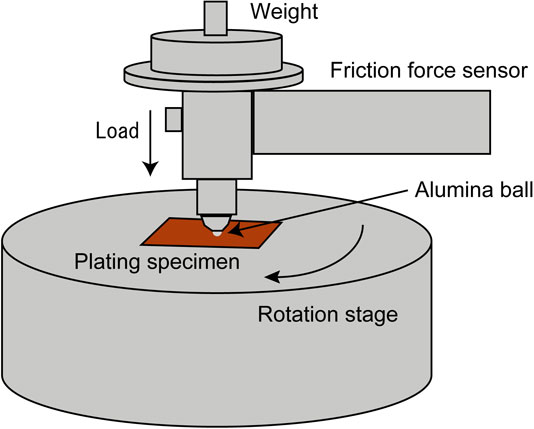
To evaluate the wear characteristics under room-temperature and high-temperature conditions, a ball-on-disk wear test was conducted to measure the coefficient of friction, wear scar diameter, and wear depth. The test method is shown in Fig. 4. For the coefficient of friction, an alumina ball was fixed to a ball holder, and the holder was fixed to a friction coefficient measurement arm. A vertical load was applied to the ball holder, and the ball holder was brought into contact with a specimen mounted on a disk. When the test started, the disk rotated and the frictional force acting between the ball and the specimen changed into a horizontal deflection of the arm. The displacement is measured by a displacement sensor, which is attached to the arm and sends data from the coefficient of friction from the vertical load and arm stiffness. The measurement of the wear scar diameter measurement was made using an SEM to measure the width of the worn area of the specimen after the wear test. For the wear depth measurements, cross-sectional analysis of the worn portion of the specimen was performed after the wear test, and the depth of wear was measured using an SEM. The temperature conditions were room temperature and 623 K. The test conditions load was set 20 N, with a rotation speed of 10 mm/s, rotation radius of 2 mm, and sliding distance of 12 m. The spherical material used was composed of alumina, with a diameter of 6 mm. The number of test specimens for each plating was N = 1.
To measure the hardness of the heated composite plating, a hardness test was carried out using nanoindentation. The test method is shown in Fig. 5. The temperature conditions were room temperature and 523 K. The test conditions were a test load of 490 mN, a load time of 10 s, a load holding time of 1 s and a load velocity of 49 mN/s. The average maximum indentation depth was 4 µm. Ten measurements were taken, and the average value was calculated. The number of test specimens for each plating was N = 1.
3. Results and Discussion
3.1 Microstructure Fe-BN particle composite plating and Fe-BNNT composite plating
The results of surface SEM analysis of Fe-BN particle and Fe-BNNT composite platings are shown in Fig. 6. Both surfaces are lumpy due to BN fractions. Many particles were found inside the plating as well as at the surface. The results of cross-sectional FIB-SEM and EDS mapping analysis of Fe-BN particle composite plating are shown in Fig. 7. The EDS shows that the material indeed contains B and N, indicating that BN materials were kept after composite fabrication. The results of cross-sectional FIB-SEM and EDS mapping analysis of Fe-BNNT composite plating are shown in Fig. 8, suggesting that BNNTs were maintained and survive in composites.


XRD patterns of the Fe plating are shown in Fig. 9. Oxides of Fe3O4 and Fe2O3 were detected in the plating after heat treatment at 623 K for 7 hours compared to the as-Fe plating. The XRD patterns of the Fe-BN particle composite plating are shown in Fig. 10. The oxides were formed by the oxidation of Fe due to heating in the open air. The diffraction peak of Fe oxide (Fe3O4) was confirmed in the plating after heating. A small diffraction peak at 2θ = 26.7° was observed. This is considered to be a BN(003) diffraction peak, since it is confirmed by Fig. 7 that BN particles are a composite in Fe plating. XRD patterns of Fe-BNNT composite plating are shown in Fig. 11. Fe(211) diffraction was detected in the as-plated specimen, while no diffraction was observed at 2θ = 26.7°; the diffraction angle was BN(003). The diffraction of Fe2O3, an oxide of Fe, was observed after heat treatment at 623 K. The oxidation of the composite plating was confirmed by heating. A small diffraction pattern of FeB(111) was observed at 2θ = 41.25°. Normally, a strong diffraction of Fe(110) appears at around 2θ = 42°, so, at 2θ = 41.25°, FeB is piled up by that diffraction and cannot be detected. However, Fe(110) was not observed in this measurement. It is thought that the combination with BNNT changed the roughness of the plated surface or the crystal structure of Fe, which is why Fe(110) diffraction was not observed.

The surface roughness measurement results are shown in Fig. 12. The surface roughness of the Fe-BN particle composite plating was about 40 times rougher than that of the Fe plating, and the surface roughness of the Fe-BNNT composite plating was about 17 times larger than that of the Fe plating. It was confirmed that the surface was roughened by the composite BN material.
3.2 Evaluation of the solderability
The results of the solder spread of molten SAC305 are shown in Fig. 13. The Fe plating has a good solderability, with a spreading factor of greater than 70% in all three temperature ranges. The Fe-BNNT composite plating also showed a good solderability of more than 70% spreading factor in all three temperature ranges, almost as good as the Fe plating. The Fe-BN particle composite plating decreased to nearly 50% at 573 K, and showed a solder spreading factor of 60% or less at 673 K. This was equivalent to Fe plating at 623 K. Generally, a rougher surface is considered to improve solderability,14) but Fig. 12 shows that the surface of Fe-BN particle composite plating is rougher than that of Fe plating, but solderability is not improved. However in our case, the solderability did not improve. Since BN is a non-metallic compound, if the entire particle is not covered with Fe in the state of being compounded with Fe, it tends to repel the solder and the solderability is reduced. In the 573 K and 673 K test pieces, it is possible that many of the BN particles taken into the plating surface were not covered with Fe and, in the 623 K test pieces, many of the BN particles were covered with Fe.

The results of a cross-sectional SEM/EDS analysis of the solderability test samples of Fe, Fe-BN particle and Fe-BNNT composite plating are shown in Fig. 14. It was confirmed that intermetallic compounds were formed at the plating-solder interface in all the samples, and that they showed solderability properties with SAC305. From the results of this study, it was confirmed that the spreading factor does not decrease significantly, even when BN particles or BNNTs are compounded with Fe, and can be applied to hand-soldering iron tips and point-solder machine nozzles.
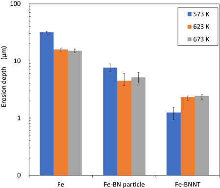
3.3 Erosion behavior
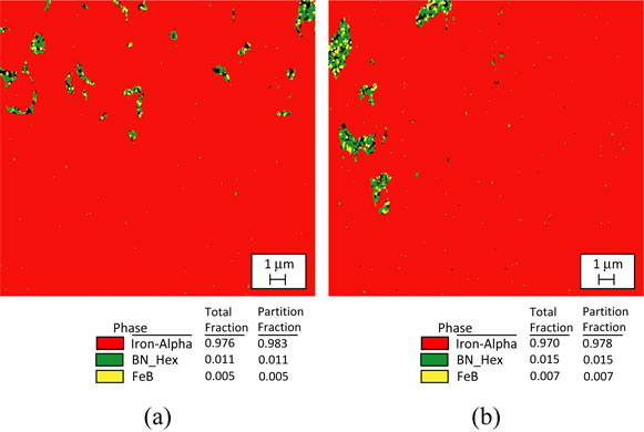
The results of the erosion test are shown in Fig. 15. It was confirmed that the erosion depth of Fe-BN particle composite plating was 2∼6 times greater than that of Fe-BNNT composite plating, and that of Fe plating was 6∼24 times greater than that of Fe-BNNT composite plating. The erosion depth of Fe-plating was 3∼4 times greater than that of Fe-BN particle composite plating, and it was confirmed that Fe-BNNT composite plating had the best erosion resistance. By combining Fe with BN particles or BNNTs, the diffusion of Fe into SAC305 could be greatly reduced. The greater inhibitive effect of Fe-BNNT composite plating on erosion by SAC305, compared to Fe-BN particle composite plating is expected to be due to the smaller size of BNNTs compared to BN particles. Since BNNT is nano-sized, it is expected that this is dispersed in the plating in a finer state than BN particles. The random presence of non-metallic BNNTs in the plating is expected to suppress the diffusion of Fe into Sn, which would involve metallic bonding. Figure 16 shows the EBSD analysis results of a Fe-BN particle composite plating, both as-plated and heat-treated at 623 K for 7 hours. In the as-plated and heat-treated composite plating specimen, an electron backscatter diffraction pattern of FeB was detected in some of the complexed BN particles. This tendency is stronger for fine particles of submicron size, and it can be seen that BN and FeB are mixed in particles with a particle size of several micron meters. In the XRD analysis (Fig. 10), the diffraction pattern of Fe diffraction peak and covered FeB(111) could not be detected, but in the composite plating specimen that was heat-treated by EBSD, FeB was also formed inside the BN particles of several micro-sizes. Figure 17 shows the EBSD analysis results of the Fe-BNNT composite plating as it was plated and after being heat-treated at 623 K for 7 hours. In the as-plating, an electron backscatter diffraction pattern of FeB was detected in a part of the complexed BNNT. It was shown that, even in the as-plating state, a part of the complexed BN will become FeB. XRD analysis (Fig. 11) shows that FeB was increased by heating, and it is expected that FeB production will proceed by heat-treating the composite plating. It has been reported that Fe3C, which is a compound of Fe and C, has the effect of suppressing the diffusion of Fe into solder.15,16) The effect of FeB on suppressing the dissolution of Fe in lead-free solder has not been reported to data. However, it has been shown that, combined with BNNT and Fe, erosion resistance is improved. FeB, which has a similar structure to Fe3C, is expected to have an erosion-suppressing effect in the same way that Fe3C has an erosion-suppressing effect.

The results of the room temperature and the 623 K wear tests of the Fe-BN particle composite plating are shown in Fig. 18. The wear coefficient of Fe-BN particle composite plating at room temperature was lower than that of Fe plating, suggesting that the composite of BN particles improved the wear characteristics and the lubricating effect of BN particles. At the 623 K, the wear coefficient of Fe-BN particle composite plating was larger than that of room temperature but regarding Fe plating were almost the same at room temperature and 623 K. Although the XRD (Fig. 10) and EBSD (Fig. 16) analyses do not confirm the formation of FeB by heating, the possibility that the formation of FeB may proceed if heating reduces the solid lubricant effect of the BN particles cannot be denied. As shown in Fig. 12, the surface roughness of Fe-BN particle composite plating is larger than that of Fe plating, which is thought to increase the frictional resistance and, thus, the wear coefficient. The results of the wear test of Fe-BNNT composite plating are shown in Fig. 19. As with the Fe-BN particle composite plating, the friction coefficient was lower than that of Fe plating at room temperature, suggesting that the solid lubricant effect of BNNTs appeared, but the wear coefficient was larger at 623 K. From the XRD analysis results (Fig. 11), FeB formation is expected upon heating. It is expected that the solid lubricant effect may have decreased due to the decrease in BNNTs.


The wear scar diameter on the specimens after the wear test of Fe, Fe-BN particle and Fe-BNNT composite platings are shown in Fig. 20. Compared to Fe plating, the wear scar diameter of Fe-BN particle composite plating was lower at room temperature and at 623 K, but the wear scar diameter was almost the same as those of Fe plating, considering the measurement error. In addition, as shown in Fig. 18, the coefficient of friction was lower than that of Fe plating at room temperature, but increased at 623 K. Since the wear scar diameter is almost the same as that of Fe plating, it is expected that heating may have caused a reaction inside the Fe-BN particle composite plating that affected the increase in friction coefficients. Fe-BNNT composite plating showed almost the same wear scar diameter as Fe plating at room temperature and 623 K. From the results of Fig. 19, the friction coefficient of Fe-BNNT composite plating decreased at room temperature due to the function of solid lubrication effect of BNNT but increased at 623 K. As with the Fe-BN particle composite plating, it is expected that heating may have caused reactions inside the Fe-BNNT composite plating that affect the increase in the coefficient of friction. One possible phenomenon is that the formation of FeB detected in the XRD analysis (Fig. 11) is expected to increase upon heating.

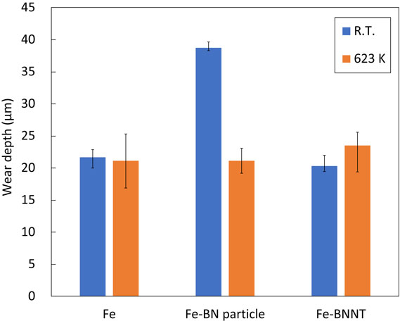
The wear depth of the specimens after the wear test is shown in Fig. 21. Fe-BN particle composite plating showed a larger wear depth than Fe plating at room temperature. BN particles are scale-like, with an average particle size of 10–20 µm, and multiple particles are agglomerated; Fig. 18 shows that the friction coefficient is lower than that of Fe plating at room temperature, which suggests that the BN particles may have peeled off during the wear test and increased the wear depth by shedding BN particles. The Fe-BNNT composite plating had the same wear depth as the Fe plating at room temperature and 623 K. Figure 19 shows that the wear coefficient of Fe-BNNT composite plating increased more than that of Fe plating at 623 K. This may be due to the formation of the compound FeB by heating, which reduced the solid lubricating effect of BNNTs.
3.5 Hardness test
The hardness test results are shown in Fig. 22. The Fe-BN particle composite plating had a higher hardness than that of Fe plating at room temperature, but it became lower than Fe when heated to 523 K. The BN particles are agglomerated in scale-like particles of 10–20 µm. Since the BN crystal surface is more chemically reactive than the interior, the BN particles that contact the Fe plating form compounds at the interface, while the agglomerated interior particles remain soft. Therefore, the hardness may have decreased because the area where BN particles were stacked in the hardness test was the measurement point. The Fe-BNNT composite plating had almost the same hardness as Fe at room temperature, but the hardness increased and became more than twice the value when heated to 523 K. The increase in hardness of the Fe-BNNT composite plating is considered to be due to the formation of hard FeB, as shown in the XRD analysis results in Fig. 11, and the progressive formation of hard FeB. The increase in hardness shown by Fe-BNNT composite plating is considered to be effective in applications to soldering irons that continue to be hit by hard solder.

4. Conclusion
In this study, we evaluated the solderability and erosion of Fe-BN particle and Fe-BNNT composite platings on an SAC305 solder. An EBSD analysis was also conducted to analyze the erosion resistance properties. Based on the experimental results, the following conclusions are drawn.
-
(1)
Fe-BN particle and Fe-BNNT composite platings were successfully fabricated by the electrolytic Fe plating method. Using FIB-SEM/EDS analysis, it was found that BN particles and BNNTs were not only infused on the plating surfaces, but also inside the plating layers.
-
(2)
Fe-BN particle and Fe-BNNT composite plating showed the same, and only a slight decrease in, solder solderability for SAC305 compared to bare Fe plating. In the temperature range of 573 K∼673 K, the solderability and spreading properties of SAC305 were greater than 50%, which makes it possible to apply Fe-BN particle and Fe-BNNT composite plating to a hand-soldering iron tip or a point-soldering machine nozzle.
-
(3)
From the results of the erosion test, it was shown that Fe-BN particle composite plating was 3∼4 times more effective than Fe plating, and Fe-BNNT composite plating was 6∼24 times more effective than Fe plating in reducing erosion with SAC305.
-
(4)
The results of the EBSD analysis showed that a FeB phase was formed in small amounts between Fe grain boundaries. It is expected that FeB is involved in the improvement in erosion resistance properties. If FeB can be efficiently generated in the plating layers, it is believed that the erosion resistance properties will be further improved.
REFERENCES
- 1) Official Journal of the European Union, (2003) L37/19–L37/23, L37/24–L37/38.
- 2) J. Morris and J.M. O’Keefe: Proc. of APEX 2003, 1, (2003) pp. 1–9.
- 3) K. Serizawa, T. Takemoto and K. Yamamoto: Proc. of 15th Symposium on Microjoining and Assembly Technology in Electronics, 15, (2009) pp. 379–382.
- 4) T. Takemoto, H. Nishikawa, K. Serizawa and K.K. Yamamoto: Proc. of 15th Symposium on Microjoining and Assembly Technology in Electronics, 15, (2009) pp. 383–386.
- 5) H. Nishikawa, K. Sabase and T. Takemoto: Proc. of 15th Symposium on Microjoining and Assembly Technology in Electronics, 15, (2009) pp. 387–390.
- 6) T. Takemoto, K. Tomitsuka and H. Nishikawa: Proc. of 13th Symposium on Microjoining and Assembly Technology in Electronics, 13, (2007) pp. 263–226.
- 7) J. Watanabe, N. Sekimori, K. Hatsuzawa, T. Uetani and I. Shohji: J. Phys. Conf. Ser. 379 (2012) 012025. doi:10.1088/1742-6596/379/1/012025
- 8) J. Watanabe, K. Hatsuzawa, S. Ogata, S. Yoshida and I. Shohji: Appl. Sci. 9 (2019) 2724. doi:10.3390/app9132724
- 9) A. Rubio, J.L. Corkill and M.L. Cohen: Phys. Rev. B 49 (1994) 5081–5084. doi:10.1103/PhysRevB.49.5081
- 10) C. Tang, Y. Bando, T. Sato and K. Kurashima: Chem. Commun. (Camb.) (2002) 1290–1291. doi:10.1039/b202177c
- 11) C. Zhi, Y. Bando, C. Tan and D. Golberg: Solid State Commun. 135 (2005) 67–70. doi:10.1016/j.ssc.2005.03.062
- 12) M. Terrones, J.M. Romo-Herrera, E. Cruz-Silva, F. López-Urías, E. Muñoz-Sandoval, J.J. Velázquez-Salazar, H. Terrones, Y. Bando and D. Golberg: Mater. Today 10 (2007) 30–38. doi:10.1016/S1369-7021(07)70077-9
- 13) D. Golberg, Y. Bando, C.C. Tang and C.Y. Zhi: Adv. Mater. 19 (2007) 2413–2432. doi:10.1002/adma.200700179
- 14) N. Ismail, R. Ismail, N.K.A. Nik Ubaidillah, A. Jalar and N.M. Zain: Mater. Sci. Forum 857 (2016) 73–75. doi:10.4028/www.scientific.net/MSF.857.73
- 15) A. Yamauchi, Y. Sekito, K. Kurokawa and J. Tanaka: Proc. of 17th Micro Electronics Symposium, 17, (2007) pp. 107–110.
- 16) T. Kawamoto, A. Yamauchi, S. Kawakubo, A. Irisawa, K. Kurokawa and J. Tanaka: Proc. of 25th Japan Institute of Electronics Packaging, 25, (2011) pp. 165–166.