Abstract
This study introduces a process of severe plastic deformation (SPD) called incremental feeding high-pressure sliding (IF-HPS) where significant grain refinement is possible in an enlarged sheet area. The IF-HPS process is applied to Al alloys such as A1050, A3105, A5052 and A5182. The grain sizes were refined to the submicrometer ranges and the tensile strength increased to almost twice as much as the annealed states. The conditions for the IF-HPS process are optimized so that the tensile strength remains high without initiation of cracks. The process conditions are also investigated to achieve homogeneous development of the tensile properties throughout the processed sheets. It is demonstrated that the IF-HPS process is useful to extend the SPD-processed area without increasing the machine capacity while maintaining enhanced mechanical properties.
1. Introduction
Achieving high-strength is always an important issue in structural materials and this is no exception for the aluminum (Al) alloys. The main procedures for the strengthening of Al alloys are due to grain refinement, fine dispersion of second phase particles, addition of solute atoms and introduction of dislocations by plastic deformation. It was shown that grain refinement to the submicrometer range (so-called ultrafine grains (UFG)) was well achieved using the process of severe plastic deformation (SPD)1,2) and the contribution to the strengthening is significantly large as the strength increases following the Hall-Petch relation.3,4) The extra hardening may occur in the UFG structures when the dislocation density is extremely low within the grains as demonstrated by Haung et al.5) and Kamikawa et al.6) It was also shown that the strength is further increased when aging treatment is undertaken in the UFG samples processed by SPD7–9) as the simultaneous strengthening occurred due to grain refinement and fine precipitation within the grains or grain boundaries. It was demonstrated that the strength reached as high as 1 GPa in age-hardenable Al alloys such as A707510) and A2024.11) Addition of solute atoms was systematically examined by Edalati et al.12) and it was evaluated that the strengthening follows in a better way the Lubasch’s model13) than the Fleischer’s model.14)
Among the SPD processes, the application of high pressure during SPD operation as in the processes of high-pressure torsion (HPT)15–17) and high-pressure sliding (HPS)18,19) is effective for the grain refinement without breaking the samples, and thus both processes are applicable to hard and less ductile materials. However, a major drawback is that the sample is limited to a small size, and thus, upsizing is an important challenging for practical use of the SPD processes.
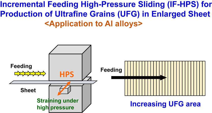
To overcome such limitations, as described in a recent overview paper,20) an incremental feeding technique was introduced in the HPS processes.21,22) It was shown that the SPD-processed area is extended by the combination of the HPS process with incremental feeding of sheet samples as illustrated in Fig. 1, which are called incremental feeding HPS (IF-HPS) process.21,22) In practice, the IF-HPS process has been applied to a Ni-based superalloy (Inconel 718) and it was successful to cover a square area with 100 × 100 mm sheet by the IF-HPS process without increasing the machine capacity.22) The samples processed by the IF-HPS process exhibited superplastic elongations well more than 400% because of the development of UFG structures. In particular, the IF-HPS-processed sheet permitted cup forming at a temperature as low as 1083 K, whereas the sheet was fractured at the same forming condition unless it was processed by the IF-HPS.22)
In this study, the IF-HPS process is applied, for the first time, to commercially available aluminum alloys such as A1050, A3105, A5052 and A5182 to achieve an optimal processing condition for homogeneous development of the mechanical properties such as strength and ductility. The microstructures after processing by IF-HPS were observed by transmission electron microscopy (TEM). The mechanical properties were examined by tensile testing including Vickers microhardness measurement.
2. Experimental
The aluminum alloys used in this study are A1050, A3105, A5052 and A5182 with compositions shown in Table 1. They were received in a form of sheets with 1.5 mm thickness for the A1050 and with 1 mm thickness for the rest of the alloys. The samples for the IF-HPS process were cut to the dimensions with 60 mm (or 100 mm) width and 300 mm length.
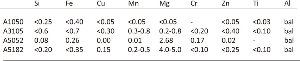
Table 1 Al alloys and their chemical compositions in mass%.
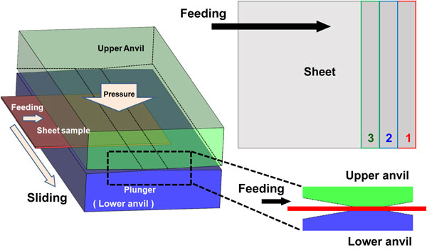
The IF-HPS process was conducted at room temperature under an applied pressure of 1 or 2 GPa with sliding speeds of 1 or 10 mm/s using a flat-type anvils with the straining area with 10 mm width and 100 mm length. As illustrated in Fig. 1, the sheet sample was fed each after sliding for straining with the feeding distance of 10 mm without superposition on the slid area. Further processing procedures were described in detail earlier.22)
Vickers microhardness was measured using a microhardness tester (Mitutoyo HM-102) with an applied load of 4.9 N for a dwell time of 15 s with an accuracy of ±2 HV. Tensile specimens were cut from IF-HPS-processed sheets using an electrical discharge machine (EDM) with the dimensions as shown in Fig. 2, where the tensile axis is parallel to the sliding direction. Tensile tests were conducted with an initial strain rate of 2.0 × 10⁻³ s−1 at room temperature.
For microstructural observation by transmission electron microscopy (TEM), disks with 3 mm diameter were extracted at positions close to the tensile specimens using the EDM. The disks were ground mechanically to a thickness of 0.15 mm and further thinned by a twin-jet electropolishing technique using a mixture of 10 vol% perchloric acid, 20 vol% glycerol and 70 vol% methanol at ∼253 K. TEM was undertaken using a Hitachi H8100 microscope operating at an accelerating voltage of 200 kV.
3. Results
3.1 Optimization for IF-HPS process conditions
3.1.1 Effect of sliding mode on tensile strength and ductility
Figure 3 and Fig. 4 show the stress-strain curves of the A1050 and A5052 alloys, respectively, after processing by IF-HPS under 2 GPa with the sliding speed of 10 mm/s for the total sliding distance of 15 mm. For comparison, Fig. 3 and Fig. 4 include the stress-strain curves of the specimens in a fully annealed state and the as-received state (equivalent to H34). In this study, the four different sliding modes were adopted for the IF-HPS process. The first mode is designated as “X = 15-1P” representing that the sliding distance is 15 mm and the straining was made through 1 pass for 1 way. The second mode as “X = 7.5-2R” representing that the sliding distance for one way is 7.5 mm but the sliding was reversed so that the two sliding passes were employed to give the total sliding distance of 15 mm. Likewise, for the third and fourth modes designated as “X = 5-3R” and “X = 3-5R”, the sliding distances for one way were 5 and 3 mm with 3 and 5 passes including reverse motions so that the total sliding distance was kept 15 mm, respectively.
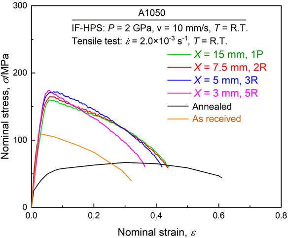
Comparison between Fig. 3 and Fig. 4 shows that the difference is obvious between the stress-strain curves of the A1050 and A5052 alloys. For the A1050 alloy, the stress-strain behavior is almost similar to each other with the tensile strengths within the range of 160–170 MPa and the total elongation within the range 0.37–0.44. For the A5052 alloy, the stress-strain behavior is significantly affected by the sliding mode: the highest tensile strength is achieved with 700 MPa for the sample processed through X = 15-1P while the lowest with 320 MPa for the sample through X = 3-5R. The trend is opposite in the total elongation: the smallest is 0.12 and the largest is 0.27 obtained after processing through X = 15-1P and X = 3-5R, respectively.
3.1.2 Effect of applied pressure and sliding speed
It is reasonable that the flow stress level is higher in the A5052 alloy than the A1050 alloy because the A5052 alloy contains 2.68 mass% of Mg and thus receives a strong effect of solid solution hardening. However, a question arises why the stress-strain behavior is different in the A5052 alloy depending on the sliding modes despite the same total sliding distance which is 15 mm. It is most probable that the strain was not properly introduced as the number of the reciprocation increases. This is because the reciprocation system in the processing machine may involve some ambiguity in the sliding distance due to inertial.
Another reason may be because the slippage occurs between the sample and anvils as discussed earlier.23) The slippage becomes more significant as the material is harder and the applied pressure is lower. It is more likely that the slippage occurred in the A5052 alloy than in the A1050 alloy because the strength of the A5052 is high in comparison with that of the A1050 as it is evident from the comparison between Fig. 3 and Fig. 4.
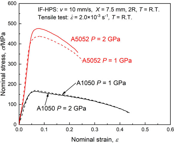
Figure 5 delineates the stress-strain curves of the samples processed under 1 and 2 GPa for the A1050 and A5052 alloys to examine the effect of applied pressure when the IF-HPS process was conducted with the sliding mode of X = 7.5-2R. Whereas no appreciable difference is observed in the A1050 alloy, the flow stress level is invariably lower by ∼40 MPa in the A5052 alloy when the applied pressure is 1 GPa than 2 GPa. It is thus suggested that the slippage might have occurred in the A5052 alloy but not in the A1050 alloy.
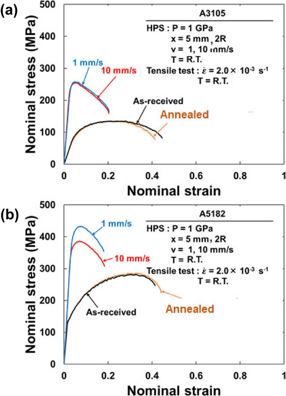
The effect of the sliding speed was further examined in the A3105 and A5182 alloys and the stress-strain curves are delineated in Fig. 6(a) and (b), respectively. The alloys were processed under 1 GPa with the sliding speeds of 1 and 10 mm/s through the sliding mode of X = 5-2R. Whereas no appreciable difference is found in the A3105 alloy, the difference is appreciable in the A5182 alloy where the flow stress is invariably lower when the sliding was made with the speed of 10 mm/s than 1 mm/s. Because the A5182 alloy is harder than the A3105 alloy, the effect of slippage is significant in the A5182 alloy in comparison with the A3105 alloy as shown earlier.23)
3.1.3 Microstructural observation by TEM
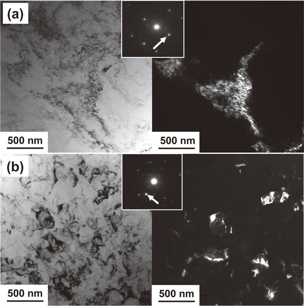
Figure 7 and Fig. 8 are TEM micrographs taken from the samples processed for the A1050 and A5052 alloys through the sliding modes of (a) X = 3-5R and (b) X = 15-1P, respectively. Bright-field images are shown on the left and dark-field images on the right taken from the diffracted beams indicated by arrows in the selected area electron diffraction (SAED) patterns of the insets. Grains with the sizes of ∼1 µm are visible for the A1050 alloy, and there appears to be no significant microstructural difference between the samples processed through X = 3-5R and X = 15-1P, and grain boundaries are rather well-defined. The similarity of the microstructure is consistent with the stress-strain behavior in Fig. 3 where no significant difference in the tensile strength and the total elongation. These observations are also consistent with earlier reports on high purity Al (99.99%) that the strength as well as grain structure remains unchanged with further straining.24) Estimating the contribution of grain refinement to the total strength using the Hall-Petch relation3,4) (ΔσGB = k/d1/2 where k = 0.041 MPa/m1/2 for pure Al25)), it follows that ΔσGB ∼ 40 MPa which comes to ∼30% of the yield stress (∼130 MPa from Fig. 3). Although dislocation density was not measured in this study, the contribution of dislocations to the total strength may be estimated as ∼50% (∼65 MPa) from the approximation that the contributions of dislocations and grain boundaries are negligibly small to the yield stress at the annealed state (∼25 MPa from Fig. 3).

By contrast, microstructural features in the A5052 alloys are different from those for the A1050 alloy: grain boundaries are ill-defined and the grain size appears to be below 1 µm in the sample processed through X = 3-5R, while the sample processed through X = 15-1P exhibits the grain size well reduced to ∼100 nm. It is considered that such microstructural features give rise to the difference in the stress-strain behavior shown in Fig. 4 and the former feature is attributed to an insufficient introduction of strain due to slippage. Estimating the contribution of grain refinement to the total strength, it turns out that ΔσGB = 80 MPa (∼40%) for d = ∼1 µm after X = 3-5R and ΔσGB = 255 MPa (∼40%) for d = ∼100 nm after X = 15-1P, where k = 0.08 MPa/m1/2 for Al alloys11) was used in the Hall-Petch relation and we have referred to Fig. 4 for the corresponding yield stresses, 200 and 650 MPa, respectively. For the contribution of dislocations to the total strength, it is rather difficult to make a rigorous estimation because of the presence of second phase particles when we use the same procedure as for the A1050 alloy. However, it is deduced that the contribution of dislocations to the total strength is ∼30% for the sliding mode of X = 3-5R and ∼50% for X = 15-1P. This estimation has been made using the approximation that not only the contributions of dislocations and grain boundaries are negligibly small at the annealed state (∼60 MPa from Fig. 4) but also the effects of the second phase particles and the solute atoms on the yield stress are essentially the same between the processed state and the annealed state.
3.1.4 Avoiding crack initiation
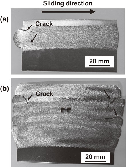
It is thus concluded that the best processing mode is to use the sliding mode without adopting the reciprocation, as X = 15-1P, and thus the highest strength is achieved as shown in Fig. 4. By contrast, any processing mode adopted in this study reaches the highest strength in the A1050 alloy. It is important to note for practical application that the sheet should be processed without initiation of cracks. Surface observation revealed that cracks appeared in the A5052 alloy after the first pass as shown in Fig. 9(a) and such cracks propagated after further consecutive processings through X = 15-1P. Figure 9(b) shows appearance of some cracks after 5 consecutive processings through X = 7.5-2R under 2 GPa. Although the initiation of such cracks did not occur when the applied pressure is reduced to 1 GPa, the tensile strength is decreased because of the slippage as discussed in association with Fig. 5. For the A1050 alloy, when the sheet was processed through X = 15-1P, some small cracks were visible at the edges of the sheet in the sliding direction. Thus, optimization is required between the tensile strength and the formation of cracks. It is suggested that strain should be gradually accumulated by adopting reciprocation as X = 3-5R or X = 5-3R but it is important to avoid a large gradient of strain within short distance as X = 15-1P.
The IF-HPS process was further applied to the A1050, A3105 and A5182 alloys under 1 GPa with sliding speed of 10 mm/s through X = 5-2R. The stress-strain curves are delineated in Fig. 10(a), (b) and (c), respectively, to examine the homogeneous development of properties such as tensile strength and ductility. Four positions where tensile specimens were extracted are labeled 1, 2, 3 and 4 in the corresponding processed sheets as shown in the insets. It should be noted that the feeding of the sheet was made from right to left so that straining by HPS was initiated from the left side of the sheet. Feeding and straining were repeated until the termination at position 4. The stress-strain behavior is almost the same for all alloys except for positions 1 of the A3105 and A5182 alloys where the flow stress level is invariably lower. This suggests that the IF-HPS-processed sheet is homogeneous in the tensile strength and ductility except the area after the first processing in the A3105 and A5182 alloys. This should be due to the fact that strain was not fully introduced because straining by the first sliding was made at the edge of the sheet so that constraining effect by the surrounding was insufficient. The simulation using a finite element method (FEM) by Takizawa et al.22) reported a similar trend on the IF-HPS process of an Inconel 718 alloy. However, this edge effect is not appreciable in the A1050 alloy because the sample is soft. It appears that the trend is more prominent as the materials are harder so that more strain is required to reach a hardness saturation where the hardness remains unchanged with straining. It is thus suggested that the IF-HPS process should be started away from the sample edge.

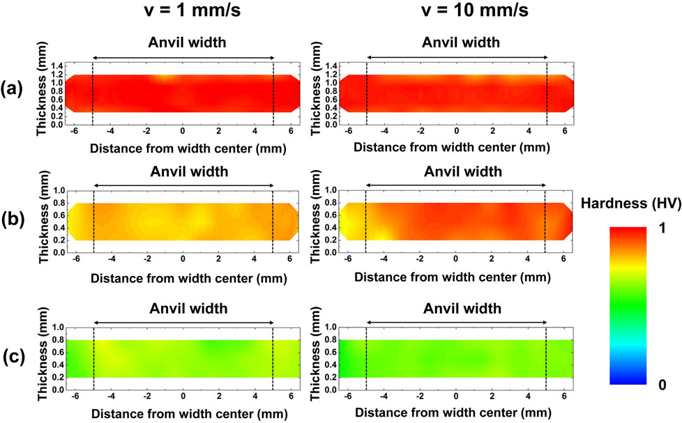
The above side effect was further investigated by measuring the hardness across the cross section of the sheets. Figure 11(a), (b) and (c) are hardness variations on the cross sections of the processed sheets in the A1050, A3105 and A5182 alloys after sliding with speeds of 1 mm/s (left) and 10 mm/s (right) for the total sliding distance of 10 mm through the sliding mode of X = 5-2R. The color code in the mapping was defined by normalizing measured hardnesses with respect to the hardness at the saturation, which are 53, 115 and 205 HV for the A1050, A3105 and A5182 alloys, respectively. The hardness saturation generally reaches in any metallic materials when the hardness is plotted as a function of imposed strain as reported earlier.26) In this study, the hardness saturation was determined by conducting HPT process on the alloys and by plotting the hardness against the imposed strain. It is found that the hardness increase is not only limited to the area where strain was imparted but also it is extended to the surrounding areas. Thus, it is reasonable to expect that the surrounding areas act as a barrier against the outward material flow. However, if the surrounding material does not exist, the material in the straining area is less constrained because the outward flow of the material more occurs. Consequently, strain was less accumulated within the straining area. It should be also noted that homogenous development throughout the cross sections was better achieved with the sliding speed of 1 mm/s than 10 mm/s. The saturation has reached in the A1050 alloy, while it has not in the A3105 and A5182 alloys with the A3105 alloy more hardened than the A5182 alloy: 80% and 60% of the saturated hardness for the A3105 and A5182 alloys, respectively. This trend is in good accordance with the stress-strain behavior shown in Fig. 10(a), (b) and (c) where the stress-strain curves are almost the same for all the four positions in the A1050 alloy but the flow stress level is lower in position 1 than in positions 2, 3 and 4.
4. Summary and Conclusions
In this study, the IF-HPS process was applied to four types of Al alloys such as A1050, A3105, A5052 and A5182 alloys. The process conditions were optimized to achieve high tensile strength without initiation of cracks. The conclusions are summarized as follows.
-
(1)
The application of the IF-HPS process to A1050 and A5052 alloys showed that the tensile strength and the total elongation are almost the same in the A1050 alloy irrespective of the sliding mode which designates the numbers of reciprocation and the sliding distance of each pass for the total sliding distance, while the tensile strength decreased and the total elongation increased as the sliding mode changes towards the ones with more numbers of the reciprocation with short sliding distances as in the order of X = 15-1P, X = 7.5-2R, X = 5-3R and X = 3-5R for the total sliding distance of 15 mm.
-
(2)
The difference between the stress-strain behaviors of the A1050 and A5052 alloys arises because the A5052 alloy is harder and less ductile than the A1050 alloy due to the effect of solid solution hardening by the major inclusion of Mg.
-
(3)
The decrease in the flow stress level observed in the A5052 alloy is ascribed to the slippage between the sheet sample and the anvils, which is more likely to occur when the applied pressure is lower, the sliding speed is higher and the sample is harder.
-
(4)
Crack initiation is less likely to occur as the sliding mode involves more numbers of reciprocations with shorter sliding distances. Thus, for the IF-HPS processing, an optimal condition for high tensile strength without visible cracks in the A1050 and 5052 alloys are X = 7.5-2R with the sliding speed of 2 mm/s under 2 GPa and 1 GPa, respectively.
-
(5)
Homogeneous development of tensile properties should be achieved by staring IF-HPS process with an ample margin from the edge of the sheet but not next to the side edge.
Acknowledgment
This work was supported by a Grant-in-Aid for Scientific Research (A) from the MEXT, Japan (19H00830).
REFERENCES
- 1) R.Z. Valiev, R.K. Islamgaliev and I.V. Alexandrov: Prog. Mater. Sci. 45 (2000) 103–189. doi:10.1016/S0079-6425(99)00007-9
- 2) R.Z. Valiev, Y. Estrin, Z. Horita, T.G. Langdon, M.J. Zehetbauer and Y.T. Zhu: JOM 58(4) (2006) 33–39. doi:10.1007/s11837-006-0213-7
- 3) E.O. Hall: Proc. Phys. Soc. B 64 (1951) 747–753. doi:10.1088/0370-1301/64/9/303
- 4) N.J. Petch: J. Iron Steel Inst. 174 (1953) 25–28.
- 5) X. Huang, N. Hansen and N. Tsuji: Science 312 (2006) 249–251. doi:10.1126/science.1124268
- 6) N. Kamikawa, N. Tsuji, X. Huang and N. Hansen: Acta Mater. 54 (2006) 3055–3066. doi:10.1016/j.actamat.2006.02.046
- 7) W.J. Kim, C.S. Chung, D.S. Ma, S.I. Hong and H.K. Kim: Scr. Mater. 49 (2003) 333–338. doi:10.1016/S1359-6462(03)00260-4
- 8) S. Lee, Z. Horita, S. Hirosawa and K. Matsuda: Mater. Sci. Eng. A 546 (2012) 82–89. doi:10.1016/j.msea.2012.03.029
- 9) T. Masuda, Y. Takizawa, M. Yumoto, Y. Otagiri and Z. Horita: Mater. Trans. 58 (2017) 1647–1655. doi:10.2320/matertrans.M2017242
- 10) P.V. Liddicoat, X.Z. Liao, Y. Zhao, Y. Zhu, M.Y. Murashkin, E.J. Lavernia, R.Z. Valiev and S.P. Ringer: Nat. Commun. 1 (2010) 63(7p). doi:10.1038/ncomms1062
- 11) T. Masuda, X. Sauvage, S. Hirosawa and Z. Horita: Mater. Sci. Eng. A 793 (2020) 139668. doi:10.1016/j.msea.2020.139668
- 12) K. Edalati, D. Akama, A. Nishio, S. Lee, Y. Yonenaga, J.M. Cubero-Sesin and Z. Horita: Acta Mater. 69 (2014) 68–77. doi:10.1016/j.actamat.2014.01.036
- 13) R. Labusch: Acta Metall. 20 (1972) 917–927. doi:10.1016/0001-6160(72)90085-5
- 14) R.L. Fleischer: Acta Metall. 11 (1963) 203–209. doi:10.1016/0001-6160(63)90213-X
- 15) P.W. Bridgman: Phys. Rev. 48 (1935) 825–847. doi:10.1103/PhysRev.48.825
- 16) A.P. Zhilyaev and T.G. Langdon: Prog. Mater. Sci. 53 (2008) 893–979. doi:10.1016/j.pmatsci.2008.03.002
- 17) K. Edalati and Z. Horita: Mater. Sci. Eng. A 652 (2016) 325–352. doi:10.1016/j.msea.2015.11.074
- 18) T. Fujioka and Z. Horita: Mater. Trans. 50 (2009) 930–933. doi:10.2320/matertrans.MRP2008445
- 19) Y. Takizawa, T. Masuda, K. Fujimitsu, T. Kajita, K. Watanabe, M. Yumoto, Y. Otagiri and Z. Horita: Metall. Mater. Trans. A 47 (2016) 4669–4681. doi:10.1007/s11661-016-3623-3
- 20) Z. Horita, Y. Tang, T. Masuda and Y. Takizawa: Mater. Trans. 61 (2020) 1177–1190. doi:10.2320/matertrans.MT-M2020074
- 21) Y. Takizawa, K. Watanabe, T. Kajita, K. Sumikawa, T. Masuda, M. Yumoto, Y. Otagiri and Z. Horita: J. Jpn. Inst. Met. Mater. 82 (2018) 25–31. doi:10.2320/jinstmet.J2017038
- 22) Y. Takizawa, K. Sumikawa, K. Watanabe, M. Yumoto, Y. Kanai, Y. Otagiri and Z. Horita: Metall. Mater. Trans. A 49 (2018) 1830–1840. doi:10.1007/s11661-018-4534-2
- 23) K. Edalati, Z. Horita and T.G. Langdon: Scr. Mater. 60 (2009) 9–12. doi:10.1016/j.scriptamat.2008.08.042
- 24) Y. Ito and Z. Horita: Mater. Sci. Eng. A 503 (2009) 32–36. doi:10.1016/j.msea.2008.03.055
- 25) N. Kamikawa, X. Huang, N. Tsuji and N. Hansen: Acta Mater. 57 (2009) 4198–4208. doi:10.1016/j.actamat.2009.05.017
- 26) K. Edalati and Z. Horita: Mater. Trans. 51 (2010) 1051–1054. doi:10.2320/matertrans.M2009431