Abstract
A rotating magnetic field was applied during the solidification of Al–Si–Fe alloys (Si = 5 mass% or 10 mass% and Fe = 0.5 mass% or 1 mass%) and the effect of electromagnetic stirring on the area and shape of the intermetallic compounds was studied. The phases formed during solidification of the alloys were not influenced by electromagnetic stirring. The alloys consisted of α-Al, Si and intermetallic β-Al9Fe2Si2. At coil current frequencies above 10 Hz, electromagnetic stirring induced fragmentation of dendritic α-Al, giving rise to coarsening of the β-Al9Fe2Si2 present between the fragmented α-Al grains. The application of electromagnetic stirring at coil current frequencies above 80 Hz decreased the aspect ratio of β-Al9Fe2Si2 in Al–10 mass%Si–1 mass%Fe, while no such decrease was identified in Al–5 mass%Si–0.5 mass%Fe, Al–5 mass%Si–1 mass%Fe or Al–10 mass%Si–0.5 mass%Fe. It was found that the shape of the β-Al9Fe2Si2 phase formed under forced flow of the melt depended significantly on the stirring intensity and the solid fraction of the melt at which intermetallic compounds were formed.
1. Introduction
Owing to their superior casting fluidity, Al–Si alloys are widely used for casting products with thin and complex shapes. Casting alloys are often derived from scrap alloys and thus contain a variety of impurities. Iron is a common impurity in recycled Al–Si alloys. The solubility of Fe in solid Al and Si is low, while that in liquid Al–Si is relatively high, giving rise to the frequent formation of Al–Si–Fe intermetallic compounds during solidification.1,2) The formation of Al–Si–Fe intermetallic compounds not only increases the strength of the products but also suppresses soldering during die casting. However, the formation of Al–Si–Fe intermetallic compounds is often considered to be detrimental to ductility.2–4) The mechanical properties of Al–Si–Fe alloys significantly depend on the morphology of Al–Si–Fe intermetallic compounds. Moustafa reported that the precipitation of β-Al9Fe2Si2 platelets caused the formation of shrinkage cavities because β-Al9Fe2Si2 prevents the flow of liquid metal.5) The intermetallic monoclinic β-Al9Fe2Si2 phase (a = b = 0.612 nm, c = 4.15 nm and β = 91°) is also known as β-Al5FeSi,6–8) hereafter referred to as β-AlFeSi. When Mn is added to Al–Si–Fe alloys, β-AlFeSi platelets can be transformed into the more compact form of polygonal Al15(Fe,Mn)3Si2, reducing the negative effect of β-AlFeSi and thus improving the mechanical properties.9–11) The reliability of Al–Si cast products is significantly related to the morphology of β-AlFeSi.
Casting using semi-solid metal slurries is effective for preparing near-net shaped metal products.12,13) To fabricate slurries containing homogeneously dispersed fine spherical/rosette shaped solid metal, the application of an external field to produce vibration and stirring is a useful technique. Mechanical or electromagnetic vibration/stirring exerted on an Al alloy melt enhances the flow with a high solute content into a mushy zone, resulting in fragmentation of dendritic α-Al.14–19) Ultrasonic vibration induces not only fragmentation of α-Al but also grain refinement of Al–Si–Fe intermetallic compounds.20,21) High-intensity ultrasonic vibration causes microstructural changes due to cavitation and acoustic streaming. However, the question arises as to how the forced melt flow induced by stirring affects the morphology of intermetallic compounds. One criterion for dendrite fragmentation22) is that it becomes more frequent as the liquid flow permeability becomes higher. Because the permeability is related to the solid fraction of the melt, the shape of the intermetallic compounds formed under forced melt flow would be affected by the solid fraction of the melt at which intermetallic compounds start to grow. However, the relationship between the shape of the intermetallic compounds and the solid fraction of the melt is not clearly understood. There have been some studies on the effect of electromagnetic stirring (EMS) on the shape of β-AlFeSi phases.23,24) Nafisi et al. solidified Al–7 mass%Si–0.8 mass%Fe under forced melt flow imposed by a rotating magnetic field and studied the effect of stirring on the shape of β-AlFeSi phases. Mikolajczak and Ratke performed upward solidification of Al–Si–Fe alloys (Si = 5–9 mass% and Fe = 0.2–1.0 mass%) at a constant cooling rate under electromagnetic stirring and studied the effect of the alloy composition on the shape of β-AlFeSi phases. In these previous studies, the current frequency applied to the electromagnetic coil was constant at 50 Hz, and thus the EMS intensity was fixed because the intensity of the melt flow induced by the rotating magnetic field increased with increasing current frequency. In the present study, to determine the relationship between the EMS intensity and the shape of intermetallic β-AlFeSi phases, the effect of the current frequency (f) applied to the stator on the final microstructure was studied. With increasing f, the rotational speed of the alternating magnetic field and the azimuthal component of the EMS increased. The relationship between the Al–Si–Fe alloy composition and the shape of β-AlFeSi phases formed under forced melt flow was also investigated.
2. Experimental Procedure
Al–Si–Fe alloys with four different compositions were solidified in this study. Table 1 shows the compositions of the alloys as determined by optical emission spectroscopy. During the solidification of the alloys, primary α-Al is formed, followed by the formation of β-AlFeSi. Note that the alloys exhibit different solid fractions of the melt at the formation of β-AlFeSi. The concentrations of elements except Al, Si and Fe were almost the same in the Al–Si–Fe alloys. Figure 1 shows a schematic of the equipment used for solidification with EMS. A three-phase coil having an output of 2.2 kW and a bore radius of 100 mm was used to generate a rotating magnetic field and induce forced flow of the Al–Si–Fe alloy melt. 100 g of the Al–Si–Fe alloy was loaded in a JIS SUS304 crucible with an inner diameter of 50 mm and a height of 60 mm. Boron nitride coating was applied on the inner wall of the crucible, preventing the reaction between the crucible and the Al–Si–Fe alloy melt. The crucible was placed in an electric furnace and the Al–Si–Fe alloy was kept at 720°C for 10 min to melt the alloy. After the dross on the melt was removed, the crucible was placed in the stator, and EMS was applied until the melt was completely solidified. The Al–Si–Fe alloy was solidified in air at a cooling rate of approximately 1°C s−1. The range of f was 10–120 Hz and was controlled using an inverter. The magnetic field (B) near the wall of the crucible was 18 mT at 10 Hz and 24 mT at 40–120 Hz. Note that the EMS intensity increased in accordance with B2f. The Al–Si–Fe alloy with a radius of 50 mm and a height of 20 mm was cut into quarters and then a sample was sectioned at the middle of the height of the quarter. The sample mounted using an epoxy resin was ground with SiC paper and was polished down to 0.04 µm with polycrystalline diamond and colloidal silica suspensions. To make the shape of intermetallic β-AlFeSi clearer, the sample was etched with a 0.5% HF solution for 30 s. The microstructure near the periphery of the sample was observed and optical images of typical microstructures were obtained using a digital microscope (VHX-5000, Keyence). The field of view for the image analysis was 1130 × 850 µm2 in which 70∼210 intermetallic compounds were present. Three optical images were analyzed to construct a histogram of the surface area and the aspect ratio of the intermetallic β-AlFeSi; thus, the histograms are based on 250∼600 intermetallic β-AlFeSi grains. The aspect ratio is defined as the ratio of the length to the width of the intermetallic β-AlFeSi grains. Image analysis software (Image-Pro, ver. 10.0.10) was used for thresholding the optical images. Because the size of the optical image was 1600 × 1200 pixels, the spatial resolution was only about 1 µm; thus, the image analysis was not able to identify grains with an area of less than 1 µm2. Grains with an area of 1–10 µm2 were not counted in the histograms because it was difficult to distinguish the grains from contamination.

Table 1 Composition of Al–Si–Fe alloy samples used in this study.
3. Results
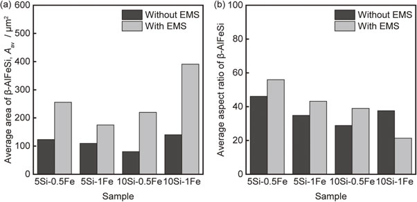
Figure 2 shows optical images of a cross-section of 10Si–0.5Fe, indicating the presence of three different phases. In order of brightness, they were α-Al, Si and intermetallic β-AlFeSi. Dendritic α-Al was identified in 10Si–0.5Fe solidified without EMS (Fig. 2(a)). Between the dendrite arms, β-AlFeSi and Si were present. With EMS at f ≥ 10 Hz, the α-Al dendrites were equiaxed, and β-AlFeSi was found between these equiaxed grains (Fig. 2(b)–(e)). In addition, α-Al formed during solidification of 5Si–1Fe, 10Si–0.5Fe and 10Si–1Fe was fragmented by EMS at f = 10–120 Hz. Compared to α-Al, the effect of EMS on the morphology of β-AlFeSi was ambiguous because the field of view in Fig. 2 was too large to identify the shape. To clarify the effect of EMS on the morphology of intermetallic compounds, optical images of β-AlFeSi in 5Si–0.5Fe, 5Si–1Fe, 10Si–0.5Fe and 10Si–1Fe were acquired at higher magnification, as shown in Figs. 3 and 4. The intermetallic β-AlFeSi phase exhibited plate-like grains, and the length of these grains solidified without EMS was about 100 µm in 5Si–0.5Fe and 5Si–1Fe (Fig. 3). 10Si–0.5Fe and 10Si–1Fe also exhibited plate-like β-AlFeSi grains with a length of about 100 µm (Fig. 4). The maximum length of β-AlFeSi grains in 5Si–0.5Fe, 5Si–1Fe and 10Si–0.5Fe solidified using EMS with f = 120 Hz was 500–1000 µm, which is 5∼10 times higher than in the absence of EMS, indicating that the overall β-AlFeSi increased. The length of β-AlFeSi grains in 10Si–1Fe in the presence of EMS was almost the same as that without EMS. However, EMS caused an increase in the grain width, resulting in an increase in the overall area. These results indicate that the effect of EMS on the β-AlFeSi grain shape depended on the alloy composition. Figures 5–8 show histograms of the surface area and the aspect ratio of β-AlFeSi in 5Si–0.5Fe, 5Si–1Fe, 10Si–0.5Fe and 10Si–1Fe, respectively. EMS was performed at 120 Hz. In the absence of EMS, almost all β-AlFeSi grains in 5Si–0.5Fe have an area of less than 1000 µm2, while in the presence of EMS, grains with an area of more than 1000 µm2 account for about 10% of the total area (Fig. 5(a)). Similar results were also found for other Al–Si–Fe alloys. In the presence of EMS, 3–10% of β-AlFeSi grains in 5Si–1Fe (Fig. 6(a)), 10Si–0.5Fe (Fig. 7(a)) and 10Si–1Fe (Fig. 8(a)) exhibited surface areas larger than the maximum area without EMS. The cumulative percentage in the area histograms indicates that EMS influenced the area distribution of β-AlFeSi above the median value. The histograms of the area of β-AlFeSi suggest that EMS did not cause fragmentation of β-AlFeSi. The effect of EMS on the aspect-ratio distribution was different from that for the surface area. The cumulative percentage in the aspect-ratio histograms showed no significant effect of EMS for 5Si–0.5Fe (Fig. 5(b)), 5Si–1Fe (Fig. 6(b)) and 10Si–0.5Fe (Fig. 7(b)), while a 50% decrease in the median aspect ratio was produced by EMS for 10Si–1Fe (Fig. 8(b)). β-AlFeSi with an aspect ratio of more than 200 accounted for 5% for 10Si–1Fe without EMS, while all β-AlFeSi grains in 10Si–1Fe solidified with EMS exhibited an aspect ratio of less than 200. Figure 9 shows the effect of EMS on the average surface area and aspect ratio of β-AlFeSi in the Al–Si–Fe alloys. The average surface area in the presence of EMS was 2∼3 times higher than that without EMS (Fig. 9(a)). The effect of EMS on the aspect ratio depended on the alloy composition: the aspect ratio for 5Si–0.5Fe, 5Si–1Fe and 10Si–0.5Fe solidified in the presence of EMS was slightly higher than that without EMS, while a decrease in the aspect ratio using EMS was found for 10Si–1Fe.

4. Discussion
4.1 Effect of EMS on area of β-AlFeSi
The increase in β-AlFeSi area caused by EMS is thought to be associated with fragmentation and equiaxed growth of primary α-Al. It is widely known that forced flow of a melt facilitates fragmentation at the bottom of the dendrite arm due to flow of a melt with a high solute content into the mushy region.25–27) The forced flow reduces the thermal gradient in the melt and thus the undercooled region in the melt is extended, providing favorable conditions for the growth of equiaxed grains. Figure 10 illustrates the effect of the morphology of primary α-Al on the subsequent growth of β-AlFeSi. When EMS is not applied during solidification, primary α-Al grows in a dendritic form and nucleation and growth of β-AlFeSi occur between the dendrite arms (Fig. 10(a)). It has been reported that β-AlFeSi exhibits anisotropic growth kinetics.28,29) Once nucleated, β-AlFeSi continues to grow in a faceted plate-like form until the primary α-Al impinges on the growth. This indicates that it is difficult to increase the β-AlFeSi content in the space between narrow dendrite arms. When EMS is applied during solidification, dendrite α-Al becomes fragmented and primary α-Al grows in an equiaxed form (Fig. 10(b)). Nucleation of β-AlFeSi could occur between equiaxed grains. Considering that the equiaxed α-Al could be agglomerated, EMS could expand the space where β-AlFeSi grows without impingement, allowing the propagation of β-AlFeSi in the preferential growth direction. It should be noted that coarsening of β-AlFeSi grains in Al–Si–Fe alloys was identified for EMS above 10 Hz where α-Al grows in an equiaxed form (Fig. 2), reflecting an increase in β-AlFeSi area by EMS associated with equiaxed growth of primary α-Al.

The relationship between the aspect ratio of β-AlFeSi grains and EMS is expected to be influenced by the solid fraction of the melt from which β-AlFeSi is formed. Figure 11 shows the volume fraction of all phases in the Al–Si–Fe alloys as a function of temperature calculated using Thermo-Calc.30) The Al–Si–Fe alloys used in this study consist of three phases: α-Al, β-AlFeSi and Si. α-Al is the primary phase and β-AlFeSi is the only intermetallic compound formed during solidification. During the solidification of 5Si–0.5Fe, primary α-Al is formed at 629°C, followed by the formation of β-AlFeSi at 592°C and the eutectic reaction at 575°C (Fig. 11(a)). 5Si–1Fe (Fig. 11(b)) and 10Si–1Fe (Fig. 11(d)) also exhibit the formation of primary α-Al and then β-AlFeSi, while β-AlFeSi in 10Si–0.5Fe is formed by the eutectic reaction Liquid → α-Al + β-AlFeSi + Si (Fig. 11(c)). The Al–Si–Fe alloys exhibit different solid fractions in the melt when β-AlFeSi is formed: the ratio of primary α-Al to the melt when β-AlFeSi is formed is 56%, 38%, 21% and 9% for 5Si–0.5Fe, 5Si–1Fe, 10Si–0.5Fe and 10Si–1Fe, respectively. Because the liquid flow permeability increases with decreasing solid fraction of the melt, 10Si–1Fe would exhibit the highest permeability when β-AlFeSi starts to grow. The growth kinetics of the faceted plate-like β-AlFeSi depends on the crystallographic direction.28,29) Nucleated β-AlFeSi propagates in the preferential growth direction by lateral growth, while the growth on the faceted plate surface continues by a ledge growth mechanism. The thickening process for the faceted plate is limited by attachment and diffusion of the solute. The forced flow of the melt by EMS could influence both lateral and ledge growth because EMS could influence the thermal and solutal field near β-AlFeSi. Using EMS, the lateral growth velocity could decrease because the thermal gradient in the melt is lowered by forced convection. Conversely, EMS would increase the velocity of ledge growth because stirring can enhance rejection and diffusion of the solute. The forced flow of the melt could decrease the velocity of lateral growth and increase the thickening velocity of the faceted plate, leading to a decrease in the aspect ratio of β-AlFeSi in 10Si–1Fe (Figs. 4(b), 8(b) and 9(b)). The aspect ratio of β-AlFeSi in 5Si–0.5Fe and 5Si–1Fe increased slightly using EMS (Figs. 5, 6 and 9), indicating that melt stirring by EMS did not influence the thermal and solutal fields during the solidification of 5Si–0.5Fe and 5Si–1Fe because the solid fraction of the melt would be too high to induce forced flow in the semi-solid liquid. No decrease in the aspect ratio was identified in 10Si–0.5Fe (Figs. 7 and 9). Because β-AlFeSi is formed by a eutectic reaction in 10Si–0.5Fe, the permeability would show a sharp decrease upon the formation of β-AlFeSi, indicating that melt stirring did not influence the thermal and solutal fields near β-AlFeSi.

It should be noted that a decrease in the aspect ratio of β-AlFeSi was caused by EMS above 80 Hz. Figure 12 shows optical images of cross-sections in 10Si–1Fe solidified using EMS at 10, 40 and 80 Hz. The microstructure of 10Si–1Fe solidified without EMS (f = 0 Hz) is shown in Fig. 12(a). No significant change in the β-AlFeSi aspect ratio was found for EMS at 10 Hz (Fig. 12(b)). Some β-AlFeSi solidified at 40 Hz exhibited a lower aspect ratio than that solidified at 0 and 10 Hz (Fig. 12(c)). The microstructure solidified at 80 Hz (Fig. 12(d)) was almost the same as that at 120 Hz (Fig. 4(b)): EMS at 80 Hz is sufficient to cause a decrease in the aspect ratio. When the number of pole pairs, the magnetic field, the bore radius and the electrical conductivity of the melt are constant, the azimuthal component of the electromagnetic force related to the intensity of stirring increases with increasing current frequency.22,31) The intensity of stirring imposed by EMS at 10–40 Hz was not enough to induce external melt flow in the mushy zone and change the thermal and solutal fields during equiaxed solidification. These findings demonstrate that the shape of β-AlFeSi grains formed during stir casting of Al–Si–Fe alloys significantly depended not only on the intensity of stirring but also on the solid fraction of the melt when β-AlFeSi starts to grow.

5. Conclusion
To understand the effect of melt stirring on the solidification of β-AlFeSi, a rotating magnetic field was applied during solidification of Al–Si–Fe alloys. Histograms of the surface area and the aspect ratio of β-AlFeSi grains were constructed by image analysis of the cross-sectional microstructure. Solidified Al–Si–Fe alloys (Si = 5 and 10 mass% and Fe = 0.5 and 1 mass%) consisted of α-Al, β-AlFeSi and Si, and EMS did not influence the phases formed. The Al–Si–Fe alloys solidified without EMS showed dendritic α-Al, with β-AlFeSi and Si formed between the dendrite arms. The use of EMS at f ≥ 10 Hz induced fragmentation of dendritic α-Al and coarsening of β-AlFeSi. No significant effect of EMS on the aspect ratio of β-AlFeSi was identified in 5Si–0.5Fe, 5Si–1Fe and 10Si–0.5Fe. The use of EMS at 80 and 120 Hz decreased the aspect ratio of β-AlFeSi in 10Si–1Fe, while that at 10 Hz did not influence the aspect ratio. Image analysis of the microstructure and calculations of the solidification fraction for the Al–Si–Fe alloys showed that the extent of the azimuthal electromagnetic force and the permeability significantly influenced the aspect ratio of β-AlFeSi in Al–Si–Fe alloys. The decrease in the aspect ratio of β-AlFeSi in 10Si–1Fe using EMS may be due to an increase in the thickening velocity of the faceted plate surface.
Acknowledgments
This paper is based on results obtained from a project, JPNP21003, subsidized by the New Energy and Industrial Technology Development Organization (NEDO).
REFERENCES
- 1) W. Khalifa, F.H. Samuel and J.E. Gruzleski: Metall. Mater. Trans. A 34 (2003) 807–825. doi:10.1007/s11661-003-1009-9
- 2) J.A. Taylor: Procedia Mater. Sci. 1 (2012) 19–33. doi:10.1016/j.mspro.2012.06.004
- 3) A. Couture: Int. Cast Met. J. 6 (1981) 9–17.
- 4) T.O. Mbuya, B.O. Odera and S.P. Ng’ang’a: Int. J. Cast. Met. Res. 16 (2003) 451–465. doi:10.1080/13640461.2003.11819622
- 5) M.A. Moustafa: J. Mater. Process. Technol. 209 (2009) 605–610. doi:10.1016/j.jmatprotec.2008.02.073
- 6) M.V. Kral: Mater. Lett. 59 (2005) 2271–2276. doi:10.1016/j.matlet.2004.05.091
- 7) J. Mathew, G. Remy, M.A. Williams, F. Tang and P. Srirangam: JOM 71 (2019) 4362–4369. doi:10.1007/s11837-019-03444-5
- 8) M.H. Mulazimoglu, A. Zaluska, J.E. Gruzleski and F. Paray: Metall. Mater. Trans. A 27 (1996) 929–936. doi:10.1007/BF02649760
- 9) L. Lu and A.K. Dahle: Metall. Mater. Trans. A 36 (2005) 819–835. doi:10.1007/s11661-005-1012-4
- 10) S.G. Shabestari: Mater. Sci. Eng. A 383 (2004) 289–298. doi:10.1016/S0921-5093(04)00832-9
- 11) S. Seifeddine, S. Johansson and I.L. Svensson: Mater. Sci. Eng. A 490 (2008) 385–390. doi:10.1016/j.msea.2008.01.056
- 12) D.H. Kirkwood: Int. Mater. Rev. 39 (1994) 173–189. doi:10.1179/imr.1994.39.5.173
- 13) Z. Fan: Int. Mater. Rev. 47 (2002) 49–85. doi:10.1179/095066001225001076
- 14) D. Brabazon, D.J. Browne and A.J. Carr: Mater. Sci. Eng. A 326 (2002) 370–381. doi:10.1016/S0921-5093(01)01832-9
- 15) K. Sukumaran, B.C. Pai and M. Chakraborty: Mater. Sci. Eng. A 369 (2004) 275–283. doi:10.1016/j.msea.2003.11.036
- 16) W.D. Griffiths and D.G. McCartney: Mater. Sci. Eng. A 216 (1996) 47–60. doi:10.1016/0921-5093(96)10392-0
- 17) M. Li, N. Omura, Y. Murakami, I. Matsui and S. Tada: Mater. Today Commun. 24 (2020) 101146. doi:10.1016/j.mtcomm.2020.101146
- 18) C. Vivès: Metall. Mater. Trans. B 27 (1996) 445–455. doi:10.1007/BF02914909
- 19) A. Radjai and K. Miwa: Metall. Mater. Trans. A 31 (2000) 755–762. doi:10.1007/s11661-000-0017-2
- 20) W. Khalifa, Y. Tsunekawa and M. Okumiya: J. Mater. Process. Technol. 210 (2010) 2178–2187. doi:10.1016/j.jmatprotec.2010.08.008
- 21) C. Lin, S. Wu, S. Lü, P. An and L. Wan: J. Alloy. Compd. 568 (2013) 42–48. doi:10.1016/j.jallcom.2013.03.089
- 22) T. Campanella, C. Charbon and M. Rappaz: Metall. Mater. Trans. A 35 (2004) 3201–3210. doi:10.1007/s11661-004-0064-1
- 23) S. Nafisi, D. Emadi, M.T. Shehata and R. Ghomashchi: Mater. Sci. Eng. A 432 (2006) 71–83. doi:10.1016/j.msea.2006.05.076
- 24) P. Mikolajczak and L. Ratke: Int. J. Cast. Met. Res. 26 (2013) 339–353. doi:10.1179/1743133613Y.0000000069
- 25) D. Ruvalcaba, R.H. Mathiesen, D.G. Eskin, L. Arnberg and L. Katgerman: Acta Mater. 55 (2007) 4287–4292. doi:10.1016/j.actamat.2007.03.030
- 26) E. Liotti, A. Lui, R. Vincent, S. Kumar, Z. Guo, T. Connolley, I.P. Dolbnya, M. Hart, L. Arnberg, R.H. Mathiesen and P.S. Grant: Acta Mater. 70 (2014) 228–239. doi:10.1016/j.actamat.2014.02.024
- 27) E. Liotti, A. Lui, S. Kumar, Z. Guo, C. Bi, T. Connolley and P.S. Grant: Acta Mater. 121 (2016) 384–395. doi:10.1016/j.actamat.2016.09.013
- 28) J. Wang, P.D. Lee, R.W. Hamilton, M. Li and J. Allison: Scr. Mater. 60 (2009) 516–519. doi:10.1016/j.scriptamat.2008.11.048
- 29) S. Terzi, J.A. Taylor, Y.H. Cho, L. Salvo, M. Suéry, E. Boller and A.K. Dahle: Acta Mater. 58 (2010) 5370–5380. doi:10.1016/j.actamat.2010.06.012
- 30) J.O. Andersson, T. Helander, L. Höglund, P. Shi and B. Sundman: Calphad 26 (2002) 273–312. doi:10.1016/S0364-5916(02)00037-8
- 31) K.H. Spitzer, M. Dubke and K. Schwerdtfeger: Metall. Trans. B 17 (1986) 119–131. doi:10.1007/BF02670825