Abstract
Mo35Ni15Rh15Ru35, Fe14Mo35Ni15Rh15Ru21, Mo25Ni25Rh25Ru25, and Fe20Mo20Ni20Rh20Ru20 (at%) alloys were designed by referring to hexagonal close-packed (hcp) Nb–Mo–Ru–Rh–Pd high-entropy alloys (HEAs) reported by Liu et al., with the help of Pearson’s Crystal Data. X-ray diffraction profiles of the Fe20Mo20Ni20Rh20Ru20 and Fe14Mo35Ni15Rh15Ru21 alloys prepared via the conventional arc-melting and subsequent annealing at 1700 K for 1 h show an hcp structure. Further scanning electron microscopy observations combined with elemental mapping via energy-dispersive X-ray spectroscopy confirmed the single hcp structure. The Fe20Mo20Ni20Rh20Ru20 HEA annealed at 1700 K for 1 h exhibited a mixing entropy (Smix) normalized by the gas constant (R) of 1.846, 14% higher than the configuration entropy (Sconfig) normalized by R (Sconfig/R = ln 5). This study reveals two new ultrahigh-mixing-entropy alloys (UHMixEAs) that satisfy Smix > Sconfig, the Fe20Mo20Ni20Rh20Ru20 and Fe14Mo35Ni15Rh15Ru21 alloys. The evaluation of Smix/Sconfig for the present UHMixEAs and referential Co-containing HEAs from early studies revealed that Smix/Sconfig of the former are constant whereas those of the latter increase at the magnetic transition (Curie) temperature or below.

1. Introduction
In this study, high-entropy alloys (HEAs1,2)), particularly HEAs with hexagonal close-packed (hcp) structures, are investigated. In a class of N-element multicomponent alloys, HEAs are alloys with (1) a number of constituent elements of N ≥ 4, (2) contents of the i-th elements (ci) either of exact equiatomic (EE) type expressed as ci = 1/N or near equiatomic type (0.05 ≤ ci ≤ 0.35), and (3) solid solutions with either body-centered cubic (bcc),3) face-centered cubic (fcc),2,4) or hcp5,6) structure, or their combinations. Contrary to various HEAs with bcc and fcc structures,7) single-phase HEAs with an hcp structure have rarely been reported.8) Rare examples include hcp-HEAs consisting of heavy lanthanides (such as Gd, Tb, and Dy) with and without Y,5,6,9) fabricated by a conventional solidification from a melt. In contrast, hcp-HEAs consisting of transition metals (TMs) have been obtained by chemical reaction,10) high pressure,11) and high-pressure torsion.12) Among the fabrication technologies, it is worth focusing on conventional technologies, such as arc-melting and high-frequency melting, with the aim of industrial application of HEAs. In this regard, the hcp-Co25Fe25Rh25Ru25 HEA9) comprising only TMs, fabricated by arc-melting, is worth to be reevaluated considering its publication in 2016 at the early stage of hcp-HEAs.
In the design of HEAs, the use of CALculation of PHAse Diagram (CALPHAD13)) and calculation of thermodynamic/physical quantities are helpful techniques for prediction of phase stability before performing experiments. The configuration entropy (Sconfig) and its equivalent ideal entropy (Sideal) (eq. (1)) are frequently used for design of HEAs where Sconfig can be calculated as a function of ci where R is the gas constant.
| \begin{equation}
S_{\text{config}} = S_{\text{ideal}} = -R\sum_{i=1}^{N} c_{i} \ln c_{i}.
\end{equation}
| (1) |
In principle, the mixing entropy (
Smix)
14,15) instead of
Sconfig should be a guiding quantity in design of HEAs. We should distinguish
Smix from
Sconfig and consider the excess entropy (
Sexcess) in the evaluation of
Smix:
14)
| \begin{equation}
S_{\text{mix}} = S_{\text{config}} + S_{\text{excess}}.
\end{equation}
| (2) |
indicates that
Smix ≠
Sconfig is valid for actually existing alloys except for truly ideal solutions. Precise thermodynamic analyses based on
eq. (2) for EE-HEAs for
Smix led to a new class of HEAs referred to as ultrahigh-mixing-entropy alloys (UHMixEAs),
15) which are supposed to satisfy
Smix >
Sconfig =
Sideal. Furthermore, our latest results
15) indicate that the non-EE bcc-Al
6Co
27Cr
34Fe
19V
14 alloy
15) can also be an UHMixEA with a maximum
Smix/
Sconfig = 1.15. Regarding alloys with hcp structures, a Co
20Cr
20Fe
20Ru
30V
10 alloy annealed at 1600 K for 1 h exhibited
Smix/
Sconfig = 1.05 as an hcp-UHMixEA.
15) However, no EE-hcp-UHMixEAs have been reported.
Based on these backgrounds, we initially focused on the Mo–Rh–Ru–Pd system as a candidate for new hcp-HEAs by referring to hcp-Nb–Mo–Ru–Rh–Pd alloys.16) However, inclusions of Pd in the Mo–Rh–Ru–Pd system forced to use a conventional database for solid solutions (SSOL7:17) 79 available elements) in analyzing Smix instead of a specialized database for the HEAs (TCHEA5:18) 26 elements except for Pd) with a higher accuracy than that of SSOL7. Thus, we decided to develop new HEAs by analyzing Smix for alloys from the Mo–Rh–Ru–Ni system by replacing Pd with Ni and utilizing Pearson’s crystal data.19)
The aim of this study was to fabricate Ni–Mo–Ru–Rh-based alloys to analyze their formability into a single hcp structure with the help of the TCHEA5 database with evaluation of Smix.
2. Methods
2.1 Selection of alloy systems
We started with selection of candidates of hcp-HEAs with a single phase by referring to hcp-Nb–Mo–Ru–Rh–Pd alloys16) and Pearson’s crystal data.19) Nb10+2xMo35−xRu35−xRh10Pd10 HEAs (x = 0, 2.5, and 5) and their chemically analyzed compositions reported by Liu et al.16) were calculated as first candidates for their formability of a single hcp structure using the SSOL7 database. However, according to the calculations, none of the first candidates exhibited formation of a single hcp structure. Subsequently, second candidates comprising Nb, Mo, Ru, Rh, and Pd with an hcp structure were searched with Pearson’s crystal data by providing an entry prototype of Mg,hP2,194 (representative element = Mg, Pearson symbol = hP2, space group number = 194). However, no data were found under simultaneous satisfaction of five elements of Nb, Mo, Ru, Rh, and Pd. Alternatively, five data were found for alloys comprising four elements without Nb: Mo40Pd10Rh10Ru40, Mo50Pd15Rh15Ru20, Mo30Pd12.5Rh12.5Ru45, Mo25Pd12.5Rh12.5Ru50, and Mo25Pd25Rh25Ru25. The four types of these second candidates were analyzed to form a single hcp phase computationally with Thermo-Calc20) using the SSOL7 database, which showed that Mo30Pd12.5Rh12.5Ru45 and Mo25Pd25Rh25Ru25 alloys exhibit a single hcp structure. Subsequently, calculations with Thermo-Calc using the TCHEA5 database were performed by replacing Pd with Ni for Mo30Ni12.5Rh12.5Ru45 and Mo25Ni25Rh25Ru25 alloys, where the former alloy composition was eventually optimized to be Mo35Ni15Rh15Ru35. As such, Mo35Ni15Rh15Ru35 and Mo25Ni25Rh25Ru25 alloys were selected as second candidates.
Subsequently, third candidates were searched by including Fe for the Mo35Ni15Rh15Ru35 prototypical alloy. 35 at% Ru (Ru35) was partially replaced with Fe with a ratio of contents of Fe and Ru (cFe and cRu) of cFe:cRu = 4:6, which led to an Fe14Mo35Ni15Rh15Ru21 alloy. The ratio of cFe:cRu = 4:6 was determined according to the Fe–Ru binary phase diagram21) exhibiting a single hcp structure at a Ru content of 40 at% or higher. On the other hand, the inclusion of Fe in the EE-quaternary Mo25Ni25Rh25Ru25 alloy led to an EE-Fe20Mo20Ni20Rh20Ru20 alloy as another prototypical alloy. As such, the Mo25Ni25Rh25Ru25 and Fe20Mo20Ni20Rh20Ru20 alloys were selected as third candidates. Calculations of the phase stabilities of the second and third candidates (Mo35Ni15Rh15Ru35, Fe14Mo35Ni15Rh15Ru21, Mo25Ni25Rh25Ru25, and Fe20Mo20Ni20Rh20Ru20 alloys) using the TCHEA5 database indicated the presence of a single hcp structure, as shown in Fig. 1. Figure 1 demonstrates that the temperature range of the single hcp phase is widest for the (a) Mo35Ni15Rh15Ru35 alloy and decreases in the order of (a–d).

In our previous studies, the following thermodynamic and physical quantities were computed using conventional procedures:22,23) Sconfig/R, mixing enthalpy (ΔHmix), delta parameter (δ), and valence electron concentration (VEC24)). These quantities were calculated as follows: Sconfig is equivalent to Sideal (eq. (1)), ΔHmix can be calculated by referring to the literature,25–27) and δ corresponds to the difference between the constituent atomic sizes.28) In contrast, the VECs24) of alloys can be calculated by averaging the intrinsic VEC of the i-th element (VEC)i multiplied by ci where (VEC)i precisely corresponds to the number of groups in the periodic table in the case of TMs.
The results summarized in Table 1 indicate that Sconfig/R, ΔHmix/kJ mol−1, δ, and VEC24,29) are 1.306 to 1.609, −11.4 to −8.0, 3.6 to 4.1, and 7.75 to 8.25, respectively. The order of the alloys (a–d) exactly matches that of ΔHmix/kJ mol−1 and roughly corresponds to those of δ and VEC. The order of (a–d) may be related to ΔHmix/kJ mol−1. The VECs are in the range of 7.472–8.378 for reported HEAs with hcp structures.30)

Table 1 Values of configuration entropy normalized by the gas constant (Sconfig/R), mixing enthalpy (ΔHmix/kJ mol−1), delta parameter (δ), and VEC of (a) Mo35Ni15Rh15Ru35, (b) Fe14Mo35Ni15Rh15Ru21, (c) Mo25Ni25Rh25Ru25, and (d) Fe20Mo20Ni20Rh20Ru20 alloys.
In the final step of the alloy design, a commercial software (Thermo-Calc,31) 2022b) was used with a specific database for HEAs (TCHEA5). Temperature–Volume fraction (T–Vf) diagrams that display the volume fractions of all phases as a function of temperature for one mole of alloys were computed for the present alloys in advance. In the calculation of T–Vf diagrams, all possible phases, including intermetallic/intermediate compounds, were considered; these phases were derived from a default condition after constituent elements Fe, Mo, Ni, Rh, and Ru were selected. In the calculation of Smix, the stable element reference (SER)14) in Thermo-Calc software was set to be the hcp structure. Specifically, the molar entropy of mixing ($S_{\text{m}}^{\text{mix}}$) at the pure constituent elements was set to be zero compulsory by eq. (3) as it was set for molar Gibbs energy of mixing in the literature.14)
| \begin{equation}
S_{\text{m}}^{\text{mix}} = S_{\text{m}}^{\alpha} - \sum_{\text{i}=1}^{\text{N}} \text{x}_{\text{i}}\ {}^{0}S_{\text{m}}^{\alpha\text{-i}}.
\end{equation}
| (3) |
Here,
$^{0}S_{\text{m}}^{\alpha \text{-i}}$ is a molar
S of an α-phase (α = bcc, fcc, or hcp) of the i-th element at a given
T and
P where superscript zero indicates the pure state of the element. Thus,
$S_{\text{m}}^{\text{mix}} \equiv S_{\text{mix}}$ can be calculated as a function of
T under a given
P.
In actual calculating with Graphical Mode of Thermo-Calc, the following three reference items for phase, temperature, and pressure were selected for each component (constitute element). (i) The reference phase was set to be hcp (HCP_A3) by unchecking/unselecting SER that was supposed to differ from the so-called standard reference state of the phase/structure of the element of interest at T = 298.15 K and P = 101325 Pa. (ii) current temperature was selected as the reference temperature by unchecking/unselecting 298 K. (iii) The reference pressure was 100000.0 Pa. In addition, (iv) a user-defined function, smr (molar entropy referenced), was defined to calculate Smix in Y-axis as a function of T in X-axis where selecting another user-defined function, sm (molar entropy), instead of the user-defined function of smr yielded $S_{\text{m}}^{\alpha }$ in eq. (3) in Y-axis. Supplementally, the $S_{\text{m}}^{\alpha }$ term in eq. (3) was calculated in the case of checking/selecting SER in (i) regardless of selecting the user-defined function of smr or sm. The above reference items as well as eq. (3) indicate that (i) unchecking/unselecting SER and (iv) setting the user-defined function of smr are essential to obtain $S_{\text{m}}^{\text{mix}} \equiv S_{\text{mix}} = 0$ at the pure constituent elements at any T under a constant P.
2.3 Experiments
Alloy ingots (3 g) with nominal compositions of Mo35Ni15Rh15Ru35, Fe14Mo35Ni15Rh15Ru21, Mo25Ni25Rh25Ru25, and Fe20Mo20Ni20Rh20Ru20 (at%) were prepared via arc-melting from raw metals with industrial purity. Powdery Rh and Ru raw metals, which were commercially obtained with a purity of 99.9 mass%, were premelted, crashed mechanically into fine pieces, and then weighed at the designed molar ratio. A commercial electrolytic Fe with a purity of 99.9 mass%, 99.9 mass% Mo, and 99.99 mass% Ni were used in the alloying. The 3-g samples were formed into button-shaped ingots (diameter ∼ 10 mm; height ∼ 5 mm). After arc-melting, the samples were annealed at a high temperature to confirm the equilibrium phases. The as-prepared ingots were annealed for 1 h on an aluminum oxide boat in a high-temperature furnace equipped with a silicon carbide tube. The annealing temperature was set to 1700 K, which was predicted to provide a single hcp structure according to Fig. 1. The furnace chamber was vacuumed (∼10−2 Pa) in advance, and then filled with a high-purity Ar gas up to the ambient pressure. During the annealing, Ar gas was flowed at a constant rate of 300 mL/min. The samples were homogenized via annealing, followed by quenching in water. The cross sections of these alloys, cut into two pieces perpendicular to the base, were analyzed to evaluate their structures via X-ray diffraction (XRD). Cu radiation with a wavelength (λ) of 0.15405 nm (Cu Kα1) was used for the XRD analysis. In addition, the morphologies of the samples were observed via scanning electron microscopy (SEM) (back-scattered electron (BSE) mode). Energy-dispersive X-ray (EDX) spectroscopy equipped with SEM was used to analyze the chemical compositions of the samples.
3. Results
Figure 1 shows the thermal stabilities of the phases of the (a) Mo35Ni15Rh15Ru35, (b) Fe14Mo35Ni15Rh15Ru21, (c) Mo25Ni25Rh25Ru25, and (d) Fe20Mo20Ni20Rh20Ru20 alloys. All alloys exhibited changes in the stable phases as the temperature decreased from 3000 K, expressed by the following stages: (1) single liquid structure at a high temperature of ∼3000 K and (2) single hcp structure in the intermediate temperature range of ∼1700 K, followed by (3) mixture phases in the low-temperature range of ∼1200 K. Figure 1 shows that the hcp structure of all alloys became thermodynamically unstable at the low-temperature range (at the third stage), which was triggered by the stabilization of disordered bcc and fcc and ordered B2 and L12 structures from solid solutions as well as MoNi, D0a, and D1a structures from compounds. However, it is considered that these phase separations at the third stage could be avoided in actual experiments kinetically when the samples are water-quenched from a temperature at the second state (∼1700 K) where a single hcp structure is stable. The temperature range for holding a single hcp structure is largest for the (a) Mo35Ni15Rh15Ru35 alloy, and decreases in the order of (b) Fe14Mo35Ni15Rh15Ru21, (c) Mo25Ni25Rh25Ru25, and (d) Fe20Mo20Ni20Rh20Ru20 alloys. This trend roughly corresponds to the increase in ΔHmix in Table 1 from the alloy (a) to the alloy (d) in this order. Thus, there might be a weak relationship between the temperature range for holding a single phase and ΔHmix.
Figure 2 shows XRD patterns of the (a) Mo35Ni15Rh15Ru35, (b) Fe14Mo35Ni15Rh15Ru21, (c) Mo25Ni25Rh25Ru25, and (d) Fe20Mo20Ni20Rh20Ru20 alloys annealed at 1700 K for 1 h. The XRD profiles demonstrate that all alloys exhibited distinct peaks corresponding to the presence of crystalline grains, which can be identified as reflections of the hcp structure. The XRD profiles indicate the presence of hcp structures in Figs. 2(b)–(d), whereas other minor unknown phases at 2θ ∼ 42.5° denoted by an asterisk (*) are mixed with the primary hcp phase in Fig. 2(a). The minor phases were identified by neither order/disordered solid solutions (hcp, fcc, B2, L12), intermediate compounds (D0a, MoNi, D1a) listed in Fig. 1, nor crystallographic data for alloys with the present constituent elements (Fe, Mo, Ni, Rh, and Ru). Furthermore, Fig. 2(a) includes a reflection peak with an extraordinarily high and broad intensity (2θ ∼ 83.8°) of ($11\bar{2}2$) reflections of an hcp structure. Thus, the (a) Mo35Ni15Rh15Ru35 alloy appears to be a mixture of hcp and minor inclusions. Hence, the (a) Mo35Ni15Rh15Ru35 alloy is regarded as a referential alloy below in this paper. Similarly, an additional peak accompanied by a down arrow was observed for the (b) Fe14Mo35Ni15Rh15Ru21 alloy at 2θ ∼ 39.8°. However, further analysis revealed that the additional peak resulted from the reflections of the Cu-Kβ radiation due to a rather high reflection intensity of ($10\bar{1}1$) at 2θ ∼ 44.1°. The significant crystallographic orientation of ($10\bar{1}1$) occurred in the (b) Fe14Mo35Ni15Rh15Ru21 alloy, which led to the additional peak from the Cu Kβ radiation. Thus, the (b) Fe14Mo35Ni15Rh15Ru21 alloy can be regarded as a single hcp structure according to the XRD analysis. The XRD results shown in Figs. 2(b)–(d) indicate that the thermodynamically predicted phases in the low-temperature range shown in Fig. 1 were suppressed by quenching in water from 1700 K in practice.

Further investigations were performed by observing the samples via SEM and analyzing the compositions using EDX spectroscopy. Figure 3 (top) shows SEM (BSE) and EDX spectroscopy element mapping images of the Fe20Mo20Ni20Rh20Ru20 alloy annealed at 1700 K for 1 h. The BSE image of the annealed Fe20Mo20Ni20Rh20Ru20 alloy shows the absence of the distinct inclusions of secondary phases and dendritic structures. On the other hand, the corresponding elemental mapping shows only considerably faint compositional fluctuations of Ru as well as Fe and Ni. These slight fluctuations are probably the trace of the dendritic structure formed in the as-prepared samples. Thus, the annealed Fe20Mo20Ni20Rh20Ru20 alloy was almost homogeneous in BSE and element mapping images at the submillimeter scale. Similar SEM and EDX spectroscopy results were obtained for the Fe14Mo35Ni15Rh15Ru21 alloy annealed at 1700 K for 1 h (not shown here).
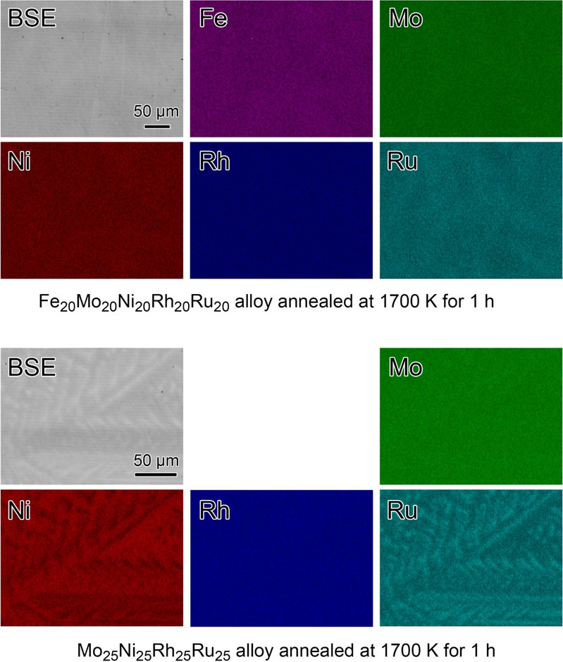
On the other hand, Fig. 3 (bottom) (Mo25Ni25Rh25Ru25 alloy at 1700 K for 1 h) demonstrates the presence of an apparent dendritic structure in the BSE image and Ni and Ru element mappings. The brightness and darkness of the element mappings of Ni and Ru indicate the compositional rich and poor regions, complementing each other. In contrast, the element mappings of Mo and Rh are almost uniform. Similar SEM and EDX spectroscopy results were obtained for the Mo35Ni15Rh15Ru35 alloy annealed at 1700 K for 1 h (not shown here). Probably, the dendritic structure of the Mo25Ni25Rh25Ru25 alloy was formed in the as-prepared sample during the solidification from the melt. It remained even at the annealing temperature as high as 1700 K. The comparison of the SEM and EDX spectroscopy results of the Fe20Mo20Ni20Rh20Ru20 and Mo25Ni25Rh25Ru25 alloys indicates that the inclusion of Fe in the Mo–Ni–Rh–Ru system prevented dendritic structure growth.
The experimental results shown in Figs. 1–3 indicate that the (b) Fe14Mo35Ni15Rh15Ru21 and (d) Fe20Mo20Ni20Rh20Ru20 alloys annealed at 1700 K for 1 h were formed in a HEA with a single hcp structure. The lattice constants of the (b) Fe14Mo35Ni15Rh15Ru21 alloy were evaluated to be a = 0.269 nm, c = 0.432 nm, and c/a = 1.606, whereas those of the (d) Fe20Mo20Ni20Rh20Ru20 alloy were a = 0.266 nm, c = 0.427 nm, and c/a = 1.605 (from Fig. 2). These values deviate from those of pure Ru (a = 0.2706 nm, c = 0.4282 nm, and c/a = 1.5824) and Fe50Ru50 (a = 0.269 nm, c = 0.427 nm, and c/a = 1.57).19,32) Figure 2 shows that the corresponding reflection peaks, such as the ($10\bar{1}1$) peak around 2θ = 43.8–44.7° in each alloy, tend to shift to larger 2θ angles in the (a–d) alloys in this order. This tendency indicates the decreases in lattice constants in this order.
Figure 4 shows Smix/R against T, where the solid and broken lines indicate Smix/R for the single hcp and other structures, respectively. The plots of Smix/R for the (a) Mo35Ni15Rh15Ru35 and (c) Mo25Ni25Rh25Ru25 alloys are also compared. Furthermore, Smix/R for the other structures was calculated as a reference, although the SER was set to be the hcp structure even for other structures in the calculation of Smix. For example, Smix/R of the liquid phase at 3000 K in a liquid phase contains the melting entropy from a solid to a liquid due to SER = hcp. Figure 4 indicates that Smix/R of every single hcp structure drawn with a thick solid line is constant over the temperature range, including 1700 K. The evaluated values of Smix/R were 1.386, 1.746, 1.503, and 1.8460 for the (a) Mo35Ni15Rh15Ru35, (b) Fe14Mo35Ni15Rh15Ru21, (c) Mo25Ni25Rh25Ru25, and (d) Fe20Mo20Ni20Rh20Ru20 alloys, respectively. On the other hand, the values of Sconfig/R at a single hcp structure were calculated to be 1.304, 1.540, 1.386, and 1.609 for the (a) Mo35Ni15Rh15Ru35, (b) Fe14Mo35Ni15Rh15Ru21, (c) Mo25Ni25Rh25Ru25, and (d) Fe20Mo20Ni20Rh20Ru20 alloys, while the resultant values of Smix/Sconfig were 1.06, 1.13, 1.08, and 1.14, respectively. Thus, Smix/Sconfig tends to increase with the magnitude of Sconfig in the order of (a), (c), (b), and (d), denoted by the upward arrow in Fig. 4. This tendency suggests that EE-HEAs exhibit higher Smix/Sconfig values than those of non-EE-HEAs.

Consequently, according to Figs. 1–4, the (b) Fe14Mo35Ni15Rh15Ru21 and (d) Fe20Mo20Ni20Rh20Ru20 alloys are regarded as single-phase UHMixEAs15) due to the definition of Smix/Sconfig > 1. Among the four alloys, (d) Fe20Mo20Ni20Rh20Ru20 as well as (b) Fe14Mo35Ni15Rh15Ru21 exhibited the highest Smix/Sconfig > 1.1, which has been obtained only for an Al6Co27Cr34Fe19V14 UHMixEA15) (Smix/Sconfig = 1.15 at 1600 K). Furthermore, the Fe20Mo20Ni20Rh20Ru20 UHMixEA was significant in the first quinary EE-hcp-HEAs consisting of only TMs, fabricated by solidification from a melt.
4. Discussion
The following single-phase alloys with abbreviated names in parentheses were considered in the analysis: hcp-Fe20Mo20Ni20Rh20Ru20 UHMixEA (Fe20 alloy) from this study, three types of UHMixEAs15) of bcc-Al6Co27Cr34Fe19V14 (Al6 alloy), hcp-Co20Cr20Fe20Ru30V10 (Ru30 alloy), and fcc-Co20Cr20Fe20Ni30V10 (Ni30 alloy), two representative HEAs of fcc-Co20Cr20Fe20Mn20Ni20 (Cantor alloy)2) and bcc-Mo20Nb20Ta20V20W203) (Senkov alloy), and hcp-Co25Fe25Rh25Ru259) HEA (Co25 alloy) for comparison. In calculating Smix/Sconfig–T diagram in Fig. 5(a), SER, as described in item (i) in Subsection 2.2, was set to be each intrinsic structure (bcc, fcc, or hcp) of the above alloys.

As shown in Fig. 5(a), an increase in Smix/Sconfig with the decrease in T was observed for the Co-containing alloys of Al6, Co25, Ru30, Ni30, and Cantor-alloys in a single stable phase drawn with thick curves. Each plot in Fig. 5(a) includes a bending point at the Curie temperature (Tc) of Co (Tc = 1450 K for bcc and 1396 K for fcc and hcp structures) where the Tc values correspond to those in Fig. 5(b).15) At T < Tc, an increase in Smix/Sconfig can occur due to a difference in SER.14) The increase in Smix/Sconfig occurred because the states of the alloy of interest and constituent elements are para- and ferromagnetic, respectively. An increase in Smix/Sconfig occurred HEAs containing 3d TMs since most of the HEAs are paramagnetic alloys.
In contrast, Co-free alloys (Fe20- and Senkov alloys) exhibit constant Smix/Sconfig in Fig. 5(a). For example, the bcc-Mo20Nb20Ta20V20W203) (Senkov alloy) exhibits Smix/Sconfig = 0.872 < 1. This tendency of Smix/Sconfig < 1 has been reported:14) most of the bcc-HEAs represented by EE-bcc-HEAs exhibit Smix/Sconfig < 1. Similarly, the hcp-Fe20Mo20Ni20Rh20Ru20 UHMixEA (Fe20 alloy) has a high constant value of Smix/Sconfig ∼ 1.14. The constant Smix/Sconfig values against T were due to the Co-free structure and absence of a bending point around Tc of Co.
Figure 5(a) shows a peculiar behavior of Smix/Sconfig of the Al6 alloy in a metastable state (thin curve). Another bending point is observed at the thin curve at T = 1043 K, which corresponds to Tc in Fig. 5(c) for α-Fe (bcc). An important aspect is that the magnetic transition of Fe occurs only for the bcc structure (no magnetic transitions occur for the hcp and fcc structures). The other alloys (hcp-Fe20, hcp-Co25, fcc-Cantor-, hcp-Ru30, and fcc-Ni30 alloys) confirmed the absence of bending point for Smix/Sconfig around Tc = 1043 K for bcc-Fe, although these alloys contain Fe element.
A similar increase in Smix/Sconfig is observed for the Cantor and Ni30 alloys with metastable structures in Fig. 5(a). The Cantor and Ni30 alloys exhibit a bending point at Tc(Ni, fcc) ∼ 630 K. Furthermore, the Cantor alloy exhibits another bending point around T = 540 K, denoted by the down arrow. T ∼ 540 K corresponds to Ttrans (Mn, hcp and fcc), as shown in Fig. 5(e). Presumably, a magnetic transition of the fcc-Mn (γ-Mn) antiferromagnetism occurs at Ttrans ∼ 540 K. Similarly, Cr with hcp and fcc structures exhibits Ttrans ∼ 360 K (the data are not shown in this paper). Hence, the Smix/Sconfig curve of the fcc-Cantor alloy in the metastable state exhibits three bending points resulting from magnetic transitions of Co, Ni, and Mn.
In general, the values of Smix/Sconfig of Co-containing alloys were affected by the Co contents. For example, the highest value of Smix/Sconfig = 1.25 was observed for the Co25 alloy9) at T = 830 K. Other alloys containing 20 at% Co (Ru30, Cantor, and Ni30 alloys) exhibit almost the same values of Smix/Sconfig. At T ∼ 1600, the magnitudes of Smix/Sconfig of the 20-at%-Co alloys (Ni30, Ru30, and Cantor alloys), Co25 alloy, and Al6 alloy (27 at% Co) increase in this order, which indicates the influence of the Co content on the magnitude of Smix/Sconfig. The effect of magnetism on S, which should be included in the second term on eq. (2) as Sexcess, can be dealt with Inden model33) and Hillert–Jarl modifications.34) However, a compositional dependence of the effect of magnetism on S is considerably complicated and beyond the reach of the purpose of the present study. Hence, further discussion of the effect of magnetism on S will not proceed in the present paper. The authors think that only the values of Tc of the constituent elements in Figs. 5(b)–(e) are worth noting in that Tc’s affect Smix of the paramagnetic single-phase UHMixEAs in both equilibrium and metastable states.
Figure 5 and eq. (2) indicate that Smix of HEAs and UHMixEAs can be compared consistently at T > Tc(trans), such as T = 1600 K, as paramagnetic alloys where Tc = 1450 K for bcc-Co and 1396 K for fcc- and hcp-Co. The effect of the ferromagnetism is included in the second term on the right side of eq. (2) for paramagnetic alloys containing 3d TMs (Cr and Mn, Co, Fe, and Ni). In contrast, it is excluded for a couple of ferromagnetic single-phase HEAs,35) such as fcc-CoFeMnNi and bcc-AlCoFeMnNi with Tc of 125 and 325 K, respectively. The inclusion of Al could contribute to the formation of a ferromagnetic bcc-HEA (bcc-UHMixEA). However, a decrease in Smix/R due to chemical ordering (B2 phase) has been reported.15) Besides, candidates for ferromagnetic HEAs might be high-entropy bulk metallic glasses (HE-BMGs), such as Fe25Co25Ni25(B, Si)25.36) However, HE-BMGs have formed in a nonequilibrium state, with neither bcc structure nor thermodynamically stable phase. Furthermore, we should devote attention to the inclusion of B in the HE-BMGs for calculation of Sconfig and Smix because B is not a substitutional but an interstitial element. A CoCrFeNiGa HEA35) is a ferromagnet alloy with Tc = 703 K; however, it is a mixture of bcc and fcc structures. Hence, it is worth searching for unprecedented single-phase ferromagnetic bcc-UHMixEAs with Fe as a constituent element, for further development of HEAs.
5. Conclusions
Mo35Ni15Rh15Ru35, Fe14Mo35Ni15Rh15Ru21, Mo25Ni25Rh25Ru25, and Fe20Mo20Ni20Rh20Ru20 alloys were analyzed to clarify the formation of HEAs with a single hcp structure. XRD, SEM, and EDX spectroscopy revealed that the Fe14Mo35Ni15Rh15Ru21 alloy annealed at 1700 K for 1 h formed a single hcp structure, together with the Fe20Mo20Ni20Rh20Ru20 alloy. The Mo35Ni15Rh15Ru35 and Mo25Ni25Rh25Ru25 alloys annealed at 1700 K for 1 h mainly formed into hcp structures but these alloys included a dendritic structure. The comparison of the SEM and EDX spectroscopy results between the Fe20Mo20Ni20Rh20Ru20 and Mo25Ni25Rh25Ru25 alloys indicated that the addition of Fe in the Mo–Ni–Rh–Ru system contributes to the suppression of the nucleation and growth of a dendritic structure. The hcp-Fe20Mo20Ni20Rh20Ru20 HEA annealed at 1700 K for 1 h exhibited Smix/R of 1.846, 14% higher than Sconfig/R = ln 5, indicating that it is UHMixEA. hcp-Fe20Mo20Ni20Rh20Ru20 is the first quinary EE-hcp-UHMixEA, experimentally confirmed, comprising only TMs, fabricated by solidification from a melt. A precise calculation of Smix in the design of HEAs led to two hcp-UHMixEAs of Fe20Mo20Ni20Rh20Ru20 and Fe14Mo35Ni15Rh15Ru21. A thermodynamic analysis for the referential Co-containing HEAs revealed that the increase in Smix/Sconfig mainly occurs due to magnetic transition at the Curie temperature of Co or below.
Acknowledgment
Japan Society for the Promotion of Science KAKENHI supported this study (principally through grant JP22H01816 and partially through grants JP18H05452 and JP21H00146).
REFERENCES
- 1) J.W. Yeh, S.K. Chen, S.J. Lin, J.Y. Gan, T.S. Chin, T.T. Shun, C.H. Tsau and S.Y. Chang: Adv. Eng. Mater. 6 (2004) 299–303. doi:10.1002/adem.200300567
- 2) B. Cantor, I.T.H. Chang, P. Knight and A.J.B. Vincent: Mater. Sci. Eng. A 375–377 (2004) 213–218. doi:10.1016/j.msea.2003.10.257
- 3) O.N. Senkov, G.B. Wilks, D.B. Miracle, C.P. Chuang and P.K. Liaw: Intermetallics 18 (2010) 1758–1765. doi:10.1016/j.intermet.2010.05.014
- 4) F. Otto, Y. Yang, H. Bei and E.P. George: Acta Mater. 61 (2013) 2628–2638. doi:10.1016/j.actamat.2013.01.042
- 5) A. Takeuchi, K. Amiya, T. Wada, K. Yubuta and W. Zhang: JOM 66 (2014) 1984–1992. doi:10.1007/s11837-014-1085-x
- 6) M. Feuerbacher, M. Heidelmann and C. Thomas: Mater. Res. Lett. 3 (2015) 1–6. doi:10.1080/21663831.2014.951493
- 7) M.C. Gao: High-Entropy Alloys: Fundamentals and Applications, (Springer, 2016) p. xiii.
- 8) R.X. Li, J.W. Qiao, P.K. Liaw and Y. Zhang: Acta Metall. Sin. (Engl. Lett.) 33 (2020) 1033–1045. doi:10.1007/s40195-020-01045-9
- 9) M.C. Gao, B. Zhang, S.M. Guo, J.W. Qiao and J.A. Hawk: Metall. Mater. Trans. A 47 (2016) 3322–3332. doi:10.1007/s11661-015-3091-1
- 10) K.V. Yusenko, S. Riva, P.A. Carvalho, M.V. Yusenko, S. Arnaboldi, A.S. Sulthikh, M. Hanfland and S.A. Gromilov: Scr. Mater. 138 (2017) 22–27. doi:10.1016/j.scriptamat.2017.05.022
- 11) C.L. Tracy, S. Park, D.R. Rittman, S.J. Zinkle, H. Bei, M. Lang, R.C. Ewing and W.L. Mao: Nat. Commun. 8 (2017) 15634. doi:10.1038/ncomms15634
- 12) J. Moon, Y.S. Qi, E. Tabachnikova, Y. Estrin, W.M. Choi, S.H. Joo, B.J. Lee, A. Podolskiy, M. Tikhonovsky and H.S. Kim: Mater. Lett. 202 (2017) 86–88. doi:10.1016/j.matlet.2017.05.065
- 13) L. Kaufman and H. Bernstein: Computer Calculation of Phase Diagrams with Special Reference to Refractory Metals, (Academic Press, 1970) p. 334.
- 14) A. Takeuchi: Mater. Trans. 61 (2020) 1717–1726. doi:10.2320/matertrans.MT-M2020141
- 15) A. Takeuchi, T. Wada, T. Nagase and K. Amiya: Mater. Trans. 63 (2022) 835–844. doi:10.2320/matertrans.MT-M2022004
- 16) B. Liu, J.F. Wu, Y.W. Cui, Q.Q. Zhu, G.R. Xiao, S.Q. Wu, G.H. Cao and Z. Ren: Scr. Mater. 182 (2020) 109–113. doi:10.1016/j.scriptamat.2020.03.004
- 17) “SSOL7: SGTE Solutions Database”, https://www.engineering-eye.com/THERMOCALC/features/pdf/SSOL7_extended_info.pdf, accessed October 9, 2022.
- 18) “TCS High Entropy Alloys Database (TCHEA5)”, https://docplayer.net/217281626-Tcs-high-entropy-alloys-database-tchea5.html, accessed October 9, 2022.
- 19) Pearson’s Crystal Data: Crystal Structure Database for Inorganic Compounds (on CD-ROM), (ASM International, Materials Park, OH, U.S.A., 2011).
- 20) B. Sundman, B. Jansson and J.O. Andersson: Calphad 9 (1985) 153–190. doi:10.1016/0364-5916(85)90021-5
- 21) Binary Alloy Phase Diagrams, Second Edition, Plus Updates (on CD-ROM), (ASM International, Materials Park, OH, U.S.A., 2011).
- 22) A. Takeuchi, T. Wada and H. Kato: Mater. Trans. 60 (2019) 1666–1673. doi:10.2320/matertrans.M2019037
- 23) A. Takeuchi and T. Wada: Mater. Trans. 63 (2022) 7–15. doi:10.2320/matertrans.MT-M2021150
- 24) S. Guo, C. Ng, J. Lu and C.T. Liu: J. Appl. Phys. 109 (2011) 103505. doi:10.1063/1.3587228
- 25) A. Takeuchi and A. Inoue: Mater. Trans. 46 (2005) 2817–2829. doi:10.2320/matertrans.46.2817
- 26) F.R. de Boer, R. Boom, W.C.M. Mattens, A.R. Miedema and A.K. Nissen: Cohesion in Metals: Transition Metal Alloys, (North Holland Physics Publishing, a division of Elsevier Science Publishers B.V., The Netherlands, 1988) p. 758.
- 27) H. Bakker: Enthalpies in Alloys, (Trans Tech Publications Ltd., Zuerich, Switzerland, 1998).
- 28) Y. Zhang, Y.J. Zhou, J.P. Lin, G.L. Chen and P.K. Liaw: Adv. Eng. Mater. 10 (2008) 534–538. doi:10.1002/adem.200700240
- 29) A.R. Miedema and A.K. Niessen: Calphad 7 (1983) 27–36. doi:10.1016/0364-5916(83)90027-5
- 30) A. Takeuchi, T. Wada and H. Kato: Mater. Trans. 60 (2019) 2267–2276. doi:10.2320/matertrans.MT-M2019212
- 31) “Thermo-Calc Software”, https://thermocalc.com/, accessed December 8, 2021.
- 32) S.B. Qadri, T.M. Keller, M. Laskoski, C.A. Little, P. Lubitz, M.S. Osofsky and H.R. Khan: Appl. Phys. A 86 (2007) 391–394. doi:10.1007/s00339-006-3788-5
- 33) G. Inden: Z. Metallk. 66 (1975) 577–582.
- 34) M. Hillert and M. Jarl: Calphad 2 (1978) 227–238. doi:10.1016/0364-5916(78)90011-1
- 35) S.M. Na, J.H. Yoo, P.K. Lambert and N.J. Jones: AIP Adv. 8 (2018) 056412. doi:10.1063/1.5007073
- 36) T.L. Qi, Y.H. Li, A. Takeuchi, G.Q. Xie, H.T. Miao and W. Zhang: Intermetallics 66 (2015) 8–12. doi:10.1016/j.intermet.2015.06.015
