Abstract
X-ray fluorescence holography was applied to dilute Mg99.2Zn0.2Y0.6 alloy annealed at 520°C for 5 h to obtain atomic images around Zn atom. In spite of the extremely low concentration of the solute-element, clear hologram patterns were obtained. The reconstructed atomic images revealed that the Zn atom in this annealed Mg99.2Zn0.2Y0.6 alloy mainly occupy the hcp Mg site. This finding is consistent with the transmission electron microscope image, where fcc-type stacking faults are hardly observed. These results are in contrast to the previous report that Zn and Y form short-range-ordered solute clusters at the fcc-type stacking fault in Mg–Zn–Y alloy. The effect of heat treatment on the atomic arrangement of solute-elements in this dilute alloy is discussed in relation to the previously reported mechanical properties.
1. Introduction
A series of Mg alloys containing a few atomic percent of transition metal (TM) and rare-earth (RE) has been gathering much attention because of its excellent mechanical properties, such as very large tensile yield strength of ∼600 MPa.1–3) Furthermore, these alloys exhibit a curious atomic-level structure, the so-called synchronized long period stacking ordered (LPSO) structure,4–15) where the solute TM and RE elements are aggregated at the periodically inserted fcc-type stacking faults. According to an atomic-resolution high-angle annular dark field scanning transmission electron microscope (HAADF-STEM) observation of Mg–Zn–Y alloy,8) L12-type Zn6Y8 clusters are formed within these solute-enriched stacking faults (SESFs). The formation of such short-range-ordered (SRO) RE-TM clusters and the SESFs in this series of Mg alloys have been discussed in relation to the superior mechanical properties.
Recently, Hagihara et al. have demonstrated that the yield stress of Mg–Zn–Y alloy is significantly enhanced even in the case of dilute concentrations of solute-elements.16,17) They synthesized Mg99.2Zn0.2Y0.6 single crystal and revealed that its yield stress is comparable to that of the high-concentration Mg85Zn6Y9 alloy. This finding is important to develop even lighter structural materials and reduce the cost of REs. However, the detailed arrangement of the solute-elements in this dilute alloy has not been clarified. This is particularly because LPSO phase is not formed in the Mg99.2Zn0.2Y0.6 alloy, which makes it difficult to observe clear TEM images. Instead, this dilute alloy possesses sparsely distributed SESFs, which is called LPSO nanoplate.16,17) Furthermore, when this alloy is annealed at 520°C for 5 h, the number of LPSO nanoplates is drastically decreased together with the lowering of the yield strength.9) Whereas a cluster-like arrangement of the solute-elements within the LPSO nanoplate was observed in the as-grown sample,16) atomic arrangement of solute-elements in the annealed sample is less understood because of the small number of the LPSO nanoplates. Therefore, it is crucial to investigate the arrangement of the solute-element especially in the annealed sample, in order to bridge an atomic-level structure and the macroscopic mechanical properties of this dilute alloy.
X-ray fluorescence holography (XFH) is a promising method to elucidate the arrangement of the solute-elements in Mg–TM–RE alloy. XFH can visualize three-dimensional atomic arrangement around a specific element,18–20) and has been applied to various structural and functional materials,21–30) including Mg85Zn6Y9 and Mg75Zn10Y15 alloys.31,32) In particular, XFH is applicable to dilute systems,33) and thus local structures around solute-elements in dilute Mg99.2Zn0.2Y0.6 alloy are expected to be clarified by this technique.
In this paper we present atomic images around Zn atom in Mg99.2Zn0.2Y0.6 alloy annealed at 520°C for 5 h obtained by XFH measurements. Even though the concentration of Zn is extremely low (<1 at%), high-quality Zn-Kα holograms are obtained. Reconstructed atomic images around Zn show that most of the Zn atoms are located at hcp Mg site and not contained in SRO solute clusters, unlike the high-concentration alloys, such as Mg75Zn10Y15. This finding is consistent with the STEM images, where the SESFs and fcc-type stacking faults are hardly observed. These results are discussed in comparison with previously reported mechanical properties.
2. Experimental Procedure and Data Processing
2.1 Materials
A master ingot having a composition of Mg99.2Zn0.2Y0.6 was obtained by induction melting in a carbon crucible. Directionally solidified (DS) sample was prepared by Bridgeman technique (Nissin Giken NEV-DS2) in an Ar-gas atmosphere. Here, the growth rate was set to 5.0 mm h−1, and the temperature gradient in directional solidification was set to be ∼70°C mm−1. The size of obtained single crystal was φ12 mm in diameter and ∼100 mm in length. The chemical composition of the grown single crystal was measured by inductively coupled plasma (ICP) analysis to be Mg–0.26 at%Zn–0.76 at%Y. The obtained DS-grown specimen was annealed at 520°C for 5 h under an Ar atmosphere, and then quenched by water. The details of the sample preparation are described in Refs. 16 and 17).
Figure 1 shows Laue pattern of the Mg99.2Zn0.2Y0.6 single crystal taken by the imaging-plate-type back-reflection Laue camera (X-ray Science IPX-YGR). Clear spots were observed, which assures a good quality of the sample. Also, it is confirmed that the sample was cut along the $(11\bar{2}0)$ plane.
2.2 Transmission electron microscope observation
Bright field TEM and HAADF-STEM images were obtained using a conventional TEM (JEOL JEM-2010HC) operated at 200 kV and an aberration-corrected STEM (JEOL JEM-ARM200F) operated at 200 kV with a convergence semi-angle of 22 mrad, respectively. For HAADF-STEM imaging, the annular detector was set to collect the electrons scattered at angles higher than 90 mrad. Thin foils of DS Mg99.2Zn0.2Y0.6 alloy annealed at 520°C for 5 h for TEM observations were prepared by mechanical polishing and standard Ar-ion milling.
2.3 X-ray fluorescence holography experiment
XFH experiments were performed at BL39XU in the SPring-8, Japan. The Zn-Kα fluorescent X-rays (8.64 keV) from Mg99.2Zn0.2Y0.6 sample were analyzed by the toroidally-bend graphite analyzer crystal34) to focus the fluorescent X-rays on the position of avalanche photo-diode detector. The incident, θ, and azimuthal, φ, angles were moved in the ranges of 0° ≤ θ ≤ 75° and 0° ≤ ϕ ≤ 360° in steps of 1° and 0.25°, respectively. The energies of the incident X-rays were set from 10.0 keV to 12.00 keV in steps of 0.25 keV, which are above the Zn K-edge of 9.66 keV, and totally 9 holograms were recorded. The measurements were performed at room temperature. The details of the experimental setup are explained in Ref. 18).
2.4 Data processing
Figure 2(a) shows the obtained Zn-Kα hologram recorded at the incident X-ray energy of 10.0 keV. We can confirm a two-fold symmetric pattern of the hologram with respect to the $[11\bar{2}0]$ axis, which corresponds to the Laue picture shown in Fig. 1. In the analysis, the holograms were rotated as displayed in Fig. 2(b) to apply six-fold-symmetric operation with respect to the [0001] axis, which can extend the covering area of the hologram and enhance the statistical accuracy as well. Here, we also applied two-fold-symmetric operation with respect $[\bar{1}2\bar{1}0]$ and $[10\bar{1}0]$ axes, and mirror-symmetric operation with respect to $(\bar{1}2\bar{1}0)$ and $(10\bar{1}0)$ planes to cover the sphere. After applying these operations to all 9 holograms taken at the different energies, atomic images were reconstructed by the Barton’s algorithm.35) The data processing was performed by the dedicated software “3D-Air-Image”.36)
2.5 Calculation
For the comparison with the experimentally obtained atomic image, we also calculated the hologram of pure Mg to reconstruct atomic images. We generated a cluster of hcp Mg with a radius of 50 Å, and its holograms were calculated at the same incident X-ray energies as the experiment. Here, the equation described in Refs. 18–20) was used. Then, we cut out a part of the hologram spheres according to the experimentally recorded area of 0° ≤ θ ≤ 75° and 0° ≤ ϕ ≤ 360°. The symmetric operations were applied to these holograms in the same manner as described in subsection 2.3. From the obtained holograms, atomic images were reconstructed by the Barton’s algorithm.35) The calculations were also done using “3D-Air-Image”.36)
3. Results and Discussions
Figure 3(a) shows the bright field TEM image obtained from the present Mg99.2Zn0.2Y0.6 sample annealed at 520°C for 5 h. Here, we can not observe any aggregation of solute elements, which has been observed in the as-grown Mg99.2Zn0.2Y0.6 sample.16) Furthermore, no streak was observed in the electron diffraction pattern (inset of Fig. 3(a)). The absence of such an aggregation is also confirmed in the HAADF-STEM image in the same region (Fig. 3(b)). Note that the diagonal lines crossing through these images are caused by the variation in the sample thickness induced by the ion milling process. Therefore, it is indicated that almost all SESFs disappear after the annealing at 520°C for 5 h. Because of the absence of the SESFs, it is difficult to discuss the detailed arrangement of solute-elements from these images.

Figure 4(a) shows the Zn-Kα hologram of Mg99.2Zn0.2Y0.6 single crystal recorded at the incident X-ray energy of 10 keV obtained by the procedure described in Sect. 2. Here, we can confirm that the hologram covers almost all the sphere. Furthermore, clear standing wave lines are observed even though the concentration of Zn in the sample is very low, which assures that the XFH measurements have been successfully performed. Also, the pattern of the standing wave lines agrees well with that of the calculated hologram (Fig. 4(b)) obtained by the hcp Mg. This observation confirms that the matrix crystal structure of Mg99.2Zn0.2Y0.6 is the hcp structure. Owing to the limited size of the cluster in the calculation, the standing wave lines in the calculated hologram are broader in comparison with the experimental hologram.
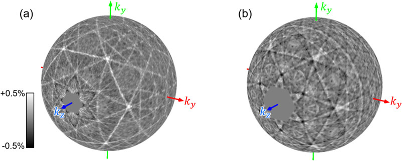
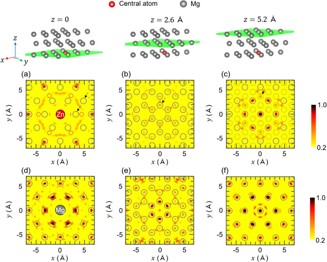
Figure 5 shows the reconstructed atomic images obtained by the XFH experiment for Mg99.2Zn0.2Y0.6 alloy ((a)∼(c)) and by the calculation for pure Mg ((d)∼(f)). Here, we reconstructed three ab planes on z = 0 ((a) and (d)), 2.6 Å ((b) and (e)), and 5.2 Å ((c) and (f)), which are schematically indicated in the upper part of Fig. 5. The solid circles in (a)∼(f) indicate the ideal positions of Mg atoms around the hcp Mg site. It is observed that atomic images appear within most of these circles and the overall agreement between experimental and calculated results are good, which clearly shows that Zn atoms mainly substitute the hcp Mg site in the present Mg99.2Zn0.2Y0.6 sample annealed at 520°C for 5 h.

On the other hand, the atomic images are not observed at the solid circles indicated by arrows in Fig. 5(a). It has been reported that positional fluctuation of atoms decreases the intensity of the atomic images.25,27,32,37–39) Therefore, the absence of the atomic image at the positions indicated by arrows shows that the positions of the corresponding Mg atoms around Zn are fluctuated. This behavior is attributable to the smaller atomic radius of Zn (1.34 Å) than that of Mg (1.60 Å), which produces a space for Mg atoms to move. The effect of the smaller atomic radius of Zn is also observed for the atomic image on z = 2.6 Å, i.e., the ratio of the atomic image intensity indicated by the arrow to the other atomic image intensities in Fig. 5(b) is weaker than that in the calculated result (Fig. 5(e)).
It has often been observed that solute-elements aggregate at the fcc-type stacking fault in the hcp Mg matrix in Mg-TM-RE alloys even in the region where the LPSO phase is not formed.40–42) However, few Zn atoms in the present annealed Mg99.2Zn0.2Y0.6 alloy are considered to be located at the fcc-type stacking fault, which can be understood from the atomic image on z = 5.2 Å (Fig. 5(c)). Since the stacking order of the hcp structure is ABABABA…, the expected atomic position on the plane at z = 5.2 Å is the same as those at z = 0 (solid circles). On the other hand, the stacking order in the fcc structure is ABCABCAB…, and thus atomic images on the planes at z = 5.2 Å should appear at the positions indicated by thin dotted circles in Fig. 5(c). Since clear atomic images are observed within solid circles in Fig. 5(c), most of the Zn atoms occupy the hcp Mg site. The weak atomic images within the dotted circles indicated by arrow in Fig. 5(c) are possibly originating from the Zn atoms in the fcc-type stacking fault, but obviously their contributions are minor. This result is consistent with the TEM observations (Fig. 3) that the SESFs are not present in Mg99.2Zn0.2Y0.6 sample annealed at 520°C for 5 h.
The dashed circles in Fig. 5(a) correspond to the intra-cluster positions of Zn atoms contained in the L12-type Zn6Y8 cluster,8) where we can not observe atomic images. This result is in clear contrast to the atomic image around Zn in Mg75Zn10Y15 alloy annealed at 500°C for 24 h, where atomic images appear only at the positions corresponding to the intra-cluster Zn atoms.32) Therefore, it is revealed that the formation of the Zn–Y SRO clusters is not dominant in the present annealed Mg99.2Zn0.2Y0.6 sample although various-types of SRO solute clusters have been found in Mg-TM-RE ternary systems by TEM observations in combination with the first-principles calculations, such as ZnGd3 cluster in Mg97Zn1Gd2 alloy40,41) and Co3Y5 cluster in Mg97Co1Y2 alloy.43,44)
Previous TEM observation of Mg99.2Zn0.2Y0.6 alloy16) reported that the number of the LPSO nanoplates is decreased by the annealing at 520°C for 5 h, which was attributed to the enhanced solubility of the Zn atoms at the present high-annealing temperature of 520°C and the resulting instability of the LPSO nanoplate microstructure. This behavior is consistent with the present observation that the most of the Zn atoms substitute the hcp Mg site. Although TEM image also showed a strong aggregation of the solute elements in the annealed alloy to form thick solute-enriched layer along the ab plane, only a small part of solute-elements is contained in this thick layer.16) Therefore, effect of such an aggregation on the atomic images is considered to be negligible.
According to Ref. 16), the yield stress of the Mg99.2Zn0.2Y0.6 alloy is strongly dependent on the heat treatment. Whereas the yield stress of the as-grown DS Mg99.2Zn0.2Y0.6 alloy shows about 170 MPa in the $[11\bar{2}0]$ orientation, it is decreased to ∼110 MPa by the annealing at 520°C for 5 h, corresponding to the annealing conditions of the present sample. The absence of the atomic image originating from the SRO solute clusters in Fig. 5 can be related to this lower yield stress after the heat treatment. In order to clarify the relation between the formation of the SRO cluster and the mechanical properties, it is important to systematically investigate the local structures around the solute-elements at various stages of heat treatment, which is our future work.
4. Conclusion
We have performed X-ray fluorescence holography experiment for Mg99.2Zn0.2Y0.6 alloy annealed at 520°C for 5 h to obtain Zn-Kα X-ray fluorescence holograms. In spite of the dilute concentration of the Zn atoms, clear standing wave lines were observed in the holograms, which shows that high-quality data have been obtained. The reconstructed atomic image around Zn evidences that most of the Zn atoms occupy the hcp Mg site, which is consistent with the TEM observations that SESFs are not significantly formed. No indications of the formation of SRO clusters were confirmed in the present atomic image, which is in contrast to the higher concentration alloys, such as Mg75Zn10Y15. These observations can be attributed to the enhanced solubility of the Zn atoms and the decrease in the LPSO nanoplate microstructure by the heat treatment, which also causes a lowering of the yield stress. As a future work, we will investigate the local structure around solute-elements in dilute Mg–Zn–Y alloy at various stages of the heat treatment, which lead us to clarify the correlation of the formation of the SRO clusters to the mechanical properties.
Acknowledgments
The authors are grateful to Prof. Michiaki Yamasaki for providing us the information of the detailed composition of the sample. This work was supported by the Japan Society for the Promotion of Science (JSPS) with Grants-in-Aid for Innovative Areas “Materials Science on Mille-Feuille Structure” (Nos. 19H05126, 21H00099, and 21H00092), Transformative Research Areas (A) “Hyper-Ordered Structures Science” (Nos. 21H05551, 20H05878, and 20H05881), Scientific Research (B) (No. 22H01774), and “Advanced Research Infrastructure for Materials and Nanotechnology (ARIM)” of the MEXT, Japan (JPMXP09A22UT0008). The XFH experiments were performed at BL39XU, BL13XU, and BL37XU of SPring-8 with the approval of the Japan Synchrotron Radiation Research Institute (JASRI), (Proposal Nos. 2022A1112, 2021B1480, 2021B1481, 2021A1328, 2021A1331, 2020A1355, 2019B1510).
REFERENCES
- 1) Y. Kawamura, K. Hayashi, A. Inoue and T. Masumoto: Mater. Trans. 42 (2001) 1172. doi:10.2320/matertrans.42.1172
- 2) Y. Kawamura and M. Yamasaki: Mater. Trans. 48 (2007) 2986. doi:10.2320/matertrans.MER2007142
- 3) K. Hagihara, A. Kinoshita, Y. Sugino, M. Yamasaki, Y. Kawamura, H.Y. Yasuda and Y. Umakoshi: Acta Mater. 58 (2010) 6282. doi:10.1016/j.actamat.2010.07.050
- 4) E. Abe, Y. Kawamura, K. Hayashi and A. Inoue: Acta Mater. 50 (2002) 3845. doi:10.1016/S1359-6454(02)00191-X
- 5) Y.M. Zhu, M. Weyland, A.J. Morton, K. Oh-ishi, K. Hono and J.F. Nie: Scr. Mater. 60 (2009) 980. doi:10.1016/j.scriptamat.2009.02.029
- 6) T. Itoi, T. Seimiya, Y. Kawamura and M. Hirohashi: Scr. Mater. 51 (2004) 107. doi:10.1016/j.scriptamat.2004.04.003
- 7) E. Abe, A. Ono, T. Itoi, M. Yamasaki and Y. Kawamura: Philos. Mag. Lett. 91 (2011) 690. doi:10.1080/09500839.2011.609149
- 8) D. Egusa and E. Abe: Acta Mater. 60 (2012) 166. doi:10.1016/j.actamat.2011.09.030
- 9) D. Egusa, M. Yamasaki, Y. Kawamura and E. Abe: Mater. Trans. 54 (2013) 698–702. doi:10.2320/matertrans.MI201216
- 10) M. Yamasaki, M. Matsushita, K. Hagihara, H. Izuno, E. Abe and Y. Kawamura: Scr. Mater. 78 (2014) 13–16. doi:10.1016/j.scriptamat.2014.01.013
- 11) K. Yamashita, T. Itoi, M. Yamasaki, Y. Kawamura and E. Abe: J. Alloy. Compd. 788 (2019) 277–282. doi:10.1016/j.jallcom.2019.02.219
- 12) D. Egusa, H. Somekawa and E. Abe: Mater. Trans. 61 (2020) 833–838. doi:10.2320/matertrans.MT-MM2019010
- 13) M. Itakura, M. Yamaguchi, D. Egusa and E. Abe: Acta Mater. 203 (2021) 116491. doi:10.1016/j.actamat.2020.116491
- 14) D. Egusa, K. Inoue, Y. Nagai and E. Abe: Mater. Charact. 177 (2021) 111153. doi:10.1016/j.matchar.2021.111153
- 15) K. Guan, D. Egusa and E. Abe: J. Magnesium Alloys 10 (2022) 1573–1580. doi:10.1016/j.jma.2021.11.007
- 16) K. Hagihara, R. Ueyama, M. Yamasaki, Y. Kawamura and T. Nakano: Acta Mater. 209 (2021) 116797. doi:10.1016/j.actamat.2021.116797
- 17) K. Hagihara, R. Ueyama, T. Tokunaga, M. Yamasaki, Y. Kawamura and T. Nakano: Mater. Res. Lett. 9 (2021) 467. doi:10.1080/21663831.2021.1974593
- 18) K. Hayashi, N. Happo, S. Hosokawa, W. Hu and T. Matsushita: J. Phys. Condens. Matter 24 (2012) 093201. doi:10.1088/0953-8984/24/9/093201
- 19) K. Hayashi and P. Korecki: J. Phys. Soc. Jpn. 87 (2018) 061003. doi:10.7566/JPSJ.87.061003
- 20) K. Kimura: J. Phys. Soc. Jpn. 91 (2022) 091005. doi:10.7566/JPSJ.91.091005
- 21) T. Yamamoto, K. Hayashi, N. Happo, S. Hosokawa and H. Tajiri: Acta Mater. 131 (2017) 534. doi:10.1016/j.actamat.2017.03.048
- 22) W. Hu, K. Hayashi, K. Ohwada, J. Chen, N. Happo, S. Hosokawa, M. Takahasi, A.A. Bokov and Z.-G. Ye: Phys. Rev. B 89 (2014) 140103(R). doi:10.1103/PhysRevB.89.140103
- 23) W. Hu, K. Hayashi, T. Fukumura, K. Akagi, M. Tsukada, N. Happo, S. Hosokawa, K. Ohwada, M. Takahasi, M. Suzuki and M. Kawasaki: Appl. Phys. Lett. 106 (2015) 222403. doi:10.1063/1.4921847
- 24) S. Hosokawa et al.: Phys. Rev. B 96 (2017) 214207. doi:10.1103/PhysRevB.96.214207
- 25) K. Kudo, S. Ioka, N. Happo, H. Ota, Y. Ebisu, K. Kimura, T. Hada, T. Kimura, H. Tajiri, S. Hosokawa, K. Hayashi and M. Nohara: J. Phys. Soc. Jpn. 88 (2019) 063704. doi:10.7566/JPSJ.88.063704
- 26) T. Fujiwara, A. Sasahara, N. Happo, K. Kimura, K. Hayashi and H. Onishi: Chem. Mater. 32 (2020) 1439. doi:10.1021/acs.chemmater.9b04094
- 27) K. Kimura, K. Yamamoto, K. Hayashi, S. Tsutsui, N. Happo, S. Yamazoe, H. Miyazaki, S. Nakagami, J.R. Stellhorn, S. Hosokawa, T. Matsushita, H. Tajiri, A.K.R. Ang and Y. Nishino: Phys. Rev. B 101 (2020) 024302. doi:10.1103/PhysRevB.101.024302
- 28) K. Kimura, D. Urushihara, Y.Y.R. Kondo, A.K.R. Ang, T. Asaka, N. Happo, T. Hagihara, T. Matsushita, H. Tajiri, H. Miyazaki, K. Ohara, M. Iwata and K. Hayashi: Phys. Rev. B 104 (2021) 144101. doi:10.1103/PhysRevB.104.144101
- 29) Y. Yamamoto, K. Kawamura, H. Sugimoto, A. Gadelmawla, K. Kimura, N. Happo, H. Tajiri, K.G. Webber, K. Kakimoto and K. Hayashi: Appl. Phys. Lett. 120 (2022) 052905. doi:10.1063/5.0076325
- 30) H. Kizaki, K. Hayashi, C. Lu, N. Happo, S. Hosokawa, S. Hidaka, S. Hayashi, M. Suzuki and N. Uchitomi: Phys. Rev. B 106 (2022) 064434. doi:10.1103/PhysRevB.106.064434
- 31) K. Kimura, K. Hayashi, K. Hagihara, H. Izuno, N. Happo, S. Hosokawa, M. Suzuki and H. Tajiri: Mater. Trans. 58 (2017) 539. doi:10.2320/matertrans.M2016459
- 32) T. Nishioka, Y. Yamamoto, K. Kimura, K. Hagihara, H. Izuno, N. Happo, S. Hosokawa, E. Abe, M. Suzuki, T. Matsushita and K. Hayashi: Materialia 3 (2018) 256. doi:10.1016/j.mtla.2018.09.002
- 33) Y. Yamamoto, K. Kimura, A. Gadelmawla, K. Kawamura, H. Sugimoto, D. Liu, Q. Li, Q. Yan, N.H. Khansur, N. Happo, K. Kakimoto, K.G. Webber and K. Hayashi: Phys. Status Solidi B 259 (2022) 2100609. doi:10.1002/pssb.202100609
- 34) T. Sekioka, K. Hayashi, E. Matsubara, Y. Takahashi, T. Hayashi, M. Terasawa, T. Mitamura, A. Iwase and O. Michikami: J. Synchrotron Radiat. 12 (2005) 530. doi:10.1107/S0909049505006497
- 35) J.J. Barton: Phys. Rev. Lett. 67 (1991) 3106. doi:10.1103/PhysRevLett.67.3106
- 36) https://osdn.jp/projects/tmcoca/releases/p14436.
- 37) S. Hosokawa, N. Happo and K. Hayashi: Phys. Rev. B 80 (2009) 134123. doi:10.1103/PhysRevB.80.134123
- 38) K. Hayashi, N. Uchitomi, K. Yamagami, A. Suzuki, H. Yoshizawa, J.T. Asubar, N. Happo and S. Hosokawa: J. Appl. Phys. 119 (2016) 125703. doi:10.1063/1.4945004
- 39) M. Kitaura, A.K.R. Ang, Y. Yamamoto, N. Happo, K. Kimura, K. Hayashi, S. Watanabe, Y. Yokota, Y. Ohashi, K. Kamada, A. Yoshikawa, H. Yamane and A. Ohnishi: Front. Mater. 9 (2022) 977371. doi:10.3389/fmats.2022.977371
- 40) D. Egusa, K. Kawaguchi and E. Abe: Front. Mater. 6 (2019) 266. doi:10.3389/fmats.2019.00266
- 41) D. Egusa, R. Manabe, T. Kawasaki, S. Harjo, S. Sato and E. Abe: Mater. Today Commun. 31 (2022) 103344. doi:10.1016/j.mtcomm.2022.103344
- 42) M. Egami, I. Ohnuma, M. Enoki, H. Ohtani and E. Abe: Mater. Des. 188 (2020) 108452. doi:10.1016/j.matdes.2019.108452
- 43) K. Guan, M. Egami, D. Egusa, H. Kimizuka, M. Yamasaki, Y. Kawamura and E. Abe: Scr. Mater. 207 (2022) 114282. doi:10.1016/j.scriptamat.2021.114282
- 44) M. Egami, I. Ohnuma, M. Enoki, H. Ohtani and E. Abe: Mater. Trans. 61 (2020) 839–848. doi:10.2320/matertrans.MT-MM2019009