Abstract
This study describes the basic capabilities of an “Explicit” kink model based on Field Theory of Multiscale Plasticity (FTMP), where the incompatibility tensor-incorporated additional degrees of freedom (DOFs), mediated by the Rank-1 connectivity-based projection direction with variable shear measure, directly drives the kink field evolutions in addition to the conventional slip mode. Not only inhomogeneous but realistic kink morphologies but also slightly improved energy releasing characteristics are shown to be reproduced. Furthermore, virtual double compression tests are performed on thus obtained kinked samples, demonstrating the kink strengthening that qualitatively agrees with experiments. Further enrichment of the model via the incompatibility-based DOFs introduced also in the slip model is shown to be able to simulate even more realistic kink morphologies and the attendant rotation angle distributions accurately.
1. Introduction
Kink formation/strengthening has been attracted immense attentions, in the context of MFS, especially in conjunction with the possibility for us to add a new one to the list of representative strengthening mechanisms for the first time in fifty years.1) Careful re-observations of micrographs against deformed materials has turned out that “kinking” is a ubiquitous phenomenon that may have non-negligible contributions to the mechanical behaviors, although it seems to have been overlooked so far simply because we did not show special interests in it. After the discovery of its importance by Kawamura and his colleagues in Mg–Zn–Y ternary alloys containing LPSO (long-period stacking ordered) phase, exhibiting excellent mechanical properties including high enough strength together with reasonable ductility,2,3) considerable number of studies have been started like pouring out of a broken dam.4–14) After two decades have passed since then, still many mysteries remain unsolved about the basic mechanisms. Particularly, it is surprising that no theory/simulation models have satisfactorily succeeded in reproducing “ridge kink” morphologies hitherto by crystal plasticity-based finite element simulations15,16) beyond mere a “buckling-like” modes that tends to follow “Hess & Ballet” mode17) at most that look far from real ones for such a long period of time, regardless of many approaches by excellent researchers worldwide. Some easy analysis even assumes kink-like structure beforehand, giving up their numerical reproductions from the start. Such an status quo strongly implies something critical is missing there in capturing the kinking processes, or else, simply inadequately off the mark, at least from theoretical/numerical points of view.
The authors have coped with the above situation based on Field Theory of Multiscale Plasticity (FTMP)18–27) by utilizing the incompatibility tensor-related additional underlying microscopic degrees of freedom ($\boldsymbol{\eta}$-DOF), already demonstrating to be able to reproduce “ridge kink” morphologies in the previous study25,26) quite easily. Furthermore, the discussions were extended to examine the associated energy releasing behavior in conjunction with AE (acoustic emission) measurement by Aizawa et al.28) that demonstrated specific nature such as “scale free” distribution in the AE energy-frequency plots and the associated specific return maps exhibiting fourth-quadrant concentration. It was, however, just the scratch toward further investigations, in the sense it assumed uniform shear measure throughout the sample for the Rank-1-based kink mode treatment as a primary step and, moreover, no mention in the strengthening in there.
This study addresses further improvements of the previous kink model25,26) by introducing variable shear measure for the Rank-1-based treatment,29) followed by examining afresh how to take the kink model into account in the FTMP-based FE (finite element) simulations. Discussions based on such new model include not only those about the morphological aspects and the AE characteristics, but also virtual double compression test30) targeting the strengthening brought about by “already developed” kink fields, i.e., “secondary” strengthening effect, based on which we examine to what extent the kinked regions are strengthened in an explicit manner. Regarding the morphological aspects, we further scrutinize in some detail by comparing with experimental observations, etc.
2. Theoretical Background
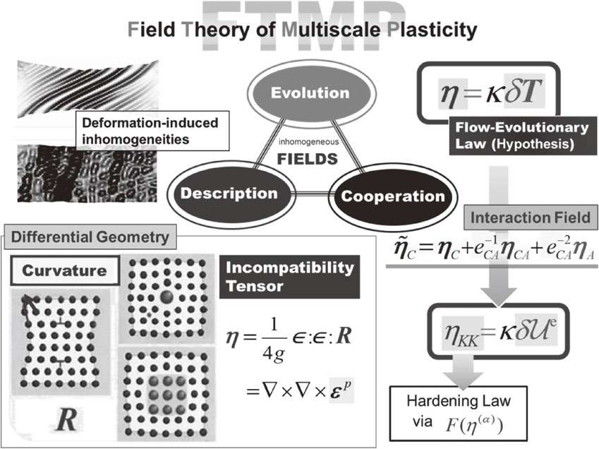
2.1 Brief overview of FTMP
Field theory of multiscale plasticity (FTMP)18–27) is a novel theoretical framework, aiming at rationally dealing with spatio-temporally deformation-induced evolving inhomogeneous fields in a comprehensive manner, by viewing them from three standpoints of (a) description, (b) evolution and (c) cooperation.24,27) The core concepts of FTMP are three-fold, as schematized in Fig. 1, i.e., (i) the extended incompatibility tensor to four-dimensional space-time, (ii) a working hypothesis called the flow-evolutionary law24,27) that states the organic interrelationship between the incompatibility tensor and the energy-momentum tensor fluctuation, i.e., ηij = κδTij and (iii) the interaction field formalism for the incompatibility tensor. The pure temporal component of the flow-evolutionary law yields the specific form that relates the incompatibility trace with elastic strain energy fluctuation $\eta_{KK} = \kappa \delta \mathcal{U}^{e}$ for static conditions. The 4D incompatibility tensor is defined as,
| \begin{equation}
\eta_{ij} = \in_{iklp} \in_{jmnp} \partial_{k}\partial_{m} \varepsilon_{\textit{ln}}^{p}
\end{equation}
| (1) |
where the indices run from 1 through 3 (space) and 4 (time). The incompatibility tensor is taken into account in the crystal plasticity-based finite element method (CP-FEM) via the incompatibility term to be introduced as the underlying microscopic degrees of freedom (
$\boldsymbol{\eta}$-µDOF) in the hardening law, given by,
| \begin{equation}
F(\eta_{\textit{proj}}^{(\alpha)}) = \mathop{\text{sgn}}\nolimits(\eta_{\textit{proj}}^{(\alpha)})\cdot k_\eta^{*}\left(\frac{l_{\textit{defect}}}{b}|\eta_{\textit{proj}}^{(\alpha)}| \right)^{1/2}
\end{equation}
| (2) |
where
$k_{\eta }^{*}$ represents a proportionality coefficient, introduced in the derivation process of
eq. (2), by assuming a linear relationship
31) between the cell size,
24) dcell ∝ (
QαβQαβ)
−1/2, and the mean spacing of the wall-constructing dislocations,
$\bar{l} = (l_{\textit{defect}}/b|\eta_{\textit{proj}}^{(\alpha )}|)^{ - 1/2}$ in the present context. The incompatibility field
$\eta_{\textit{proj}}^{(\alpha )} \equiv \Omega_{\textit{proj}\,ij}^{(\alpha )}\eta_{ij}$ expresses that are projected onto the prescribed slip systems for slip modes, whereas onto that associated with the Rank-1 connectivity
29) for the kink mode.
25,26) Here, the parameter
ldefect represents the characteristic (referential) length of the targeted defect field, e.g.,
ldefect =
b (magnitude of Burgers vector) for dislocation dipoles, or
ldefect = 1.0 µm for dislocation substructures like cells and deformation twinning.
24) For the kinking modes, we may assume
ldefect = 100 µm, as will be examined later on. In evaluating the strain gradient for obtaining the dislocation density/incompatibility tensor, we approximate an equation of hyperplane against the finite elements involved in a circular region specified by a radius
rGR (for gradient range) via the least square method, whose coefficient gives the gradient in each direction. Here, we choose
rGR = 3.0 µm throughout the study. The projection tensor
$\Omega_{\textit{proj}\,ij}^{(\alpha )}$ specifies the projection directions, e.g., the symmetric part of
$\Omega_{\textit{slip}\,ij}^{(\alpha )} = t_{i}^{(\alpha )}s_{j}^{(\alpha )} + s_{i}^{(\alpha )}s_{j}^{(\alpha )} + m_{i}^{(\alpha )}s_{j}^{(\alpha )}$ for slip modes, with the slip system prescribed as the slip plane normal
$m_{i}^{(\alpha )}$, slip direction
$s_{i}^{(\alpha )}$ and
$t_{i}^{(\alpha )} \equiv \in_{ijk}s_{j}^{(\alpha )}m_{k}^{(\alpha )}$, while that of
$\Omega_{\textit{kink}\,ij}^{(\bar{\alpha })} = a_{\textit{kink}\,i}^{(\bar{\alpha })}s_{\textit{kink}\,j}^{(\bar{\alpha })}$ for the kink mode defined based on the Rank-1 connectivity condition.
2.2 Rank-1 connectivity
The Rank-1 connectivity condition introduced above is based on Inamura’s formulation,29) i.e.,
| \begin{equation}
a_{i} = \frac{1}{\sqrt{4 + {t^{2}}}}[\pm 2,-t,0]^{T},\ m_{i} = \frac{1}{\sqrt{4 + t^{2}}}[\pm t,2,0]^{T}
\end{equation}
| (3) |
where
t represents the sear measure, which is to be examined in the present study.
3. Analytical Conditions
3.1 Crystal plasticity kinematics
We basically utilize the kinematical framework of the conventional crystal plasticity,32–34) with intermediate configuration for the kink mode, in the same way as we did for modeling deformation twinning22,23) based on Lee’s decomposition,32,33) i.e., $\boldsymbol{F} = \boldsymbol{F}^{*}\cdot \boldsymbol{F}^{\textit{kink}}\cdot \boldsymbol{F}^{p}$, where $\boldsymbol{F}^{*}$ and Fp are the deformation gradient tensors for combined elastic-rigid body rotations and slip-based plastic deformation modes, respectively, while that for kinking is all represented together by Fkink, to which we introduce the corresponding $\boldsymbol{\eta}$-µDOFs. Based on this, the general framework of the kinematics ultimately becomes,
| \begin{equation}
\overset{\nabla}{{\boldsymbol{\tau}}} = \boldsymbol{C}^{e}:\boldsymbol{d} - \sum_{(\alpha)}^{N} \boldsymbol{R}^{p(\alpha)}\dot{\gamma}^{p(\alpha)} - \sum_{(\bar{\alpha})}^{\bar{N}} \boldsymbol{R}^{\textit{kink}(\bar{\alpha})}\dot{\gamma}^{\textit{kink}(\bar{\alpha})}
\end{equation}
| (4) |
with
| \begin{align}
&\left\{
\begin{array}{l}
\boldsymbol{R}^{p(\alpha)} = \boldsymbol{C}^{e}: \boldsymbol{P}^{p(\alpha)} + {\boldsymbol{\beta}}^{p(\alpha)}\\
{\boldsymbol{\beta}}^{p(\alpha)} = \boldsymbol{W}^{p(\alpha)} \cdot {\boldsymbol{\tau}} - {\boldsymbol{\tau}} \cdot \boldsymbol{W}^{p(\alpha)}
\end{array}
\right.
\ \text{and}\\
&\left\{
\begin{array}{l}
\boldsymbol{R}^{\textit{kink}(\bar{\alpha})} = \boldsymbol{C}^{e}:\boldsymbol{P}^{\textit{kink}(\bar{\alpha})} + {\boldsymbol{\beta}}^{\textit{kink}(\bar{\alpha})}\\
{\boldsymbol{\beta}}^{\textit{kink}(\bar{\alpha})} = \boldsymbol{W}^{\textit{kink}(\bar{\alpha})} \cdot {\boldsymbol{\tau}} - {\boldsymbol{\tau}} \cdot \boldsymbol{W}^{\textit{kink}(\bar{\alpha})}
\end{array}
\right.
\end{align}
| (5) |
Here,
Ce is the elastic constants tensor, whereas
$\overset{\nabla}{\boldsymbol{\tau}}$ denotes the Jaumann rate of Kirchhoff stress
$\boldsymbol{\tau} \equiv \det (\boldsymbol{F})\boldsymbol{\sigma}$ seen by an observer who rotates with the lattice according to
$\boldsymbol{\varOmega}$, i.e.,
$\overset{\nabla}{\boldsymbol{\tau}} = \dot{\boldsymbol{\sigma}} - \boldsymbol{\varOmega} \cdot \boldsymbol{\sigma} + \boldsymbol{\sigma} \cdot \boldsymbol{\varOmega}$, where
$\boldsymbol{\sigma}$ and
$\dot{\boldsymbol{\sigma}}$ are the Cauchy stress tensor and its material time rate, respectively.
Pp(α)/
Wp(α) and
$\boldsymbol{P}^{\textit{kink}(\bar{\alpha })}/\boldsymbol{W}^{\textit{kink}(\bar{\alpha })}$ are the symmetric/skew symmetric parts of
$\Omega_{\textit{slip}\,ij}^{(\alpha )}$ and
$\Omega_{\textit{kink}\,ij}^{(\bar{\alpha })}$, respectively.
3.2 Constitutive equations (explicit kink model)
Constitutive equations for the slip mode18,24) and the kink mode,25,26) respectively, are given as,
| \begin{align}
\dot{\gamma}_{\textit{slip}}^{(\alpha)} &= \dot{A}_{\textit{SR}}\exp \left\{B_{\textit{SR}}\left(1 - \left|\frac{\tau^{(\alpha)}}{K^{(\alpha)}} \right|^{p} \right)^{q} \right\}^{-1}\ \text{and}\\
\dot{\gamma}_{\textit{kink}}^{(\tilde{\alpha})}& = F(\eta_{\textit{kink}}^{(\tilde{\alpha})})|\dot{\gamma}_{\textit{kink}}^{(\tilde{\alpha})\textit{prev}}| \left\langle 1 - \frac{|F(\eta_{\textit{kink}}^{(\tilde{\alpha})})|}{F_{\textit{sat}}^{\textit{kink}}} \right\rangle
\end{align}
| (6) |
with the hardening law expressed as,
| \begin{align}
\dot{K}^{(\alpha)} &= [\delta_{\alpha \beta} + f_{\beta \kappa}S_{\kappa} + \delta_{\alpha \beta}\{F(\alpha^{(\beta)}) + F(\eta_{\textit{slip}}^{(\bar{\beta})})\}] H(\gamma) |\dot{\gamma}^{(\beta)}|\\
&\equiv Q_{\alpha \beta} H(\gamma)|\dot{\gamma}^{(\beta)}|
\end{align}
| (7) |
where
$\dot{A}_{SR}$,
BSR,
p,
q and
$F_{\textit{sat}}^{\textit{kink}}$ are material parameters, and
$S_{\kappa } \equiv \tanh [W_{p}^{(\kappa )}/W_{p}^{\textit{sat}}]$ for the slip system-wise plastic work
$W_{p}^{(\kappa )}{} = \tau^{(\kappa )}\gamma_{ }^{(\kappa )}$ and its saturation value
$W_{p}^{\textit{sat}}$.
24) Regarding the instantaneous hardening moduli
H(γ) for HCP Mg, we use the following phenomenological models for the basal and non-basal systems,
23) with γ
α ≡ Σ
(α)γ
(α), i.e.,
| \begin{align}
H(\gamma_{\alpha})& = h_{0} \ (\textit{Basal})\ \text{and}\ H(\gamma_{\alpha}) \\
&= h_{0} \left(1 - \frac{\tau_{0}}{\tau_{\infty}} \right) \exp \left(-\frac{h_{0} \gamma_{\alpha}}{\tau_{\infty}} \right)\ (\textit{Non-basal})
\end{align}
| (8) |
where
h0, τ
0 and τ
∞ are material parameters.
23) The material parameters used throughout the study are listed in
Table 1.
Since, in the above, we utilize a separate model for the kink mode independently, driven directly by $F(\eta_{\textit{kink}}^{(\tilde{\alpha })})$, we will refer to it as the “Explicit” kink model. In contrast, introducing $F(\eta_{\textit{kink}}^{(\tilde{\alpha })})$ into the hardening law in the place of Fslip(η(α)) for the slip model, without using the contribution of $\dot{\gamma }_{\textit{kink}}^{(\tilde{\alpha })}$ independently, we will call it as the “Implicit” kink model, which is to be discussed in detail in Part II of the present study.35) The material parameters used in the present series of analyses are listed in Table 2.

Table 2 Material parameters used in analyses (Implicit Model).
In the previous paper,25,26) we established a FTMP-based kink model, where the incompatibility tensor, after projected on the direction that satisfies Rank-1 connectivity condition,29) is used as an additional degree of freedom to those by crystallographic slip, in the same way as the FTMP-based twinning model.22,23) With the model, we demonstrated to be able to successfully reproduce “ridge kink” morphologies, together with some improved AE characteristics, especially the energy return map, in comparison with the first-step model that utilize the twinning model. The “kink model”, referred to as the second model in the previous study, however, assumed uniform shear measure with respect to the Rank-1 treatment over the analytical sample, which is of course unrealistic.
Figure 2 shows schematics of the analytical model employed in the present series of finite element (FE) analyses (common to all the models), which is divided into 100 × 100 crossed triangle elements, i.e., totally 40,000 elements with 20,201 nodes. We refer to the compression test in parallel to the basal plane (perpendicular to the c-axis direction) as “0-degree compression” under the die constraint condition denoted in Fig. 2, conducted by Kelley and Hosford.36) The nodes at the top end are given a total displacement of 15 µm, corresponding to 15% compressive strain of the model, at the strain rate of 10−3 s−1 in plane strain condition.

For the shear measure t mentioned in connection to eq. (3) in 2.2, we use the following four, in the place of t = uniform preliminarily assumed in the previous study,25,26) i.e., $t = \Sigma \gamma_{\textit{slip}}^{(\alpha )}$, $t = \bar{\varepsilon } = \Sigma \boldsymbol{P}^{(\alpha )}\gamma^{(\alpha )}$, $t = \Sigma \gamma_{\textit{kink}}^{(\bar{\alpha })}$ and t = γmax.
4. Simulation Results and Discussion
4.1 Kink morphologies and AE characteristics
Figure 3 compares the simulation results among the four shear measure cases, together with experimental observations,5,28) where deformed samples, frequency vs. strain energy plots and the associated energy return maps in respective cases are summarized, in addition to those in the previous study.25,26) Regarding the obtained deformation modes, we confirm basically mutually similar ridge kink morphologies except $t = \Sigma \gamma_{\textit{kink}}^{(\bar{\alpha })}$ case that evidently yields localizations, while they tend to exhibit relatively non-uniform kinking compared to the previous counterpart, as expected. The $t = \Sigma \gamma_{\textit{slip}}^{(\alpha )}$ case exhibits relatively uniform kink regions among others. For the associated energy characteristics, they basically demonstrate the same trend in the energy-frequency plots exhibiting “scale free” nature, whereas the attendant return maps are slightly improved, roughly simulating well the specific trend of the fourth-quadrant concentration, except the case with $t = \Sigma \gamma_{\textit{kink}}^{(\bar{\alpha })}$ that yields greatly “swelled” configuration. The t = γmax case demonstrates the best among others in the sense it closely resembles the empirical counterpart, while the $t = \Sigma \gamma_{\textit{slip}}^{(\alpha )}$ case follows.

Figure 4 compares the stress-strain curves among the four shear measures and the previous result with t = uniform.25,26) Although the present results exhibit improved flow stress responses, when compared to the previous result, where that close to the twinning-induced mode22,23) accompanied by initial low flow response is resulted, they commonly show undulating trends, which are far from satisfactory for simulating the “primary” strengthening in the 0-deg. compression, during which kink formations are dynamically and concurrently taken place. Here, we confine our arguments to the “secondary” strengthening against the already-developed kink fields via the subsequent 45-deg. double compression tests, as described in what follows, leaving such drawbacks to Part II34) of the present study. Note, the $t = \Sigma \gamma_{\textit{slip}}^{(\alpha )}$ case, however, exhibits better flow stress response in the light of relatively stable variation along with deformation among others.

From the above, we confirm that the “scale-free nature” of the energy frequency distribution seems to be taken place ubiquitously, as we already pointed out,25,26) however, the attendant energy return map is apt to vary, rather sensitively depending on the kinking mode. Considering all these aspects in general, we will examine the $t = \Sigma \gamma_{\textit{slip}}^{(\alpha )}$ case as the representative in the following.
4.2 Virtual double compression test
We perform a double compression test, mimicking the experimental procedure firstly conducted by Hagihara et al.,30) on the simulated kinked samples, after computationally-machining the test samples out of an original kink-structured specimen for the $t{}{} = \Sigma \gamma_{\textit{slip}}^{( \alpha )}$ case with 45-degree inclination angle from the original stressing axis, to examine whether or not the developed kinked regions can contribute to the strengthening. Figure 5 shows an overview of such virtual experiment, where representative four samples are further compressed after 45-deg. rotation. Comparison is made in Fig. 6 of the obtained stress-strain curves with a reference without kinked region, demonstrating evident increases in the flow stress for all the samples, but depending on the areal fraction of the kinked region. Figure 7 correlates the flow stress with either (a) average bending angle of the basal plane or (b) the areal fraction, based on Fig. 6, where those values are listed in Table 1. Both the correlations show there exist positive relationships between the two, coinciding with an experimental observation based on Vickers hardness tests by Somekawa et al.37–39) at least qualitatively, who compares between as extruded and annealed samples as well.


In the above virtual test, the information that has been converted from the original kinked sample is the developed rotation angle θ distribution only, meaning there includes no effect of deformation history during the first 0-deg. compression. To take such history effects into account as well, we need to additionally consider the information about the plastic distortion tensor $\boldsymbol{\beta}^{p}$. With it, together with the contribution of the associated so-called “geometrically-necessary” dislocation density, equivalent to the dislocation density tensor $\boldsymbol{\alpha}$, via the dislocation density term F(α(α)) in eq. (7), we obtain the results indicated by colored solid lines and broken lines, respectively, in Fig. 8, where machined sample-wise stress-strain diagrams are compared. It is clearly demonstrated that we can obtain further flow stress rises, especially for the solid lines with both $\boldsymbol{\beta}^{p}$ and F(α(α)), which are considered to be corresponding to the “as extruded” results in Somekawa’s experiment, redisplayed in Fig. 9(a).


One deficiency of the current simulation of the present context (45-degree double compression tests) would be the following, if we dare point out. It is about the strengthening at “yielding”. We can notice the difference from experimentally-observed stress-strain curves, which exhibit raised stress from the start, whereas the simulated responses do not. This inability to express the initial yield strength even via GN dislocation-based strain gradient models is a common issue to solve. For solving this, we may need to consider additional mechanism for the kink fields to commence, e.g., a sort of critical shear stress required to penetrate the existing kink boundaries to resume plastic deformation, which deserve further investigations. For this, a clue for the solution will be mentioned in Part II of the present study.35) Note, even with this drawback, the present simulation results can represent the secondary strengthening, i.e., qualitatively the same results are available as Fig. 8 based on 0.2% proof stress.
Based on all the above, we can tentatively conclude for a possible breakdown of the kink strengthening mechanism to be the one presented in Fig. 9(b), at least limited to the “secondary” aspect solely responsible for the already developed “stationary” kink fields. They are (i) Schmid strengthening, simply due to the curved basal plane, (ii) strain gradient strengthening (or “GND (geometrically-necessary dislocations)” strengthening), (iii) incompatibility strengthening, brought about by incompatibility-driven deformation gradients, and (iv) others, like those related to the associated “disclination” fields, including contributions from the effect of boundary translation upon penetrating the kink boundaries based on Rank-1 connectivity-related arguments.40) For the ultimate completion of the breakdown, we need to proceed to more general investigations involving the “primary” strengthening-related aspects, as we will perform in the Part II of the present study,35) where a clue for the last item (iv) will also be embraced.
4.3 About simulated kink morphologies
We already demonstrate to be able to simulate realistic ridge kink fields in the above. Further better morphology, however, can be achieved by replacing the incompatibility term for the slip mode Fslip(η(β)) by that for the kink mode $F(\eta_{\textit{kink}}^{(\tilde{\alpha })})$, while the kink model, eq. (6)2, is unaltered. Figure 10 is such an enriched simulation output, displaying (a) a series of snapshots, for the developing kink fields as well as (b) sampling processes toward the subsequent 45-deg. double compression test. The corresponding stress-strain curves during the former and the latter are overplotted in Fig. 6 and Fig. 8, respectively, by dashed lines, which demonstrate the updated simulation can reproduce the commensurate results to those discussed so far. Figure 11 compares the black-and-white version of the final morphology in Fig. 10(a) with a typical micrograph,5) excellently resembling morphologies of the developed kink fields. In the following, we further scrutinize thus simulated kinked sample in terms of the morphological aspects in some detail.

Closer look at thus formed kink fields reveal some informative aspects of the present series of simulations. We present in the following a couple of such examples, which can support the effectiveness of the present FTMP-based simulations for kink formations.
One is a comparison with an experimental observation/evaluation against the Frank vector, defined as an excessive angle ωobs in view of the Rank-1 connectivity for a ridge kink,41) as shown in Fig. 12; displaying the rotation angle contour in Fig. 10(a) afresh with sign, where the plus-minus signed pairs prove the ridge morphologies are adequately reproduced. Taking a large ridge kink located on the center of the sample, we plot the cross-sectional angle distribution. Detailed examination reveals the targeted ridge kink is further organized into several small ridges, where the peak of the smallest one is located roughly on the measurement line, resulting in an abrupt peak in the cross-sectional angle distribution. Excluding the value around this peak, we obtain average kinked angles in the positive/negative sides of θ1 = 12.3° and θ2 = 9.9°, respectively, resulting in ωobs = 0.69°. This value is quite similar to an experimentally-evaluated counterpart ωobs = 0.64°.41,42) Therefore, we may safely say that the simulated ridge kinks are not only quite resembling the experimental observations, but also realistic in the rotation angle distributions. Regarding the kinks found in the larger kink, similar structures has been frequently observed experimentally, one of which is displayed as the inset43) located in the middle left in Fig. 12 for comparison, telling us the reproduced kink morphologies are quite realistic down to its detail.

Another example is about the simulated variation of the kink morphologies, as presented in Fig. 13. Sole exception of the incompetent past simulation results that has been successful in reproducing realistic ridge kinks is that reported by Lei and Nakatani,44) where a discrete ball-spring model with an angle-dependent inter-particle potential function is used in purposeful manner. Demonstrated via the comparison in the figure reveals that all the three typical morphologies are reproduced in a FTMP-based single simulated contour altogether. This eloquently demonstrates that the current simulation is flexible enough to form kinks in a context-dependent manner, i.e., for letting them take place where and in what morphology needed.
5. Conclusion
The present study proposes an extended version of the kink model, where the incompatibility tensor-based underlying microscopic degrees of freedom ($\boldsymbol{\eta}$-DOFs) satisfying flexibly the Rank-1 connectivity condition is used for explicitly driving the kink field evolutions. The attendant AE (acoustic emission) characteristics are also examined. The major results obtained are summarized as follows.
-
(1)
Realistic kink morphologies, accompanied by appropriate AE characteristics, are readily achieved by introducing the variable shear measures for the Rank-1 connectivity treatment, accompanied by improved energy return map from the previous model, where uniform shear measure was used.
-
(2)
Thus obtained kink fields are demonstrated to exhibit the strengthening, based on virtual double compression test on the numerically sampled specimens. Both the areal fraction of the kinked region and average bending angle can nicely correlate the flow strength, respectively, while considering the pre-loading history can further increase the strengths.
-
(3)
Further realistic ridge kink morphologies are shown to be achieved by additionally introducing the incompatibility-related degrees of freedom to the “Explicit” model via the hardening law for the slip mode, demonstrating accurately resembling features not only the versatile kink configurations, involving a “kinks in kink” situation, but also the attendant rotation angle distributions.
We must recognize that only with such “realistic” kink morphologies, we become able to further investigate the experimentally-observed complex phenomena in the light of how they contribute to the ductility/strengthening of the material, as we will do in Part II35) of the present study.
Acknowledgments
This work was supported by JSPS KAKENHI for Scientific Research on Innovative Areas MFS Materials Science (Grant Number JP18H05483).
REFERENCES
- 1) Y. Kawamura, K. Hayashi, A. Inoue and T. Masumoto: Mater. Trans. 42 (2001) 1172–1176. doi:10.2320/matertrans.42.1172
- 2) M. Yamasaki, T. Anan, S. Yoshimoto and Y. Kawamura: Scr. Mater. 53 (2005) 799–803. doi:10.1016/j.scriptamat.2005.06.006
- 3) K. Hagihara, A. Kinoshita, Y. Sugino, M. Yamasaki, Y. Kawamura, H. Yasuda and Y. Umakoshi: Acta Mater. 58 (2010) 6282–6293. doi:10.1016/j.actamat.2010.07.050
- 4) X.H. Shao, Z.Q. Yang and X.L. Ma: Acta Mater. 58 (2010) 4760–4771. doi:10.1016/j.actamat.2010.05.012
- 5) K. Hagihara, N. Yokotani and Y. Umakoshi: Intermetallics 18 (2010) 267–276. doi:10.1016/j.intermet.2009.07.014
- 6) K. Hagihara, A. Kinoshita, Y. Sugino, M. Yamasaki, Y. Kawamura, H. Yasuda and Y. Umakoshi: Intermetallics 18 (2010) 1079–1085. doi:10.1016/j.intermet.2010.02.011
- 7) M. Yamasaki, K. Hashimoto, K. Hagihara and Y. Kawamura: Acta Mater. 59 (2011) 3646–3658. doi:10.1016/j.actamat.2011.02.038
- 8) E. Oñorbe, G. Garcés, P. Pérez and P. Adeva: J. Mater. Sci. 47 (2012) 1085–1093. doi:10.1007/s10853-011-5899-4
- 9) E. Oñorbe, G. Garcés, F. Dobes, P. Pérez and P. Adeva: Metall. Mater. Trans. A 44 (2013) 2869–2883. doi:10.1007/s11661-013-1628-8
- 10) J. Wang, P. Song, X. Zhou, X. Huang and F. Pan: Mater. Sci. Eng. A 556 (2012) 68–75. doi:10.1016/j.msea.2012.06.059
- 11) K. Hagihara, A. Kinoshita, Y. Fukusumi, M. Yamasaki and Y. Kawamura: Mater. Sci. Eng. A 560 (2013) 71–79. doi:10.1016/j.msea.2012.09.016
- 12) L.B. Tong, X.H. Li and H.J. Zhang: Mater. Sci. Eng. A 563 (2013) 177–183. doi:10.1016/j.msea.2012.10.088
- 13) J.K. Kim, S. Sandlöbes and D. Raabe: Acta Mater. 82 (2015) 414–423. doi:10.1016/j.actamat.2014.09.036
- 14) H. Liu, H. Huang, C. Wang, J. Sun, J. Bai, F. Xue, A. Ma and X.B. Cheng: J. Occup. Med. 71 (2019) 3314–3327. doi:10.1007/s11837-019-03610-9
- 15) S. Forest: Acta Mater. 46 (1998) 3265–3281. doi:10.1016/S1359-6454(98)00012-3
- 16) K. Hagihara, T. Mayama, M. Honnami, M. Yamasaki, H. Izuno, T. Okamoto, T. Ohashi, T. Nakano and Y. Kawamura: Int. J. Plast. 77 (2016) 174–191. doi:10.1016/j.ijplas.2015.10.005
- 17) J.B. Hess and C.S. Barrett: Metals Trans. 185 (1949) 599–606.
- 18) Y. Aoyagi and T. Hasebe: Key Maters. Eng. 340–341 (2007) 217–222. doi:10.4028/www.scientific.net/KEM.340-341.217
- 19) T. Hasebe: CMES 11 (2006) 145–155.
- 20) T. Hasebe: Int. Multiscale Mech. 2 (2009) 1–14. doi:10.12989/imm.2009.2.1.001
- 21) T. Hasebe: Int. Multiscale Mech. 2 (2009) 15–30. doi:10.12989/imm.2009.2.1.015
- 22) T. Okuda, N. Imiya and T. Hasebe: Int. J. Comput. Maters. Sci. Eng. 2 (2013) 1350021. doi:10.1142/S2047684113500218
- 23) N. Kajiwara, N. Imiya and T. Hasebe: Int. J. Comput. Maters. Sci. Eng. 2 (2013) 1350022. doi:10.1142/S204768411350022X
- 24) T. Hasebe, M. Sugiyama, H. Adachi, S. Fukutani and M. Iida: Mater. Trans. 55 (2014) 779–787. doi:10.2320/matertrans.M2013226
- 25) T. Hasebe and Y. Nawa: Mater. Sci. Forum 1016 (2021) 1019–1023. doi:10.4028/www.scientific.net/MSF.1016.1019
- 26) T. Hasebe and Y. Nawa: Int. J. Multiphys. 15 (2021) 325–348.
- 27) T. Hasebe: Field Theory of Multiscale Plasticity, (Cambridge University Press, Cambridge, 2023) (To be published on Mar.31, 2023).
- 28) K. Aizawa, G. Wu, S. Harjo and T. Kawasaki: 2019 Spring Meeting, JMMI., (2019).
- 29) T. Inamura: Acta Mater. 173 (2019) 270–280. doi:10.1016/j.actamat.2019.05.023
- 30) K. Hagihara, M. Yamasaki, Y. Kawamura and T. Nakano: Mater. Sci. Eng. A 763 (2019) 138163. doi:10.1016/j.msea.2019.138163
- 31) H. Kimura: Zairyo Kyodo no Kangaekata (Basic Concepts of Mechanics of Materials), (Agne, 1998) p. 203 (in Japanese).
- 32) A. Khan and S. Huang: Continuum Theory of Plasticity, (Wiley Interscience, New York, 1995).
- 33) S. Nemat-Nassar: Plasticity: A Treatise on Finite Deformation of Heterogeneous Inelastic Materials, (Cambridge Univ. Press, Cambridge, 2004).
- 34) R.J. Asaro: Adv. Appl. Mech. 23 (1983) 1–115. doi:10.1016/S0065-2156(08)70242-4
- 35) T. Hasebe and K. Mizutani: this issue (2023).
- 36) E.W. Kelly and W.F. Hosford: Trans. Metall. Soc. AIME 242 (1968) 5–13.
- 37) H. Somekawa and D. Ando: Mater. Sci. Eng. A 780 (2020) 139144. doi:10.1016/j.msea.2020.139144
- 38) H. Somekawa, M. Yuasa, D. Ando and Y. Todaka: Mater. Sci. Eng. A 858 (2022) 144168. doi:10.1016/j.msea.2022.144168
- 39) H. Somekawa, M. Yuasa, D. Ando and Y. Todaka: Mater. Charact. 179 (2021) 111348. doi:10.1016/j.matchar.2021.111348
- 40) M. Mitsuhara, S. Yamasaki and D. Ando: Materia 61 (2022) 543–549. doi:10.2320/materia.61.543
- 41) T. Inamura and R. Tarumi: Materia 61 (2022) 563–568. doi:10.2320/materia.61.563
- 42) M. Mitsuhara and T. Inamura: private communication, (2021).
- 43) K. Hagihara, R. Ueyama, T. Tokunaga, M. Yamasaki, Y. Kawamura and T. Nakano: Mater. Res. Lett. 9 (2021) 467–474. doi:10.1080/21663831.2021.1974593
- 44) X. Lei and A. Nakatani: J. Appl. Mech. 82 (2015) 071016. doi:10.1115/1.4030328