1. Introduction
The formation of kinks and their associated strengthening has received much attention in recent years as a prime candidate for the first new strengthening mechanism in 50 years. Since the discovery in a dilute Mg–Zn–Y alloy,1) intensive experimental investigations have revealed so far,2–12) especially within recent decade in conjunction with the JSPS KAKENHI project for LPSO and MFS Materials Science,13) wide variety of aspects related to the kink formation/strengthening, e.g., miniature specimen-based detailed and direct observations,14–16) simultaneous formations of many large/small kinks,14,17) measurement of activation volume, PLC (Portevin-Le Chatelier) effect implied by negative strain rate sensitivity,18) re-stress rises18)/improved ductility19) after annealing during re-loading tests, AE/ND measurement-based detailed examinations,20–23) ubiquitous activations of non-basal slip systems,24,25) local accommodation mechanisms via introducing c-dislocations,26,27) identification and ab initio calculation-based validation of lattice-scale-order disclinations located at terminated dislocation boundaries.28) The corresponding studies in theory/simulations should hopefully cover all of these in consistent manner. In reality, however, the progress in the commensurate theory/simulation studies are quite unsatisfactory unfortunately.
Regarding the kink strengthening, by the way, roughly two categories should exist for us to discuss the kink strengthening to our mind,29) as summarized in Fig. 1, i.e., those appear during kink formation processes, and those measured against already-kinked regions. We will call the former “primary strengthening”, while, for the latter, “secondary strengthening”. The latter seems to be relatively easy to reproduce, in the sense the inclined basal plane, together with the associated history, etc. can evidently contribute to the additional flow stress rises, as already demonstrated in Part I of the present study,30) although they may possibly include further additional mechanisms to them. In sharp contrast, the former has not been rarely argued hitherto, particularly, in the context of numerical simulations, majorly due to the following reasons. One is the incompetence of the conventional method including CP-FEM (crystal plasticity-based finite element method) for reproducing kinking processes themselves, while the other simply attributes to its difficulty. What this second reason means that the kink formation processes themselves do not always lead to the strengthening, strongly implying additional mechanisms are required to clarify for our complete understanding of the kink formation/strengthening-related subjects. Even in our simulations based on FTMP (field theory of multiscale plasticity)31–39) that are able to reproduce realistic kink morphologies could not simultaneously exhibit strengthening phenomena, as presented in Part I.30)

In this study, to solve the above drawback in our approach, we utilized afresh the same kink model in FTMP30,37,38) but in a slightly different way, i.e., introducing the incompatibility-based kink model in the hardening law for the conventionally-used slip mode, without using the kink model independently, which is referred to as “Implicit” kink model. The former model (“Explicit” kink model) allows the kink formations in ubiquitous manners, resulting in readily flow stress drops. The new model, on the other hand, is expected to yield “on-demand” kink formations in close connection with the slip behaviors, whose aspect has been missing in the former model. In addition to this, we also make an initial attempt to take the specific AE characteristics20) into account in our simulation, aiming at improving the simulation accuracies.
2. Implicit Kink Model for Reproducing Primary Strengthening
2.1 Constitutive equation and hardening law
In Part I of the present study,30) we extended the previous model37,38) to simulate the kink formation processes with realistic ridge morphologies, together with further improved AE characteristics. The primary strength aspect, however, is not satisfactorily reproduced even by the FTMP-based CP-FE simulations. This is because the kink formation itself solely provides plastic flow but no function to give rise to flow resistance. This strongly implies that “additional factors” for stopping their further growths at high flow stress level is required. This study newly proposes the “Implicit” kink model in the place of the last one, i.e., the incompatibility term for the kink mode $F(\eta_{\textit{kink}}^{(\tilde{\alpha })})$ is introduced in the hardening law, as,
| \begin{equation}
\dot{K}^{(\alpha)} = [\delta_{\alpha\beta} + f_{\beta\kappa}S_{\kappa} + \delta_{\alpha\beta}\{F(\alpha^{(\beta)}) + F(\eta_{\textit{kink}}^{(\bar{\beta})})\}]H(\gamma)|\dot{\gamma}^{(\beta)}|
\end{equation}
| (1) |
in the place of
$F(\eta_{\textit{slip}}^{(\alpha )})$. Note, we use the same hardening laws
H(γ) both for basal/non-basal slip systems as those used in Part I (eq. (8)).
30) Here, the incompatibility term for kinking is given by,
| \begin{equation}
F(\eta_{\textit{kink}}^{(\bar{\alpha})}) = \mathop{\text{sgn}}\nolimits(\eta_{\textit{kink}}^{(\bar{\alpha})}) \cdot k_{\eta}^{*}\left(\frac{l_{\textit{defect}}}{b}|\eta_{\textit{kink}}^{(\bar{\alpha})}|\right)^{1/2}
\end{equation}
| (2) |
where
$\eta_{\textit{kink}}^{(\bar{\alpha })}$ denotes the projected incompatibility field onto the microscopic degrees of freedom specified based the Rank-1 connectivity
40) for expressing the kink mode,
30,37,38) with
$k_{\eta }^{*}$ and
ldefect are material parameters detailed in Part I
30) of the present paper. Accordingly, the constitutive equation to be used is the following alone,
| \begin{equation}
\dot{\gamma}_{\textit{slip}}^{(\alpha)} = \dot{A}_{\textit{SR}}\exp \left\{B_{\textit{SR}}\left(1 - \left|\frac{\tau^{(\alpha)}}{K^{(\alpha)}}\right|^{p}\right)^{q}\right\}^{-1}
\end{equation}
| (3) |
which is for the slip mode. The present new model is referred to as “Implicit kink model” for it does not use the kink model for
$\dot{\gamma }_{\textit{kink}}^{(\tilde{\alpha })}$ explicitly. The material parameters used in the present study are summarized in
Table 1.

Table 1 Material parameters used in the present series of analyses.
Note that the use is made here of $t = \Sigma \gamma_{\textit{slip}}^{(\alpha )}$ as the shear measure for the Rank-1 treatment throughout the paper, based on the results in Part I of the current study.30)
2.2 Simulation model and analytical condition
In the present case, we need to introduce initial imperfections, e.g., in the form of rotation angle perturbations, or else, nothing happens. We assume here two typical modes, as displayed in Fig. 2, where soft/hard layers with slightly and alternatingly inclined basal-plane angles are initially introduced. The thin arrows in the samples schematically denote the deviation of the basal plane from the vertical direction. Furthermore, roughly two variations, i.e., symmetric/asymmetric angle biases, are considered, as shown in Fig. 2, where totally eight (4 symmetric and 4 asymmetric) models are assumed in the present series of simulations. By utilizing these models, we roughly take the following three steps in the present study.

The first step is to confirm the basic capabilities of the present “Implicit” kink model for reproducing kink morphologies as well as for achieving high enough flow stress level. The most suitable one will be chosen among them and continued to be used in the following extended arguments.
In the next step, we apply a MFS (mille-feuille structure) to the simulation model, by introducing soft/hard layers, representing those with and without the kink mode, respectively. We will then examine the contributive effects of the incompatibility term on the kink formation both in terms of the evolved morphology and the associated flow stress response. To this end, make an attempt to adjust the sole parameter ldefect in eq. (2) to that suitable for the kink structure in the present context, from the conventionally-assumed one, which is for dislocation substructures. Note, for expressing the hard layers, we regain $F(\eta_{\textit{slip}}^{(\alpha )})$ in eq. (1) in the place of $F(\eta_{\textit{kink}}^{(\tilde{\alpha })})$ for them, as in the previous model.
The last step will go to the interaction formalism for the incompatibility field aiming at taking into account the “scale-free” aspect of energy releasing characteristics observed in AE measurement-based study by Aizawa et al.20) Further details are given in 3.3.
3. Simulation Results and Discussion
3.1 First step approach
Figure 3 displays simulated rotation angle contours, comparing the 8 conditions. They basically exhibit ridge kink formations in common, except (a) that yields “Ortho” type kinks. Compared with the results via the “Explicit” kink model, the kinked regions are apt to be non-uniform. The corresponding stress-strain curves are compared in Fig. 4, all showing initial stress rise followed by eventual low flow stress after sudden drops. Closer looking at the initial portions, we notice there commonly exists the secondary slope after the initial elastic curves. This secondary slope reflects the non-basal slip activities, implying effective contributions of the high-RSS non-basal slips to raise the net flow stress level, restricting, as a consequence, basal slip activities in the initial stage of deformation. Since the strain at which the stress drop takes place varies from model to model, we anticipate a sort of stress-supporting kinking process should exist. To examine this in detail, an extended comparison is made between the symmetric (a′′′) and asymmetric (b′) conditions as representatives, who show stagnated stress drop among others, and relatively early stress drop, respectively, as redisplayed in Fig. 5, together with the corresponding snapshots to the marked points on the stress-strain curve. What we confirm clearly and learn from the comparison are the following. Upon the kinked regions formed from both sides of the sample are transversely interconnected, the raised flow stress abruptly drops, as in (a′′′), whereas the flow stress is apt to drop gradually when the kinking tends to take place in layered/propagated manner, as in (b′).

The above arguments imply that the kink formations themselves does not always contribute to the strengthening, as we suspected, but rather responsible for stress drops as a consequence of energy release/relaxation. The initial flow stress rise, probably due to non-basal slip activities in the place of significantly restricted basal slips, should be maintained high during the course of the subsequent deformation, whose very mechanism inevitably lies on the successive kink formation process itself. The mechanism may be paraphrased as an effective “stress supporting” effect. Note, such initial activities of the non-basal slips that triggers kink formations, are reported via ND (neutron diffraction) measurement-based study.21)
3.2 Second step approach: with effect of MFS (mille-feuille structure)
For the purpose of enhancing the stress-supporting effect found above, we additionally introduce soft/hard layers via with/without kink mode using the asymmetric (a′′′) model, as schematically illustrated in Fig. 6(a). Learned from the arguments in 3.1, we attempt to further emphasize the hard/soft contrast in the assumed MFS structure by controlling the contribution of the incompatibility-based DOFs via the length parameter ldefect.

The simulated result is summarized in Fig. 6(b). For the result with ldefect = 1.0 µm, still the interconnecting tendency is observed, resulting in larger stress drop than that without MSF seen in Fig. 5. With the enhanced incompatibility contribution via ldefect = 100 µm, the MFS is greatly pronounced and thus functions appropriately, bringing about totally different kink mode to trigger, as observed in Fig. 6(c). Accordingly, the stress-strain response is demonstrated to be greatly improved, in the sense that the initially raised flow stress is kept high till the later stage of deformation.
Figure 7 summarizes the present simulation results with MFS + ldefect = 100 µm, involving not only the energy return map, but also a series of contour snapshots of rotation angle, elastic strain energy and incompatibility. The strain energy-frequency plot is shown in Fig. 8, together with that for the incompatibility tensor field. Though the energy return map seems to be rather deteriorated slightly compared to those with the “Explicit” kink models,30) we find anew the similar “scale-free” like frequency plot also for the incompatibility. Note, ldefect = 100 µm is typically commensurate with the experimentally-observed kink sizes, while ldefect = 1.0 µm has been used for analyzing dislocation substructures,31–36) whose typical size has been well-documented to be around 1.0 µm.


To clarify the mechanism for the raised flow stress level to be maintained even when the deformation proceeds, we examine the elastic strain contour, as presented in Fig. 9. The soft layers that easily yield kinking deform plastically first against the hard (slip-mode only) layers, help produce greatly enhanced strain energy concentration within the former, as observed in Fig. 9, progressively articulating the MFS as a consequence. The stored strain energy therein then bridges across the hard layers located in-between, producing ladder-like kink patterns. Focusing on the bottom-left portion of the sample, for example, we find blood-like excessive strain energy eventually spurs out from the storage into the hard phase facing the left traction free surface. Therefore, we can conclude that as a consequence of such series of processes continue to take place during deformation, the raised flow stress level is maintained high. Although this mechanism will be one of the possibilities for exhibiting the primary strengthening to achieve, it is evident that single “buckling mode” or the like never explain it at all.
By using the interaction field formalism in FTMP,32,33) here we artificially take into account the experimentally-measured “scale-free (SF)” AE characteristics, provided the flow-evolutionary law holds between the incompatibility trace and the strain energy fluctuation, as we found in Fig. 9. In what follows, we make a preliminary attempt to evaluate the incompatibility field for the case when the energy “scale-free” characteristics observed in AE measurements20) are presumed to exist, aiming to give a first scratch for further examining how and to what extent such aspects really matter in the “kink strengthening” arguments. The overview is illustrated in Fig. 10.

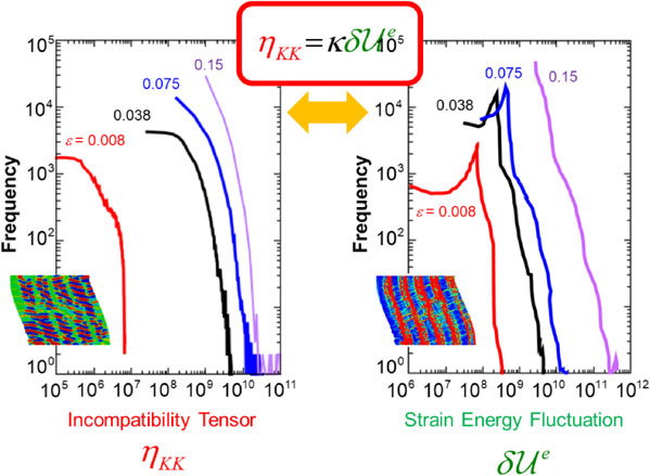
If we admit a priori the “scale-free” relationship over all the releasing energy levels, we can assume $F_{\delta \mathcal{U}^{e}}^{s} = F_{\delta \mathcal{U}^{e}}^{A}(\delta \mathcal{U}_{s}^{e}/\delta \mathcal{U}_{A}^{e})^{ - m}$ among the frequency/energy fluctuation sets, where “s” represents arbitrary scale of interest, while we regard Scale A as the smallest scale for the targeted system of concern. Further assuming the flow-evolutionary (F-E) law,36,39) i.e., $\eta_{KK} = \kappa \delta \mathcal{U}^{e}$, holds, we can rewrite this by utilizing the incompatibility tensor, as,
| \begin{equation}
{\boldsymbol{\eta}}_{Cs} = \kappa_{Cs}\left(\frac{F_{\delta\mathcal{U}^{e}}^{s}}{F_{\delta \mathcal{U}^{e}}^{C}}\right)^{\frac{1}{m}}\delta \mathcal{U}_{s}^{e}\boldsymbol{I}
\end{equation}
| (4) |
Here,
$\boldsymbol{\eta}_{Cs}$ represents interactions from Scale
s to Scale C, while κ
Cs expresses the duality coefficient that specifies energy-to-incompatibility conversion from Scale
s to Scale C. By the way, based on the interaction formalism,
32,33) we express the interaction incompatibility field with respect to Scale C regarded as the largest scale for the system targeted, as,
| \begin{equation}
\tilde{{\boldsymbol{\eta}}}_{C} = {\boldsymbol{\eta}}_{C} + \int_{C}^{A}e_{Cs}^{-1}{\boldsymbol{\eta}}_{Cs}dl_{s}
\end{equation}
| (5) |
where
eCs ≡
lC/
ls denotes the associated scale ratio with respect to Scale C. Substituting
eq. (4) into
eq. (5), we finally have,
| \begin{equation}
\tilde{{\boldsymbol{\eta}}}_{C} = {\boldsymbol{\eta}}_{C} + \langle e_{Cs}^{-1}\kappa_{Cs}\rangle \left(\frac{F_{\delta\mathcal{U}^{e}}^{A}}{F_{\delta \mathcal{U}^{e}}^{C}}\right)^{\frac{1}{m}}\delta \mathcal{U}_{A}^{e}\boldsymbol{I}
\end{equation}
| (6) |
We here put
$\langle e_{Cs}^{ - 1}\kappa_{Cs}\rangle \equiv \int_{C}^{A}e_{Cs}^{ - 1} \kappa_{Cs}dl_{s}$, otherwise taken out of the integral since they are all constants. According to Aizawa
et al.,
20) the formed kink size ranges 100/100 times with respect to the radius/height if we approximate a single kink by a cone, while the energy range extends 6 orders of magnitude, leading to,
$e_{CA}^{ - 1} = l_{A}/l_{C}:10^{ - 2}:10^{ - 4}$ and
$F_{\delta \mathcal{U}^{e}}^{A}/F_{\delta \mathcal{U}^{e}}^{C}:10^{6}$ in
eq. (3).
Assuming $\langle e_{Cs}^{ - 1}\kappa_{Cs}\rangle = 1$ for simplicity, we perform a preliminary simulation using the same model/analytical conditions as the above. Figure 11 shows the obtained simulation results in the same format as Fig. 7. We confirm a total change in the kink morphologies from Fig. 7 that without the SF nature, and greatly improved energy return map, together with a slightly but further raised flow stress level over the simulated deformation range, accompanied by “serration”. Also, different mode results in the kinking process from the original, where propagating-type of evolution from the top is observed while slight trace of the introduced MFS appears. Examining it closer, we find roughly a combination of two kinking processes, i.e., major one is the large-scale kinking starting from the top but inclined to the right that further evolves downward, while the others are the associated smaller kink banding that transversely penetrates the hard/soft boundaries toward the left. It is considered that the penetrating kink bands through the MFS boundaries contribute to one of the smallest strain energy releases, taking place along with the major kinking mode, which promotes the concentration of the energy return map in the 4th quadrant. This is also responsible for the “serrated” stress response. These aspects, together with the treatment for $\langle e_{Cs}^{ - 1}\kappa_{Cs}\rangle $, deserve further investigations.

Zooming up a representative part of the sample that yield initiations and the following growths of a group of kink bands from the sample surface, delineated by a rectangle in Fig. 11, we further scrutinize the rotation angle and the strain energy contours in Fig. 12. We confirm two things that deserve particular emphases, i.e., one is a pair of plus-minus signs in the rotation angle, demonstrating the emerging kink is surely the ridge type, while the other is the local increases in the strain energy when the growing kink bands penetrate the longitudinally-appearing hard/soft boundaries (indicated by white upward arrow in the figure). The latter tends to bring about intermittent resistance against the growths of the kink bands, making the raised flow stress level maintained high until the later stage of deformation. This is anticipated to be one of the critical mechanisms for the “primary” strengthening, serving at the same time a clue for us to model the mechanism (iv) for the “secondary” strengthening concluded in Part I.30)

For a leftover from Part I that the initial stress rises at yielding in the 45-deg. double compression simulation, we expect to make the best use of the above, i.e., such a natural description of the energy consumption in penetrating soft/hard boundaries. Since frequently bent kink boundaries have been experimentally observed in nano-meter orders28) that inevitably require introductions of c-dislocations as for them to accommodate without failure, the mechanism is considered to be responsible for the initial yield stress increase. Note, the similar phenomenon is also found to exist in MAX phase in ceramics,41) serving one of the critical mechanisms for the material to achieve ductility, and, accordingly, higher strength accompanied by plasticity. For the MAX phase, however, but it seems to allow instantaneous “void formation” on the way. For considering these aspects, we can reevaluate the importance of the “scale-free” nature in discussing the kink formation/strengthening, both in terms of the “primary” and “secondary” contexts, which do deserve further extensive investigations.
3.4 “HOP postulate” as anticipated goal of MFS project
Considering the “scale-free” nature of the strain energy release means to take contribution from lower scales down to the atomic order into account in the simulation. Kinking in the smallest scale level includes those related to the terminate boundaries,28) followed by transversely-disconnected kink boundaries that require c-dislocations for them to be compatible. If this is the case, the targeted material system can cope with the exerted severe deformation by avoiding microscopic fracture to occur, and, ultimately, lead them to exhibit enhanced toughness and/or strength. This is a kind of “underpinning effect”, without which the system would become vulnerable, even if high strength is achieved. We will tentatively call such aspect as “hierarchical strengthening” effect.
There may be, at least, one more important aspect to note, which is about further strengthening after annealing.18,19) Suzuki et al.18) and Fujii19) independently reported such phenomena in reversed bending tests, and 45-deg. double compression tests, respectively. Since they commonly mention that the kink morphologies after the test do not change so much from those before the tests at least with optical microscopy levels, near atomic-level restructurings are likely to have been taken place during the annealing process, which is thought to be a sort of microscopic “structural optimization” that further enhance the toughness/strength. If this postulate is true, we are intrinsically required to consider the above “scale-free” treatment in our simulation. This aspect will be referred to as “optimum strengthening” effect.
The above arguments are summarized in Fig. 13. For achieving the “primary kink strengthening” in an effective manner, the above two points of views play undoubtedly critical roles, which allows also the “secondary strengthening” coexist accordingly. Combining the three aspects of kink strengthening, we call it as “HOP postulate”, by taking the initial letters of these three “strengthening” mechanisms. We notice that most of the versatile experimental findings pointed out first in the introduction can all be explained in mutually-consistent manners, if we put the basis on the HOP postulate.
We ought to emphasize once again that none of the above can even be properly examined unless simulating the kinking processes with realistic morphologies, unlike any of the conventional approaches, meaning no room for such a simulation-driven comprehensive investigation becomes possible.


