1. Introduction
NiCoCrAlY coating is widely used as a protective coating for various high-temperature service parts as a thermal barrier coating with good resistance to high-temperature oxidation and corrosion.1–3) At present, the technology for preparing the coatings has become more and more mature. For example, technologies such as plasma spraying,4) electron beam physical vapor deposition,5) arc ion plating,6) and laser cladding.7) Among them, laser cladding technology is widely used due to its obvious advantages, such as high efficiency, low dilution, no pollution, and metallurgical bonding of coating and substrate.8) In particular, laser melting can replace some solid alloy parts by covering an expensive layer of alloy powder with an inexpensive metal surface, saving resources and costs.9,10)
As a general-purpose stainless-steel material, 304 stainless steel has good corrosion resistance, heat resistance, low-temperature strength, and mechanical properties, but also has the disadvantage of low hardness and poor wear resistance. To improve the hardness and wear resistance without affecting other properties, the preparation of coatings on their surface by laser melting is an effective method. Gao et al. prepared a VC-Cr7C3 composite coating on the surface of 316L stainless steel, which improved the hardness and wears resistance of the stainless-steel matrix.11) However, the laser cladding process is a rapid heating and solidification process, which leads to defects, such as inclusions and porosity on the surface of the clad layer. In addition, the coating material often has different thermal properties from the metal substrate, so it inevitably generates tensile stress residues inside the coating, making the molten layer susceptible to cracking.12)
Various surface treatment techniques have been tried to improve these defects produced during laser cladding preparation. Examples include laser remelting,13) low-temperature plasma nitriding,14,15) and plasma carbon-nitriding techniques.16) However, these techniques are both labor-intensive and costly. The high-current pulsed electron beam (HCPEB), on the other hand, has received increasing attention as a new surface treatment technology and is widely used for the surface treatment of various materials. The most distinctive feature of HCPEB is that it produces instantaneous energy densities with extremely high levels within a pulse duration of tens of nanoseconds. HCPEB irradiation of metal coatings by this technique results in a near-adiabatic localized rapid heating and melting of the specimen surface, followed by self-cooling of the substrate leading to rapid solidification. In this process, the heating and cooling rates can reach 109–1010 K/s, so the final surface microstructure will show obvious metastability, including a decrease in grain size and an increase in solid solubility to form the metastable crystal phase.17–19) Guo et al. investigated the organization and properties of Ti6Al4V alloy after different numbers of pulses. Irradiation caused the transformation of α + β binary phase to a single α-Ti phase and reduced the grain size to 100 nm.20) Samih et al. treated the surface of AISI 420 martensitic stainless steel with a high-current pulsed electron beam, which improved the microstructure, hardness, and corrosion performance in sulfuric acid solution.21) Zhang et al. used the HCPEB technique to treat the surface of 2205 stainless steel, which eliminated cracks and also improved the hardness and corrosion performance of the stainless steel.22) Cai et al. modified the NiCoCrAlYSi coating prepared by laser melting with the pulsed electron beam, which made the microstructure quite dense and the composition more uniform. The oxidation resistance of the coating was effectively improved.23) Wang et al. modified WC-Co alloy by pulsed electron beam, and the irradiation gradually healed the micro-cracks and holes on the surface of the alloy to form a compact nanostructure, which greatly improved the hardness and wear resistance of the alloy.24) It can be seen that HCPEB technology can not only solve the defects caused by laser melting but also greatly improve the performance of the materials. And there are relatively few studies on the organization and properties of HCPEB-modified stainless steel surface fusion-clad coatings.
In this paper, the HCPEB technology was used to modify the surface of NiCoCrAlY coating, and the evolutionary behavior of the coating microstructure and mechanical properties was investigated to provide some theoretical basis for improving the strength of stainless-steel surface melt coating and expanding its application.
2. Experimental Materials and Methods
2.1 Sample preparation
Firstly, the 304 stainless steel blocks (chemical composition see Table 1) are cut into 20*20*10 mm samples, each sample is polished with 200 mesh silicon carbide sandpaper, removing the oxide layer and oil on the surface. Then put it in the JP-020 ultrasonic cleaning machine for 30 minutes. A fiber-coupled semiconductor laser (LDF4000-100, Laser line Gmbn, Germany) was used to prepare NiCoCrAlY (chemical composition shown in Table 2) coating on 304 stainless steel surfaces. Laser cladding adopts synchronous powder feeding, and argon is used as a protective gas (see Table 3 for process parameters).

Table 1 Chemical composition of 304SS (mass%).
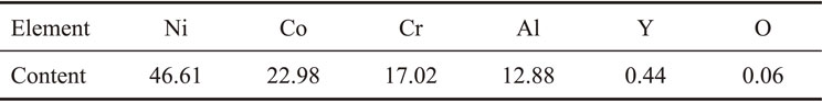
Table 2 Chemical composition of NiCoCrAlY powder (mass%).

Table 3 Parameters of the laser cladding process.
The prepared samples were polished with 400 mesh, 800 mesh, 1000 mesh, 1500 mesh, 2000 mesh and 2500 mesh SiC sandpaper in sequence. The prepared sample is ground and polished until the surface is clean and free of scratches when observed under a metallographic microscope. Then the surface of the polished samples was irradiated using the Nadezhda-2 HCPEB source. In this experiment, the irradiation acceleration voltage of the HCPEB was fixed at 27 keV, the energy density was 4 J/cm2, and the pulse width was 1.5 µs. All coating samples were treated with 15 pulses. Considering the repeatability of HCPEB irradiation and the subsequent high-temperature oxidation resistance test, all irradiated samples were treated under the same conditions to ensure the accuracy of structural analysis and performance measurement.
2.2 Characterization
The phases and oxides in the coating were analyzed by CuKα-ray diffraction (XRD). The surface and cross-sectional morphology and composition of the coating were characterized by field emission scanning electron microscopy (SEM, TESCAN MIRA3) and energy dispersive X-ray spectrometry (EDS).
2.3 Performance testing
HVS-1000 micro-Vickers hardness tester was used to test the hardness of the coating surface. The load was 10 g, 25 g, 50 g, 100 g, and 200 g, and the loading time was 5 s. The coating surface was tested every 0.2 mm for a total of 6 times and then averaged.
The HSR-2M high-speed reciprocating friction and wear tester were used to perform the wear test on the specimens. In the wear test, the applied loads were 10 N and 20 N, the friction sub-material was Si3N4, the friction distance was 5 mm, the speed was 200 r/min, and the wear time was 20 min.
The width and depth of the abrasion marks were measured by an MT-500 surface abrasion measuring instrument, and the wear volume was calculated.
3. Results and Discussion
3.1 XRD patterns of NiCoCrAlY cladding coating
Figure 1 shows the phase composition changes of the NiCoCrAlY coating before and after high-current pulsed electron beam irradiation. The results show that the phase composition did not change significantly before or after irradiation and was composed of γ/γ′ and β-NiAl phases, in which γ/γ′ phase had three characteristic peaks, left to right is (111), (200), and (220). The relative intensity of the characteristic peak (111) changed after irradiation, and the grain orientation became more obvious. Overall, an overall high angle shift of the diffraction peaks occurred after irradiation. The reasons for this phenomenon are as follows: Firstly, the effect of residual stress.25,26) Secondly, the lattice constant also has some influence. It is well known that when there are impurity atoms in the lattice, it will cause lattice distortion and thus the lattice constant will be changed. According to Table 2, the proportion of Ni element in NiCoCrAlY coating is nearly 50%, and among all the elements of the coating, only the atomic radius of Y element is larger than that of Ni element. Therefore, during the irradiation process, the Y element forms doping to other elements by solid solution, which changes the lattice constant and affects the crystal plane spacing, thus leading to the shift of diffraction peaks. However, the content of element Y is too low to show up in the XRD diffraction peaks.
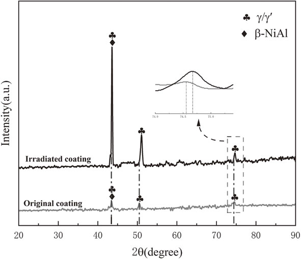
Figure 2 shows the surface morphology of NiCoCrAlY coating before and after pulsed electron beam irradiation. From Fig. 2(a)–(b), it can be seen that numerous defects such as semi-melted and unmelted particles (shown by black arrows) and holes (shown by white arrows) are distributed on the surface of the coating before irradiation. After irradiation, the coating surface became very clean, and the original defects such as holes disappeared, but many gullies and molten pits were formed (Fig. 2(c)–(d)). Since intense pulsed electron beam irradiation can cause evaporation of the coating surface, the boiling and recoil force generated during this process and the subsequent rapid solidification result in the gully shape of the irradiated coating surface. The crater-like eruption is due to the propagation of molten metal flow during rapid solidification as well as the combined effect of the difference in melting temperatures between different elements and the thermal influence between the matrix and the inclusions, and the exact location of the crater-like eruption is in the center of the inclusions. According to the available studies, it can be demonstrated27,28) that craters are more prone to nucleation at microstructural irregularities, such as grain boundaries, phase boundaries, and second-phase particles. During multiple irradiation evaporation, the first generated gullies are filled and the nucleation points, such as inclusions and second-phase particles are gradually reduced, which will lead to a smaller number of pits and improve the purification effect of pulsed electron beam irradiation.

Figure 3(a)–(c) shows a continuous magnification scan of a part of the coating surface irradiated by the pulsed electron beam. It can be seen from Fig. 3(a) that NiCoCrAlY coating has many obvious slip lines all over the surface after HCPEB irradiation, indicating that a large number of dislocations were generated on the irradiated coating surface. Secondly, it can also be seen in Fig. 3(b) that the coating surface produces many round bubbles ranging from a few microns to nanoscale. Figure 3(c)–(i) shows the SEM images of some of the bubbles in Fig. 3(b) and the corresponding EDS analysis maps. Due to the relatively low resolution of the EDS measurements, a large bubble was chosen to avoid interference from the beam-substrate interaction. The bubble has a relatively low content of Ni, Co, and Cr (Fig. 3(d)–(f)) and a high content of Al and O (Fig. 3(g)–(i)), so the main composition is Al2O3. Because the pulsed irradiation is performed in a vacuum environment, the evaporation of the elemental surface is more likely to occur in a vacuum environment compared to atmospheric pressure. At the same time, multiple irradiations lead to a repetitive deposition of energy in the surface layer, and the storage entropy of the surface increases sharply. Under such conditions, recondensation of the vapor becomes possible, and the evaporated gas falls back to the coating surface easily. Among all the elements of the NiCoCrAlY coating, the Al element has the lowest melting point, so the Al element is evaporated preferentially during evaporation. When the Al element evaporates into the air, it will inevitably react with the oxygen in the air to form Al2O3, and then gradually fall back to the surface, forming bubbles of different sizes in Fig. 3(b).
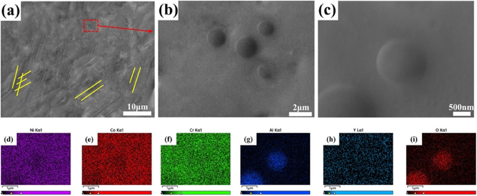
It can be seen that pulsed irradiation produces two morphologies on the coating surface, namely, the evaporative recondensation layer (tiny bubbles deposited on the surface) and the plastic deformation layer (sliding and dislocation in the surface layer). In particular, as can be seen in Fig. 3(h), the Y content in the coating is also relatively high, but only in a certain area, indicating the solid solution of element Y. This further verifies the reason for the shift of the diffraction peak of the coating after irradiation in Fig. 1.
The surface grain morphology of the coating before and after pulsed electron beam irradiation is given in Fig. 4. As can be seen from the figure, the grain size of the coating after pulsed electron beam irradiation is about 0.225 µm, while the minimum grain size of the coating before irradiation is about 5–6.25 µm. It can be seen that pulsed irradiation refines the grains on the surface of the coating, and the grains are more densely bonded.
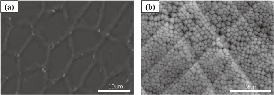
Figure 5 shows the optical morphology of the cross-section and surface of the NiCoCrAlY coating before and after the pulsed electron beam irradiation. From Fig. 5(a) and (c), it can be seen that the coating before irradiation has a very rough surface, some holes even extend to the inner part of the coating, and the denseness of the coating is relatively poor. Because the laser melting process is a rapid heating and cooling process. During the solidification of the clad layer, a sub-cooling zone appears near the solid-liquid interface, and the solute atoms are rapidly nucleated along the trajectory of the solid-liquid interface, which eventually leads to segregation and extremely non-uniform composition distribution. And from Fig. 5(b) and (d), it can be seen that the irradiated coating surface is relatively flat and uniform, the large particles with the uneven surface are reduced, and the composition within the coating is homogenized.

A 3–4 µm thick remelted layer was formed on the surface of the irradiated coating, and the segregation structures and pores within the remelted layer were also eliminated (shown in Fig. 5(b)). This is because of the overheating effect on the coating surface in a certain range (3–4 µm) during the high-current pulsed electron beam irradiation. The inclusions in the surface layer of the coating layer tend to evaporate and penetrate the melted surface, thus eliminating defects such as holes in the coating surface. The grains that did not have a chance to crystalize due to rapid cooling are also able to melt and crystalize again, resulting in finer coating grains and homogenization of the composition. In addition, there is no ultrafine grain boundary coherently precipitated (<0.4 µm) in the Ni-based superalloy coating, local melting is relatively difficult,29) resulting in a lower density and consequently, a smaller number of craters on the NiCoCrAlY fused layer surface. As a result, this smooth and dense remelted layer is formed on the coating surface, and it will significantly improve the mechanical properties of the coating.
3.3 Performance test analysis
3.3.1 Hardness test of coatings
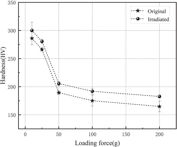
Figure 6 shows the surface hardness curves of the coatings before and after the pulsed electron beam irradiation under different loading forces. The hardness of the two coatings decreases with the increase of loading force, and the decrease of the coating after irradiation is smaller than that before irradiation. The maximum hardness of the coating before and after irradiation is 286.05 HV and 300.01 HV when the loading force is 10 g. The minimum hardness is 164.85 HV and 182.65 HV when the loading force is 200 g. The maximum and minimum hardness of the irradiated coating is higher than that of the initial coating. Figure 7 gives the surface indentation diagram for a maximum loading force of 200 g. According to the scale in the figure, the indentation area of the initial coating is about 1122.25 µm2, while that of the irradiated coating is 936.36 µm2. The indentation area of the irradiated coating is smaller than that of the pre-irradiated coating, which proves the accuracy of the measurement results.

The higher hardness of the coatings after pulsed irradiation is related to the purification and remelting caused by the irradiation. Because the surface of the coating prepared by laser cladding is covered with impurity particles and some holes and other defects (shown in Fig. 2(a) and Fig. 7(a)). After pulse irradiation, the coating surface is purified, and these holes and other defects are remedied (shown in Fig. 2(c) and Fig. 7(b)), resulting in tighter binding of the tissue. In addition, the refined grain (shown in Fig. 4(b)) increases the internal defects of the material, namely the grain boundary, thus improving the tensile strength and plasticity of the material, and the hardness value is a comprehensive reflection of the strength and plasticity value. In addition, strain hardening is considered to be the main channel limiting further dislocation movement in coatings.30) Due to a large number of dislocations on the coating surface caused by pulsed electron beam irradiation (shown in Fig. 3(a)), the movement of these dislocations is disorderly. To limit its movement, strain hardening will occur on the coating surface, and the hardness of the coating will be improved accordingly.
3.3.2 Wear resistance test and mechanism analysis of coatings
Figure 8 shows the variation curve of the friction coefficient of the coating with time before and after the pulsed electron beam irradiation. As can be seen from the graph, the coefficient of friction of both becomes smaller as the pressure increases. Frictional wear can be divided into two processes based on the trend of the friction coefficient curve, which is the break-in period and the stable wear period. The wear period of both coatings (shown in the enlarged red dashed box in Fig. 7) is relatively shorter, less than 1 minute. However, the wear period of the irradiated coating is shorter, only 0.2 min, and the wear period time is almost the same for different pressures. The initial coating has a longer break-in period than the irradiated coating, and the break-in period varies at different pressures. At a pressure of 10 N, the break-in period was 0.6 min, and when the pressure changed to 20 N, the break-in period increased to 0.8 min. It can be seen that with the increase in pressure, the wear period of the coating before irradiation becomes longer. This is because the surface of the coating prepared by laser cladding has defects such as holes, which cause the surface to be uneven and very rough, resulting in obstruction of the operation of the friction sub. When the pressure increases, the resistance of the contact surface also increases, so a longer break-in period is required to enter the stable wear phase. The short break-in time of the irradiated coating is because the pulse irradiation makes the coating surface flat and smooth, and the friction pair has little resistance to operation, which largely reduces the break-in time.

In the subsequent stable wear period, the friction coefficient curve of the irradiated coating was relatively smooth and small, with an average friction coefficient of only 1.142. In contrast, the initial coating, whose friction coefficient curve started to fluctuate more after 10 min, also had a larger friction coefficient than the irradiated coating, which was about 1.488. The main reasons for the reduction of friction coefficient after irradiation are as follows: First, the irradiation produces a uniform remelting layer with a thickness of 3–4 µm on the coating surface. The surface of the remelting layer is flat and smooth, which greatly reduces the roughness31) and increases the contact area between the friction pair and the coating surface. Therefore, the running-in time is greatly shortened and the friction coefficient is reduced. The other reason is that Al2O3 bubbles of different sizes exist on the surface of the irradiated coating (shown in Fig. 3(b)–(c)). In the process of friction, these Al2O3 bubbles will act as a lubricant, thereby reducing the friction coefficient of the coating.
The wear curve of the coating before and after the pulsed electron beam irradiation and the wear volume schematic are given in Fig. 9. From the shape of the abrasion marks in Fig. 9(a), it can be seen that the width and depth of the abrasion marks are increasing with the increase of pressure. But under the same pressure, the width and depth of the irradiated coating are considerably smaller than those of the original coating. In addition, it can be seen more visually from Fig. 9(b) that the wear of the irradiated coating is also much smaller than the initial one. For example, at a pressure of 10 N, the wear of the initial layer is around 3.29 times that of the irradiated layer. It can be seen that the high-current pulsed electron beam irradiation significantly improved the wear resistance of the coating.

Figure 10 shows the scanned morphology of the wear marks of the NiCoCrAlY coating before and after the pulsed electron beam irradiation. From the figure, it can be seen that irregular glued bumps were produced on the surface of the abrasion marks of both coatings, indicating that the coatings have undergone significant adhesive wear. Moreover, there are some furrows in some areas, indicating that the coating also underwent abrasive wear. There are more white products in the figure, indicating that the coating has also undergone oxidative wear. As the temperature rises sharply during the friction process, the elements within the coating oxidize, resulting in the formation of an oxide film (e.g., Al2O3). The oxide film forms the white residue in the figure after rubbing against the friction substrate. The surface of the coating before irradiation has more abrasive chips and deeper furrows from the friction. In addition, lamellar shedding occurred within the abrasion marks, and the amount of shedding was relatively large. The post-irradiated coating surface, on the other hand, had less abrasive debris and shallower furrows from wear, and the shedding area within the abrasion marks as well as the shedding volume was smaller. The forms of wear for both coatings are mainly adhesive wear.

Figure 11 shows the schematic diagram of the frictional wear of NiCoCrAlY coating. According to Archard’s wear calculation formula,
| \begin{equation}
Q = \frac{kNL}{3\sigma_{b}}
\end{equation}
| (1) |
Where
Q is the wear amount,
K is the adhesive wear constant,
L is the sliding distance, and σ
b is the compressive yield limit (hardness) of the material. Therefore, the following conclusions can be drawn: the wear quantity
Q is proportional to the normal load
N and the sliding distance
L, but inversely proportional to the compressive yield limit (hardness) σ
b. The experimental results show that as the applied load increases, the wear of both coatings increases (shown in
Fig. 9); The hardness of the pulsed coating is higher (shown in
Fig. 6) and the final amount of wear is smaller. It can be seen that this conclusion derived from
eq. (1) is consistent with the results of this experiment. It indicates that both coatings underwent adhesive wear, but the wear performance of the irradiated coating was significantly better than that of the unirradiated coating.

It is well known that adhesive wear is a cycle of adhesion-shearing-shortening-re-adhesion-shearing, and these Al2O3 films produced on the irradiated coating surface will first engage in adhesive wear with the friction sub. Only after the Al2O3 film fails to fall off, the friction sub will contact the coating and rub again, which undoubtedly slows down the wear consumption of the coating.32) In addition, irradiation will make the surface grain refinement, and the grain bond more closely. In this way, there will be a greater binding force between the grains, which slows friction and reduces the amount of wear. As the friction process proceeds, the oxide film breaks down and peels off, and the coating gradually falls off, resulting in a large number of abrasive chips. These abrasive chips will rub against the coating surface under the action of the friction sub, thus producing another form of friction - abrasive wear. During the abrasive wear process, these chips exert downward compressive stress on the coating surface as well as shear stress in the direction of the friction run (shown in Fig. 11). The compressive stress causes the abrasive chips to penetrate deeper and deeper into the coating, and the shear stress causes the chips to make reciprocal cutting movements on the coating surface, causing tangential deformation and fracture of the surface, resulting in more abrasive chips and causing extensive wear of the coating. The irradiated coating produces a very dense and uniform remelting layer on the surface, which, together with the surface slip and deformation caused by irradiation, results in strain hardening of the coating surface and an increase in the hardness of the surface, limiting the depth of the abrasive chips and reducing their cutting ability, effectively reducing the amount of wear of the coating.

