Abstract
The morphology of microstructure and tensile properties of Ti–48Al–2Cr–2Nb (at%) alloy rods fabricated by the electron beam powder bed fusion (EB-PBF) process were investigated with a particular focus on the influence of scan speed of the electron beam. Homogeneous near lamellar structure composed of the α2 and γ phases can be obtained in the rod fabricated under the slowest scan speed. The fine lamellar spacing which contributes to the high strength of the alloy is derived from the fast-cooling rate of EB-PBF. On the contrary, a layered microstructure comprising a duplex-like region and an equiaxed γ grain layer (γ band) perpendicular to the building direction is obtained when increasing scan speeds. We observed for the first time that an increase in the scan speed results in a narrow width of the γ band. We also found that these microstructural changes have a significant influence on the mechanical properties of the rods. The near lamellar structure exhibits higher strength compared to the layered microstructure. Whereas, the rods with the layered microstructure show large ductility at room temperature. The elongation of each rod strongly depends on the width of the γ band owing to the preferential deformation of the γ band.
1. Introduction
Powder bed fusion (PBF) that is one of the metal additive manufacturing (AM) techniques is a new fabrication technology for metallic components with complex 3D structures. In this method, electron or laser beams are used as heat sources for melting raw metal powder layer. The components are fabricated directly by melting and layering metal powder layers based on 3D-CAD data. Thus, the PBF process is expected to be applied to manufacturing processes for aerospace materials1–3) such as turbine blades and fuel nozzles used for an aircraft engine, which are usually made from difficult-to-machine materials. Another important feature of the PBF process is the dynamic temperature variation in or near the melt pool. Numerical simulation studies have revealed that the temperature gradient, solidification and cooling rates of the melt pool in the PBF process achieve 105–107 K/m, 10−1–101 m/s and 104–107 K/s,4–7) respectively. These values are much larger than those in conventional processes such as casting and forging. In addition, the solidification and cooling behaviors can be controlled through the selection of the process parameters and the scan strategy that determine the input energy density and direction of the melt pool, respectively. Therefore, the thermal field of the melt pool and its vicinity in the PBF process is referred to as a “superthermal field”. The superthermal field leads to the formation of unique microstructures in some structural materials such as Ti alloys,8–11) Ni-based superalloys12–14) and austenitic stainless steels.15,16) Interestingly, these alloys fabricated by the PBF process with unique microstructures exhibit excellent mechanical properties, compared to the alloys prepared by the conventional casting and forging. These reports suggest that PBF is a useful and an effective process for controlling not only the shape but also the microstructure and mechanical properties of metal components.
The electron beam-powder bed fusion (EB-PBF) process which is effective for fabricating alloys with high melting points can be applied to γ-TiAl alloy components. γ-TiAl alloys are the only lightweight alloys that can be used in the temperature range of 773–1073 K. These alloys are composed of three intermetallic phases: β (Ti–Al, B2), α2 (Ti3Al, D019), and γ (TiAl, L10) phases. It is well known that the morphology and volume fraction of each phase can be controlled by heat treatment. A fully α2/γ lamellar structure that satisfies the Blackburn orientation relationship is formed by heat treatment at relatively high temperatures. The microstructure changes to duplex and near γ structures with decreasing annealing temperature. The duplex structure is composed of fine equiaxed γ and α2/γ lamellar grains. As with other metallic materials, the mechanical properties of γ-TiAl alloys depend strongly on their microstructures.17,18) For instance, the α2/γ lamellar structure is important for improving the high temperature strength of the alloys, including their creep properties. On the other hand, a fine near γ structure is effective in increasing the ductility of the alloys. To reduce the weight and improve the fuel efficiency of aircraft engines by replacing Ni-based superalloy turbine blades with γ-TiAl alloys, research on microstructure control of these alloys has been conducted.19,20)
In previous studies, we developed the EB-PBF processes for fabrication of the practical Ti–48Al–2Cr–2Nb (48-2-2) alloys21–25) and β-containing γ-TiAl alloys that are expected to be next-generation alloys.26,27) We found that these alloys exhibit excellent mechanical properties owing to the formation of specific microstructures. In the case of 48-2-2 alloys, a unique layered microstructure composed of a duplex-like region and a γ band composed of equiaxed γ grains chained perpendicular to the building direction is formed under specific process conditions.21) The formation mechanism of this layered microstructure is closely related to the temperature distribution near the melt pool during the process (Fig. 1). STEP 1; Formation of a gradient microstructure. The gradient microstructure consisting of the lamellar grain, duplex and near γ regions is formed near top surface of the rod due to rapid cooling of the melt pool and a temperature distribution generated at its vicinity. STEP 2; Lowering of the fabrication stage and creation of a new powder bed by raking. STEP 3; Formation of new gradient microstructure. The gradient microstructure formed in STEP 1 is partially replaced by the new gradient microstructure associated with the thermal effect from new melt pool. It should be noted that the duplex and near γ regions formed in STEP 1 remain at the area where the thermal effect from the new melt pool does not reach. The total width of the remained duplex and near γ regions corresponds to the layer thickness at each cycle. STEP 4; Repetition of the powder raking (STEP 2) and melting (STEP 3) steps. The duplex and near γ regions remain at the bottom of the gradient microstructure for every repetition of these procedures, resulting in formation of the layered microstructure in which the duplex region and the γ band appear alternately.

In a previous study, we fabricated 48-2-2 cylindrical rods by EB-PBF process. It was also found that the tensile and fatigue properties of the alloys at room and high temperatures depend strongly on the angle θ between the building direction and the cylinder direction.21,22) For instance, the elongation of the alloys at room temperature fabricated at θ = 45° is higher than 2.5%. This is because shear deformation occurs at the soft γ bands parallel to the maximum shear stress plane. Moreover, the as built alloys with θ = 45° exhibit excellent fatigue properties compared to hot isostatic pressing (HIP) treated cast alloys, due to their high ductility and fracture toughness. It should be noted that the changes in the input energy density (ED) which can be calculated by eq. (1) cause valuations in the morphology of the layered microstructure and the mechanical properties of the alloys.25)
| \begin{equation}
\mathit{ED} = \frac{I \times U}{v \times h \times d}
\end{equation}
| (1) |
where
I is the beam current,
U is the beam voltage,
v is the scan speed,
h is the scan pitch and
d is the layer thickness. However, the influence of each process parameter such as scan speed on the morphology of the unique layered microstructure has not been investigated. Therefore, the objective of this study is to quantitatively investigate the effects of the process parameters on the morphology of the duplex-like region and the γ band of the alloys, particularly focusing on the scan speed. Furthermore, the relationships between the microstructural features and tensile properties of the alloys with the layered microstructure at θ = 45° were studied.
2. Experimental Procedure
Raw powder of 48-2-2 alloy, with a chemical composition of Al: 48.6 at%, Cr: 1.7 at%, and Nb: 2.0 at% as well as a diameter of approximately 100 µm fabricated by Ar gas atomization was used herein. Cylindrical rods of the alloy (10 mm in diameter and 90 mm in length) were fabricated using an Arcam A2X EB-PBF system at an accelerating voltage of 60 kV. The thickness of each fed powder layer was 90 µm, and θ was set to 45°, as shown in Fig. 2(a). The scan speed of the electron beam was set to 800, 1600, 2000 and 2500 mm/s. Hereafter, the rods prepared at different scan speeds are referred to as v800, v1600, v2000 and v2500. The ED was calculated using eq. (1) for each rod, and this is summarized in Table 1. It should be noted that defects originating from the lack of fusion are rarely observed in these rods, although a few Ar gas pores derived from the atomization gas trapped in the raw powder can be seen (porosity: 0.6%). Therefore, HIP treatments were not conducted for the rods before microstructure evaluations and mechanical tests.


Table 1 ED, Wγ, Dγ, Vγdp and VLdp of v800, v1600, v2000 and v2500 with standard deviation of each value.
The microstructure of each rod was observed by a scanning electron microscope (SEM) operated in its back-scattered electron mode (SEM-BSE). The longitudinal sections of the specimens for the observations were mechanically polished with waterproof emery papers of up to #2000 grit and subsequently electrically polished in perchloric acid:butanol:methanol (6:35:59 vol%) solution. The influence of the scan speed on the microstructural morphologies such as volume fraction and grain size were quantitatively investigated using an image analysis software Image J.
The yield stress (σy) and elongation (EL) of the rods fabricated by EB-PBF at various scan speeds were examined using an Instron-type testing machine. Tensile test specimens with gauge dimensions of 5.0 × 1.5 × 0.5 mm were cut from each rod parallel to the cylinder direction so that the tensile axis is parallel to the cylinder direction, as shown in Fig. 2. The specimens were mechanically polished with waterproof emery papers of up to #2000 grit and a colloidal SiO2 suspension. The tests were conducted at an initial strain rate of 1.7 × 10⁻⁴ s−1 under vacuum at room temperature. The fracture surfaces of the tensile specimens were observed by a SEM operated in its secondary electron mode. Moreover, the hardness of each constituent structure such as the γ-band and the duplex-like region was investigated using nanoindentation and Vickers hardness tests. The samples for these hardness tests were prepared using the same polishing procedure as that used for SEM observations. The maximum loads of the nanoindentation and Vickers hardness tests were set to 58.8 mN and 0.98 N, respectively.
3. Results and Discussions
3.1 Influence of scan speed on microstructure
Figure 3 shows the microstructure of 48-2-2 alloys fabricated via EB-PBF at different scan speeds. The α2 and γ phases exhibit white and gray contrasts, respectively, in the SEM-BSE images. A layered microstructure consisting of fine grain and coarse grain regions perpendicular to the building direction can be seen in v1600, v2000 and v2500 (Fig. 3(b), (c) and (d)). It is also noted that the layered microstructure is perpendicular to the building direction. The fine grain region is duplex-like region comprising the γ, lamellar and fine α2 grains. The coarse grain region is referred to as γ band because it is mainly composed of equiaxed γ grains. The total width of the duplex-like region and the γ band is approximately 90 µm for these rods, which is consistent with the powder layer thickness during the fabrication. As mentioned above, a temperature distribution is generated near the melt pool during the fabrication process.21) Consequently, a gradient microstructure consistent with the temperature of each area is formed under the melt pool. In the area exposed to a relatively low temperature (approximately 1373 K), a near γ structure is formed, resulting in the formation of the γ band. Whereas, the duplex structure is obtained in the area hold on higher temperature range (approximately 1423–1573 K). As shown in Fig. 1, repetition of these local heat treatments during fabrication are an important factor in the formation of the layered microstructure. In contrast, it is interesting to note that the layered microstructure cannot be seen in v800 (Fig. 3(a)). The rods prepared under high ED conditions had a uniform near lamellar structure. This remarkable change in the microstructure is attributed to the change in the temperature distribution from the melt pool. The temperature distribution shifts toward higher temperatures with increasing ED resulting in the formation of the near lamellar structure. This suggests that the process parameters of the EB-PBF process must be optimized to obtain the layered microstructure. It should be noted that the lamellar spacing of the near lamellar structure of v800 is approximately 200 nm (±80 nm) which is the finest value in conventional cast alloys.28) In the alloys with the same chemical composition, the lamellar spacing depends on the cooling rate during precipitation of the γ plates. This is because the degree of supercooling increases with increasing cooling rate, which is the driving force for the nucleation of the γ plates. EB-PBF is an optimal process for obtaining a fine lamellar structure because the cooling rate is several orders of magnitude faster than that of casting or conventional heat treatments.

Figure 4 shows high-magnification SEM images of the γ bands in v1600, v2000 and v2500. All of these rods have a layered microstructure, but there are notable differences in the morphology of the γ bands. The mean width of the γ band (Wγ) for each rod is listed in Table 1. Wγ of v1600 is approximately 34 µm, whereas those of v2000 and v2500 are approximately 30 µm and 24 µm, respectively. Wγ decreases with increasing the scan speed, even when the standard deviation of each value is considered. This result indicates that the γ band becomes narrower as ED decreases with increasing the scan speed. In a previous study, we reported that Wγ of 48-2-2 alloy rods fabricated by EB-PBF increases with decreasing ED.25) Pushilina et al. reported that the temperatures of the melt pool and its vicinity decrease with decreasing ED.29) Thus, the increase in Wγ is attributed to an increase in the region exposed to the relatively low temperatures, which cause formation of the γ band. In general, an increase in scan speed leads to a decrease in ED, as can be calculated from eq. (1), resulting in lower temperatures in and near the melt pool. This change in temperature distribution of the vicinity of the melt pool is expected to broaden the region of the γ band. However, we also need to consider an influence of time variation of the temperature distribution on the microstructure evolution. In the case of EB-PBF, the electron beam moves showing a snake pattern. Numerical simulation studies on the temperature distribution around the melt pool showed that the region that solidified after electron beam scanning is subsequently reheated during the melting of the neighbor powder region.30) Higher scan speed or shorter scan distances reduce the time required to reheat the solidified region.31) The temperature distribution will be shifted toward higher temperatures by shorter time to the reheating. For the range of scan speeds used in this study, the effect of the reheat time was probably more significant than the effect of the reduction in ED on the temperature distribution. Therefore, it is considered that the temperature distribution increased with increasing the scan speed, resulted in a decrease and an increase in the γ band and the duplex-like region, respectively.

In addition, Table 1 also shows the mean diameter of the equiaxed γ grains in the γ band (Dγ) for each rod. Dγ decreases slightly from approximately 14 µm (v1600) to approximately 7 µm (v2500) with increasing the scan speed. In contrast to Wγ, the standard deviation of Dγ is relatively large. The grain diameter distributions of the equiaxed γ grains in the γ bands for v1600, v2000 and v2500 are shown in Fig. 5. The large standard deviations of Dγ are attributed to the wide range of the grain diameter distributions, ranging from approximately 1 µm to more than 20 µm. However, a detailed comparison of Fig. 5(a) and (b) or (c) reveals clear differences in the grain diameter distribution of the γ grains. Although equiaxed γ grains larger than 30 µm can be obtained in the γ band of v1600 (Fig. 5(a)), they are absent in those of v2000 and v2500 (Fig. 5(b) and (c)). Moreover, the number fraction of fine equiaxed γ grains smaller than 10 µm increases with increasing scan speed. The minor difference in Dγ for each rod can be attributed to refinements in the grain diameter distribution. The finite element study investigated that the cooling rate of the area near the melt pool increases with increasing the scan speed.32) This means that the time for thermal effect from the melt pool decreases with increasing the scan speed. Thus, the growth of equiaxed γ grains is suppressed under fast scan speed conditions.

Since Wγ varies with scanning speed, the volume fraction of the duplex-like region (Vdp) also increases slightly with increasing scanning speed. As summarized in Table 1, Vdp increases from approximately 71% to 76% with increasing the scan speed. However, the difference in Vdp is less than 10%, and there is no change in the fact that the rods are primarily composed of the duplex-like region. In a previous study, the volume fraction of the equiaxed γ grains (Vγdp) and the α2/γ lamellar grains (VLdp) in the duplex-like region increase and decrease, respectively, with decreasing ED.25) However, the influence of scan speed on the morphology of the duplex-like region is insignificant. Vγdp and VLdp of the studied rods are listed in Table 1. Vγdp and VLdp are approximately 13% and 87%, respectively, regardless of the scan speed. This is thought to be due to the balance between the lower melt pool temperature due to the lower ED and the shorter time until reheating owing to the faster scan speed, resulting in a constant temperature when the duplex-like regions were formed. These results suggest that not only the maximum temperature of melt pool and its vicinity but also the time variation of the temperature distribution affects the evolution of the layered microstructure.
3.2 Tensile properties of the alloys
It was found that the morphology of the microstructure of 48-2-2 alloy rods fabricated by EB-PBF depends strongly on the scan speed. The differences in microstructural morphology are closely related to the mechanical properties of the rods. Thus, the mechanical properties of alloys can be controlled by changing the scan speed. Figure 6 shows σy and EL of v800, v1600, v2000 and v2500 deformed at room temperature. Note that the loading axis was set to an angle of 45° to the layered microstructure. The highest value of σy is observed in v800 with the near lamellar structure. σy of v800 reaches 650 MPa which is much higher than that of the cast alloys (380–500 MPa).33) Furthermore, the rod shows EL of approximately 1% which is comparable to that of HIP treated cast alloys.33) It should be noted that v1600, v2000 and v2500 which have a unique layered microstructure exhibit different tensile properties compered to v800. The most important difference in the tensile properties is ductility. These rods not only exhibit higher strength (approximately 520 MPa) than the HIP treated cast alloys but also show large ductility even at room temperature. Although σy of these alloys is independent of the scan speed, EL increases from approximately 2% to 3% with decreasing the scan speed.

To understand the fracture behavior of the rods, their fracture surfaces pulled at room temperature were observed using a SEM. As shown in Fig. 7, facets are formed on the fracture surfaces of all samples, but there are no features indicative of intergranular fracture of the γ band and the duplex-like region. Moreover, some small pores can be observed in the facets, but there is no feature indicating that they act as initiation sites for the fracture. These features observed on the fractographs suggest that the fracture of these alloys is not due to the intergranular fracture or cracking from the defects, regardless of the process parameters. Therefore, the difference in the ductility of each rod is attributed to the difference in the microstructural morphology.
3.3 Relationship between microstructural morphology and tensile properties
To investigate the key factors controlling the tensile properties of 48-2-2 alloys fabricated by EB-PBF, the nanoindentation hardness of each constituent structure was measured at room temperature. Figure 8(a) shows the nanoindentation hardness of the near lamellar structure of v800 and the duplex-like regions of v1600, v2000 and v2500 along with that of the γ band in v1600. The nanoindentation hardness of the near lamellar structure is approximately 5.5 GPa which is significantly higher than that of the duplex-like regions as well as that of the γ band. In a lamellar structure wherein the γ and α2 plates are alternately densely arranged, dislocations generated in the γ phase require a large stress to pass through the interface between the γ and α2 plates. Thus, the Hall–Petch relationship can be applied between the lamellar spacing and the strength.34) The high σy of v800 can be attributed to its fine lamellar spacing.

Let us consider the mechanical properties of alloys with the unique layered microstructure, focusing on the effect of morphology on the hardness of the duplex-like region and the γ band. The results of the nanoindentation tests show that there is no significant difference in the hardness of the duplex-like region in v1600, v2000 and v2500 (Fig. 8(a)) because Vγdp and VLdp are constant irrespective of the scan speed. Next, we focus on the hardness of the γ bands with different Dγ. It is noted that the nanoindentation test is difficult to evaluate the difference in the hardness of these γ bands because it cannot include enough grain boundaries in the small indentation. Thus, the hardness of these γ bands were measured using Vickers hardness tests. The indentation size for the Vickers hardness tests was approximately 22 µm which is at least twice as large as Dγ but smaller than Wγ. As shown in Fig. 8(b), the Vickers hardness of the γ band is also constant at approximately 325 HV for all rods. This result implies that a slight difference in Dγ between each rod is not applicable to Hall–Petch relationship and does not affect the hardness of the γ band. It can be concluded that the strength of the duplex-like region and the γ band is independent of the scan speed in the range used in this study, which is one of the reasons why σy of each rod is constant. Another important result of these hardness tests is that the duplex-like region is remarkably harder than the γ band (Fig. 8(a)). Therefore, the rods with the layered microstructure can be regarded as composite materials consisting of soft and hard layers. The theoretical strength of composite materials can be estimated by the rule of mixtures. σy of the alloys with the layered microstructure deformed in same direction is generally affected by the volume fraction of each layer with different mechanical properties. It is noted that the difference in Vdp of each rod is less than 10%. Hence, the influence of the rule of mixtures on σy of the rods used in this study is insignificant.
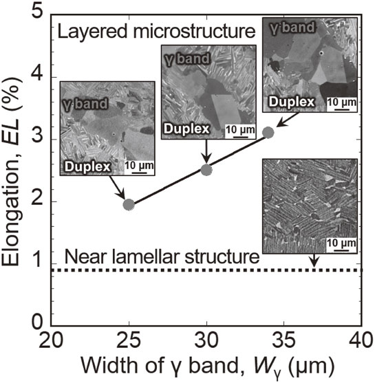
Large room temperature ductility which is one of the most important features of the alloys with layered microstructure, is originated from the presence of the γ band. The localized shear deformation is considered to preferentially occur in the softer γ band oriented at a 45° angle to the loading direction during tensile loading. Therefore, as shown in Fig. 9, the elongation of each rod strongly depended on Wγ, since an increase in Wγ leads to an expansion of the area which is responsible for deformation. It is suggested that the ductility of alloys will be improved by controlling morphology of the layered microstructure focusing on the γ band.
4. Conclusions
The microstructure and tensile properties at room temperature of 48-2-2 alloy rods fabricated by EB-PBF at θ = 45° were examined with a particular focus on the scan speed. The following conclusions were drawn from this study.
-
(1)
The layered microstructure consisting of the duplex-like region and the γ band perpendicular to the building direction can be seen in v1600, v2000 and v2500. The γ band is narrower with increasing the scan speed.
-
(2)
The near lamellar structure can be obtained by further decreasing the scan speed. The near lamellae of v800 have fine lamellar spacing because of the fast cooling rate which is one of the important features of EB-PBF.
-
(3)
v800 exhibits σy of approximately 650 MPa which is much higher than that of the cast alloys owing to the fine lamellar structure. The rods with the layered microstructure show an elongation of approximately 2–3% while maintaining strength in excess of that of cast alloys.
-
(4)
The strength of the rods with layered microstructure is constant regardless of the scan speed, since the hardness of the duplex-like region and the γ band is independent of the scan speed in the range used in this study. In addition, Vdp does not depend strongly on the scan speed, which is another reason why the strength of the rods is constant.
-
(5)
The elongation of each rod depends strongly on Wγ. This is because the localized shear deformation is considered to preferentially occur in the γ band oriented at 45° to the loading direction during tensile loading.
Acknowledgments
This study was supported by the Council for Science, Technology and Innovation (CSTI), Cross-ministerial Strategic Innovation Promotion Program (SIP) from the Japan Science and Technology Agency (JST), Japan. This work was also partly supported by JSPS KAKENHI Grant Number JP21H05196, the Light Metal research Foundation, the Light Metal Educational Foundation, Frontier Research Grants, the Japan Institute of Metals and Materials, and CREST-Nanomechanics: Elucidation of macroscale mechanical properties based on understanding nanoscale dynamics for innovative mechanical materials (grant number JPMJCR2194) from the Japan Science and Technology Agency (JST).
REFERENCES
- 1) L. Nickels: Met. Powder Rep. 70 (2015) 300–303. doi:10.1016/j.mprp.2015.06.005
- 2) W.E. Frazier: J. Mater. Eng. Perform. 23 (2014) 1917–1928. doi:10.1007/s11665-014-0958-z
- 3) W.S.W. Harun, M.S.I.N. Kamariah, N. Muhamad, S.A.C. Ghani, F. Ahmad and Z. Mohamed: Powder Technol. 327 (2018) 128–151. doi:10.1016/j.powtec.2017.12.058
- 4) D. Riedlbauer, T. Scharowsky, R.F. Singer, P. Steinmann, C. Körner and J. Mergheim: Int. J. Adv. Manuf. Technol. 88 (2017) 1309–1317. doi:10.1007/s00170-016-8819-6
- 5) W. Kan, B. Chen, H. Peng, Y. Liang and J. Lin: J. Alloy. Compd. 809 (2019) 151673. doi:10.1016/j.jallcom.2019.151673
- 6) P. Karimia, E. Sadeghi, J. Ålgårdha and J. Andersson: Mater. Charact. 148 (2019) 88–99. doi:10.1016/j.matchar.2018.11.033
- 7) M. Okugawa, Y. Ohigashi, Y. Furishiro, Y. Koizumi and T. Nakano: J. Alloy. Compd. 919 (2022) 165812. doi:10.1016/j.jallcom.2022.165812
- 8) T. Ishimoto, K. Hagihara, K. Hisamoto, S.-H. Sun and T. Nakano: Scr. Mater. 132 (2017) 34–38. doi:10.1016/j.scriptamat.2016.12.038
- 9) C.A. Biffi, J. Fiocchi, E. Ferrario, A. Fornaci, M. Riccio, M. Romeo and A. Tuissi: J. Adv. Manuf. Technol. 107 (2020) 4913–4924. doi:10.1007/s00170-020-05358-y
- 10) K. Yamanaka, A. Kuroda, M. Ito, M. Mori, H. Bian, T. Shobu, S. Sato and A. Chiba: Addit. Manuf. 37 (2021) 101678. doi:10.1016/j.addma.2020.101678
- 11) S.-H. Sun, K. Hagihara, T. Ishimoto, R. Suganuma, Y.-F. Xue and T. Nakano: Addit. Manuf. 47 (2021) 102329. doi:10.1016/j.addma.2021.102329
- 12) S.-H. Sun, K. Hagihara and T. Nakano: Mater. Des. 140 (2018) 307–316. doi:10.1016/j.matdes.2017.11.060
- 13) Y.S. Lee, M.M. Kirka, J. Ferguson and V.C. Paquit: Addit. Manuf. 32 (2020) 101031. doi:10.1016/j.addma.2019.101031
- 14) O. Gokcekaya, T. Ishimoto, S. Hibino, J. Yasutomi, T. Narushima and T. Nakano: Acta Mater. 212 (2021) 116876. doi:10.1016/j.actamat.2021.116876
- 15) T. Ishimoto, S. Wu, Y. Ito, S.-H. Sun, H. Amano and T. Nakano: ISIJ Int. 60 (2020) 1758–1764. doi:10.2355/isijinternational.ISIJINT-2019-744
- 16) J.R. Trelewicz, G.P. Halada, O.K. Donaldson and G. Manogharan: JOM 68 (2016) 850–859. doi:10.1007/s11837-016-1822-4
- 17) Y.W. Kim: JOM 46 (1994) 30–39. doi:10.1007/BF03220745
- 18) H. Clemens, W. Wallgram, S. Kremmer, V. Güther, A. Otto and A. Bartels: Adv. Eng. Mater. 10 (2008) 707–713. doi:10.1002/adem.200800164
- 19) P. Bartolotta, J. Barrett, T. Kelly and R. Smashey: JOM 49 (1997) 48–50. doi:10.1007/BF02914685
- 20) B.P. Bewlay, S. Nag, A. Suzuki and M.J. Weimer: Mater. High Temp. 33 (2016) 549–559. doi:10.1080/09603409.2016.1183068
- 21) M. Todai, T. Nakano, T. Liu, H.Y. Yasuda, K. Hagihara, K. Cho, M. Ueda and M. Takeyama: Addit. Manuf. 13 (2017) 61–70. doi:10.1016/j.addma.2016.11.001
- 22) K. Cho, R. Kobayashi, J.Y. Oh, H.Y. Yasuda, M. Todai, T. Nakano, A. Ikeda, M. Ueda and M. Takeyama: Intermetallics 95 (2018) 1–10. doi:10.1016/j.intermet.2018.01.009
- 23) K. Cho, R. Kobayashi, T. Fukuoka, J.Y. Oh, H.Y. Yasuda, M. Todai, T. Nakano, A. Ikeda, M. Ueda and M. Takeyama: Mater. Sci. Forum 941 (2018) 1597–1602. doi:10.4028/www.scientific.net/MSF.941.1597
- 24) M. Sakata, J.Y. Oh, K. Cho, H.Y. Yasuda, M. Todai, T. Nakano, A. Ikeda, M. Ueda and M. Takeyama: Mater. Sci. Forum 941 (2018) 1366–1371. doi:10.4028/www.scientific.net/MSF.941.1366
- 25) K. Cho, N. Morita, H. Matsuoka, H.Y. Yasuda, M. Todai, M. Ueda, M. Takeyama and T. Nakano: Mater. Trans. 64 (2023) 44–49. doi:10.2320/matertrans.MT-MLA2022015
- 26) K. Cho, H. Kawabata, T. Hayashi, H.Y. Yasuda, H. Nakashima, M. Takeyama and T. Nakano: Addit. Manuf. 46 (2021) 102091. doi:10.1016/j.addma.2021.102091
- 27) K. Cho, H. Odo, K. Okamoto, H.Y. Yasuda, H. Nakashima, M. Takeyama and T. Nakano: Crystals 11 (2021) 809. doi:10.3390/cryst11070809
- 28) K. Maruyama, R. Yamamoto, H. Nakakuki and N. Fujitsuna: Mater. Sci. Eng. A 239–240 (1997) 419–428. doi:10.1016/S0921-5093(97)00612-6
- 29) N.S. Pushilina, V.A. Klimenov, R.O. Cherepanov, E.B. Kashkarov, V.V. Fedorov, M.S. Syrtanov, A.M. Lider and R.S. Laptev: J. Mater. Eng. Perform. 28 (2019) 6165–6173. doi:10.1007/s11665-019-04344-0
- 30) W. Kan, B. Chen, C. Jin, H. Peng and J. Lin: Mater. Des. 160 (2018) 611–623. doi:10.1016/j.matdes.2018.09.044
- 31) H. Ali, H. Ghadbeigi and K. Mumtaz: Mater. Sci. Eng. A 712 (2018) 175–187. doi:10.1016/j.msea.2017.11.103
- 32) Y. Wang and J. Shi: Procedia Manuf. 26 (2018) 941–951. doi:10.1016/j.promfg.2018.07.121
- 33) J. Han, J. Dong, S. Zhang, C. Zhang, S. Xiao and Y. Chen: Mater. Sci. Eng. A 715 (2018) 41–48. doi:10.1016/j.msea.2017.12.092
- 34) Y. Umakoshi and T. Nakano: Acta Metall. Mater. 41 (1993) 1155–1161. doi:10.1016/0956-7151(93)90163-M

