2. Alloy Design
A new concept for the design of a quaternary Fe–Cu-based alloy system that shows LPS in Fe-based and Cu-based liquids and the formation of an Fe-based amorphous phase was suggested in the literature.26) This was accomplished using a combination map of mixing enthalpy (ΔHmix) for binary atomic pairs of the constituent elements in quaternary Fe–Cu-based alloys and a predicted quaternary phase diagram constructed by Materials Project27,28) as the database of ab initio calculations and the calculated phase diagrams focusing on the liquid miscibility gap obtained by the thermodynamic calculation using FactSage29) and FTlite database,30) resulting in the development of Fe–Cu–Nb–B-immiscible alloys with an Fe-based amorphous phase.26) The alloy design of the immiscible alloys was clarified to be effective in the development of Fe–Cu-based Fe–Cu–Nb–B,26) Fe–Cu–Si–B,31) Fe–Cu–Zr–B,31) Fe–Ag-based Fe–Ag–Nb–B,32) Co–Cu-based Co–Cu–Si–B,33) Co–Cu–Zr–B34) and Al–Pb-based Al–Pb–Co–La13) amorphous alloys with LPS and multicomponent Co–Cr–Mo–Fe–Mn–W–Ag,35) Co–Cr–Fe–Mn–Ni–Ag36) and Ti–Zr–Hf–Y–La37) high-entropy alloys (HEAs) with LPS. In the present study, we tried to adopt the above-described alloy design26) for Al–Co–La–X (X = Bi, Sn, In) alloys as the combination of Al–X (X = Bi, Sn, In) immiscible alloy system for LPS and the high glass-forming ability (GFA) of ternary Al–Co–La alloy systems.38,39)
Immiscible alloys with the simultaneous LPS and amorphous phase formation are difficult to design because of the competition between atomic pairs of the constituent elements in the alloys.26) The mixing enthalpy of i-j atomic pair (ΔHi-j) is an important indicator for predicting the LPS tendency and an amorphous phase formation tendency in alloys. Large negative values of ΔHi-j in atomic pairs are favorable for amorphous-phase formation because the liquid state is stabilized,40–43) whereas large positive values of ΔHi-j in atomic pairs leads to liquid destabilization, which results in LPS.44–46) Simultaneous occurrence in LPS and an amorphous phase formation will occur in alloys with the combination of large negative and positive values in ΔHi-j.
The ΔHi-j matrix of multicomponent alloys was effective to design the immiscible alloys with LPS and an amorphous phase.26) Figure 1 shows the ΔHi-j matrix of Al–Co–La–X (X = Pb, Bi, Sn, In) alloys for the alloy design of Al–Co–La–X immiscible amorphous alloys with LPS, where X = Pb was shown as the reference. The value of ΔHi-j in the present paper was referred from the literature.43) In Fig. 1(a), the large negative ΔHi-j values of Al–La, Al–Co, and Co–La pairs indicates the large GFA in ternary Al–Co–La alloys system, and this consisted with an amorphous phase formation in ternary Al–Co–La alloys.38,39) In Fig. 1(b), large positive ΔHi-j values in Al–X and Co–X pairs imply the liquid-phase separation of Al–Co-rich and X-rich alloys, while the large negative ΔHi-j values of Al–La, Co–La, and La–X pairs imply that La prevents liquid-phase separation from the single liquid phase to Al–Co- and X-based liquids in Al–Co–La–X (X = Pb, Bi, In, Sn) alloy systems. The significant difference in the characteristics of ΔHi-j among the constituent elements Al–Co–La–X (X = Pb, Bi, In, Sn) alloy systems was not found in Fig. 1.

The formation of the intermetallic compounds during the solidification of the thermal melt was the important factor for the alloy design of the immiscible alloys with LPS and an amorphous phase. The prediction of the existence of the intermetallic compounds in Al–Co–La–X (X = Pb, Bi, Sn, In) alloy based on the database of ab initio calculations using Materials Project27,28) was shown in Fig. 2. In Al–Co–La–X (X = Pb, Bi, Sn, In) alloy system in Figs. 2(a)–2(d), there are many intermetallic compounds in binary Al–Co, Al–La and Co–La and ternary Al–Co–La alloy systems. This corresponds to the large negative values of ΔHi-j among Al–Co, Al–La and Co–La (Fig. 1). No intermetallic compounds among binary Al–X1, Co–X1, and ternary Al–Co–X1 in Al–Co–La–X1 (X1 = Pb, Bi) alloy system were observed. Co–X2 and ternary La–Co–X2 intermetallic compounds were shown in the quaternary ground state diagrams in in Al–Co–La–X2 (X2 = Sn, In) alloy system (Figs. 2(c), 2(d)), while such compounds were not existed in Al–Co–La–X1 (X1 = Pb, Bi) alloy system (Figs. 2(a), 2(b)). No existence of the binary Al–X, Co–X and La–X, ternary Al–Co–X, Al–La–X, and Co–La–X, and quaternary Al–Co–La–X were the favorable for the alloy design in the Al–Co–La–X immiscible alloys with LPS and an amorphous phase. The ideal alloy system for the immiscible alloys with LPS and an amorphous phase, which was discussed in detail in the literature alloys,26) was not found in Al–Co–La–X alloys system (X = Pb, Bi, Sn, In) as shown in Fig. 2, and Al–Co–La–X1 (X1 = Pb, Bi) alloy system was more favorable than Al–Co–La–X2 (X2 = Sn, In) alloy system among Al–Co–La–X alloys system (X = Pb, Bi, Sn, In). Based on the above-described discussion concerning with the matrix of ΔHi-j (Fig. 1) and the predicted ground state diagram (Fig. 2), Al–Co–La–Bi alloys system was selected.

As the Al–Co–La–Bi immiscible alloys with LPS and an amorphous phase, (Al0.85Co0.10La0.05)100−xBix alloy was considered by the combination of Al85Co10La5 alloy and pure-Bi, where Al85Co10La5 was reported to form a ductile amorphous phase, and the composition was set within an amorphous forming region of Al90−xCo10Lax (x = 2–12.5) and Al95−xCoxLa5 (y = 5–17.5) alloys.38) The suitable x values in (Al0.85Co0.10La0.05)100−xBix alloy was discussed based on the empirical alloy parameters of ΔHmix43,47,48) and δ(ΔHmix)49) shown in Fig. 3, and the thermodynamic calculation shown in Fig. 4. The empirical alloy parameters ΔHmix43,47,48) and δ(ΔHmix)49) was effective to design and the predict the constituent phases in multicomponent alloys including metallic glasses, LPS-type amorphous alloys and high entropy alloys (HEAs). The alloy parameters of ΔHmix and δ(ΔHmix) was shown in the followings.
| \begin{equation}
\Delta H_{\textit{mix}} = 4\sum\nolimits_{i}\sum\nolimits_{j,j \neq i}x_{i} \cdot x_{j} \cdot \Delta H_{i - j}
\end{equation}
| (1) |
| \begin{equation}
\delta(\Delta H_{\textit{mix}}) = 4\sum\nolimits_{i}\sum\nolimits_{j,j \neq i}x_{i} \cdot x_{j} \cdot |\Delta H_{\textit{mix}} - \Delta H_{i - j}|,
\end{equation}
| (2) |
where
xi is the mole fraction of the i-th element. Δ
Hmix was corresponding to the compositional average of Δ
Hi-j, while δ(Δ
Hmix) was the parameters for evaluating the deviation of Δ
Hi-j among the constituent elements.
Figure 3 shows the Δ
Hmix − δ(Δ
Hmix) map
49) for the alloy design of (Al
0.85Co
0.10La
0.05)
100−xBi
x alloy immiscible amorphous alloys with liquid phase separation (red circles (●) and red solid line), including multicomponent alloys of 3d-transition metal high entropy alloys (3d-HEAs) (closed triangle (▲)),
47,48,50) refractory HEAs (▲),
47,48,51) HEAs for metallic biomaterials (BioHEAs) (▲),
52–54) HE brasses (▲),
55,56) light-weight HEAs (LW-HEAs) (inverse open triangle (▽)),
49,57–60) metallic glasses (close mark, ×),
40–43) and immiscible alloys with LPS and an amorphous phase (LPS-type amorphous alloys) (red sharp, #).
13,26,31–34) Metallic glasses occupied the region with large negative Δ
Hmix ∼ 0. Most of HEAs including 3d-HEAs, RHEAs, BioHEAs, HE Brasses occupied the region near Δ
Hmix ∼ 0 and δ(Δ
Hmix) ∼ 0, which was shown in blue-dashed line and index A. LW-HEAs shows the tendency to occupy the region with Δ
Hmix ∼ 0 and large positive δ(Δ
Hmix) over 10 kJ/mol, which was shown in black-dashed line and index B. Immiscible alloys with LPS and an amorphous phase shows the tendency to be occupied with large positive δ(Δ
Hmix) over 20 kJ/mol with wide range of Δ
Hmix with −40 ≦ Δ
Hmix ≦ 10 [kJ/mol], which was shown in red-dashed line and index C. In (Al
0.85Co
0.10La
0.05)
100−xBi
x alloys,
x = 20 alloy shows the tendency to be occupied the region indicated by the index C.


The liquid-phase separation in (Al0.85Co0.10La0.05)100−xBix alloys was further discussed by thermodynamic calculations using FactSage ver8.029) and FTlite thermodynamic database for alloys.30) The calculation results are shown in Fig. 4. In Ftlite database, Bi–La atomic pair was not assessed in binary atomic pairs among Al, Co, La and Bi, indicating that Fig. 4 can be used as the rough calculation data. The calculated liquid miscibility gap in the (Al0.85Co0.10La0.05)100−xBix alloy as a function of x. A clear liquid miscibility gap composed with Al–Co–La and Bi-rich liquid phases, which was existed as a thermal equilibrium state, were seen. The inset shows the magnified image of the liquid miscibility gap in an (Al0.85Co0.10La0.05)100−xBix alloy with a low Bi concentration. In the (Al0.85Co0.10La0.05)100−xBix (x = 2) alloy, the single liquid phase was obtained at 1600 K, and the separated liquid phases are stable rather than single liquid phase at 1000 K. The calculated results of the chemical composition of the separated Al-rich liquid at 800 K was the followings: Al was 85.0 at%, Co was 10.0 at%, La was 5.0 at%, and Bi 0.0 at%, respectively. The atomic composition ratio of Al/Co/La in the separated Al-rich liquid is within in the composition with high glass forming ability.38) Based on the above-described alloy design and prediction, the specimens of (Al0.85Co0.10La0.05)100−xBix (x = 2, 10, 20) alloys was tried to be fabricated.
4. Results
Rapidly melt-spun ribbons of (Al0.85Co0.10La0.05)100−x1Bix1 (x1 = 0 and 2) alloys can be successfully fabricated, while these of (Al0.85Co0.10La0.05)100−x2Bix2 (x2 = 10 and 20) alloys cannot be obtained in the present study because of the fume and high oxidation tendency. The melting temperature Tm of Bi was Tm(Bi) = 544 K, and this is much lower than that of Al (Tm(Al) = 934 K), Co (Tm(Co) = 1768 K), and La (Tm(La) = 1193 K). The significant large difference in the melting temperature between pure Bi and Al–Co–La pre-alloy ingots reads to the difficulty in the fabrication of the melt-spun ribbons in Bi-rich Al–Co–La–Bi alloys. Figure 5 shows the outer appearance of melt-spun ribbons in the non-Bi Al85Co10La5 (0Bi) and x = 2 of (Al0.85Co0.10La0.05)100−xBix (2Bi) alloys. Continuous ribbon was obtained in 0Bi alloy (Fig. 5(a)), while flake-like specimens was formed in 2Bi alloy (Fig. 5(b)). The addition of Bi element strongly affected the continuous ribbon forming ability in Al–Co–La amorphous alloys.

Figure 6 shows the XRD patterns of rapidly-solidified melt-spun ribbons in (Al0.85Co0.10La0.05)100−xBix (x = 0 and 2) alloys (0Bi and 2Bi), together with the calculated intensity of Bi62,63) and Bi3La464,65) phases. The calculated X-ray intensity was obtained by using VESTA.66) The index “W” and “F” mean the wheel-contacted and free surface side of the melt-spun ribbons, respectively. Non-Bi 0Bi alloy shows a broad peak without any sharp peaks corresponding to crystalline phases regardless the side of melt-spun ribbons, where the XRD pattern of in 0Bi alloy in Fig. 6 was obtained from both free and wheel-contacted surface sides. This indicates an amorphous phase formation in 0Bi alloy. Both a broad halo peak and sharp diffraction peaks corresponding to crystalline phases were observed in the wheel-contacted side (W) and free surface side (F) in Bi-contained 2Bi alloy. Most of sharp peaks can be indexed as the Bi3La4 intermetallic compound65,66) as indicated by black closed-circles (●). At free surface side, minor peaks corresponding to Bi phase62,63) indicated by the black open circles (○) was observed.

Figure 7 shows the DSC curves of rapidly-solidified melt-spun ribbons in (Al0.85Co0.10La0.05)100−xBix (x = 0 and 2) alloys (0Bi and 2Bi). Non-Bi (0Bi) (Black line, lower side) shows the single exothermic peak whose onset temperature was indicated by the black arrow and the index D. The crystallization temperature of 0Bi alloy was approximately 600 K, and this was similar to that reported in the literature.38) In Bi-contained 2Bi alloy (Red line, upper side), not single but double exothermic peaks cab be seen. The crystallization temperature of 2Bi alloy (E) was shifted to lower temperature side that 0Bi alloy (D). The differences in the exothermic peaks in DSC curves between 0Bi and 2Bi alloys indicates that the crystallization behavior of an amorphous phase was affected by the addition of Bi element.

Figure 8 shows the TEM microstructures of melt-spun ribbons in the Bi-contained (Al0.85Co0.10La0.05)98Bi2 (2Bi) alloy. Figure 8(a) shows a TEM-bright field (BF) image of the melt-spun ribbons. The globules were dispersed in the featureless matrix. In the selected area electron diffraction (SAD) pattern, both broad halo rings and discontinuous Debye rings were observed. The globules can be grouped into two classes based on the contrast in BF image; the black contrast globules with bend contour typical for crystalline phase as indicated by the index P, and the globules with the mixture of dark gray contrast region and black contrast region as indicated by the index Q. The globules were further investigated by STEM observation focusing on the elemental distribution as described in the latter part. The formation of an amorphous phase in Bi-contained 2Bi alloy was confirmed by the broad peak in XRD (Fig. 6), the exothermic peak in DSC (Fig. 7), the featureless contrast in TEM-BF image (Fig. 8(a)) and broad halo rings in SAD pattern (Fig. 8(b)).
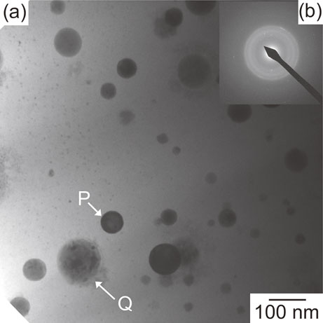
Figure 9 shows the STEM microstructures and STEM-energy dispersive X-ray spectroscopy (EDS) element mapping of the rapidly-solidified melt-spun ribbons in the Bi-contained (Al0.85Co0.10La0.05)98Bi2 (2Bi) alloy. The globules indicated by the indexes P and Q in Fig. 9 were corresponding to these in Fig. 8. STEM-HAADF image (Fig. 9(b)) shows that the globules P and Q shows the brighter contrast than the matrix. In STEM-EDS element mappings (Fig. 9(c)), Al and Co were enriched in the matrix, while La and Bi were enriched in globules P and Q. The chemical composition analysis results by in the matrix by EDS without considering the oxygen was the following: Al:Co:La:Bi = 74.9:18.7:6.3:0.2. The solubility of Bi in Al-based matrix was significantly small. The featureless contrast matrix was detected as the Al–Co–La based amorphous phase. The difference in the elemental distribution of the globules P and Q were observed in that of oxygen (Fig. 9(c5)): the enrichment of oxygen was observed in the Globules Q, while such tendency was not observed in the globule P. TEM (Fig. 8) and STEM (Fig. 9) observation indicates the formation of Al–Co–La-base amorphous ribbons with Bi–La-rich globules (P) and Bi–La–O-rich globules (Q) in the rapidly-solidified melt-spun ribbons in Bi-contained 2Bi alloy. The chemical compositions of the Bi–La-rich globule (P) evaluated by EDS was the followings, where the overlap of the globules and Al–Co–La-based amorphous matrix must be considered in the analysis results: Al:Co:La:Bi = 30.9:11.9:25.6:31.7. The Bi–La-rich globules was considered to be corresponding to Bi3La464,65) based on XRD pattern analysis (Fig. 5) and STEM observation (Fig. 9). In XRD patterns, the minor peaks corresponding to the Bi phase62,63) was observed only in the wheel contacted side of the melt-spun ribbons. The globules corresponding to Bi phase was not observed in STEM observation in the present study. The morphology of Bi phase in melt-spun ribbons was not clarified by TEM and STEM observation because of the significantly small amount of Bi phase. Figure 10 shows the magnified STEM image and STEM-EDS element mapping of the Bi–La–O-rich globules (Q) in the rapidly-solidified melt-spun ribbons in Bi-contained 2Bi alloy. Single phase structure was not observed in magnified STEM-BF (Fig. 10(a)) and STEM-HAADF (Fig. 10(b)) images of Bi–La–O-rich globule, where was corresponding to the globules Q in Figs. 8 and 9. The chemical compositions of the central region of the Bi–La–O-rich globule evaluated by EDS was the followings, where the overlap of the globules and Al–Co–La-based amorphous matrix must be considered in the analysis results: Al:Co:La:Bi:O = 47.9:12.7:14.1:4.6:20.8. The following tendency was observed in STEM-EDS element mapping images (Fig. 10(c)): (1) the globule was enriched with La (Fig. 10(c3)), Bi (Fig. 10(c4)) and O (Fig. 10(c5)), while it was the opposite for Al (Fig. 10(c1)) and Co (Fig. 10(c2)); (2) Bi was not homogenously distributed in the globule and it had the tendency to exist the inner region of the globule (Fig. 10(c4)). These characteristics indicate the formation of Bi–La–O-rich complex globules with the various regions with different chemical compositions. The sharp peaks in XRD patterns (Fig. 5) and Debye rings (Fig. 7(b)) corresponding to the oxides was not detected, and this may be due to the glassy structure formation in Bi–La–O-rich complex globules, and/or the small quantity of the oxides in the melt-spun ribbons, and/or the small structure factors of the oxides.


An amorphous phase formation in the rapidly-solidified melt-spun ribbons in the Bi-contained (Al0.85Co0.10La0.05)98Bi2 (2Bi) alloy was confirmed by the broad peak in XRD patterns (Fig. 6), the exothermic peak in DSC curves (Fig. 7), the featureless contrast in TEM-BF image (Fig. 8(a)) and STEM-BF image (Fig. 9(a)) at the matrix, and broad halo rings in SAD pattern (Fig. 8(b)). The composite of Al–Co–La-rich amorphous matrix and Bi–La-rich globules including Bi3La4 intermetallic compounds and Bi–La–O-rich complex oxides was formed in melt-spun ribbons. The combination of TEM (Fig. 8) and STEM observations including STEM-EDS (Figs. 8, 9, 10) was effective to clarify the microstructures of Bi–La-rich and Bi–La–O-rich complex oxides. The mechanism of the formation of the double shell layer structure in Bi–La–O-rich complex oxides was not clarified and this will be reported in the future works.
The composite of Al–Co–La-rich amorphous matrix and Bi–La-rich globules can be explained by the liquid phase separation without any discrepancy, as shown in the followings: (1) the liquid-phase separation to form the Al–Co–La-rich and Bi–La-rich liquids occurs as the first step. Al–Co–La-rich liquid phase formation by liquid phase separation was corresponding to the thermodynamic calculation. The formation of La–Bi rich liquid during liquid phase separation was hardly predicted by the thermodynamic calculation because of the lack of assessed data in Ftlite database, however, the significant large negative value of ΔHi-j in the La–Bi pair (Fig. 1) implies the reasonability for the formation of Bi–La-rich liquids during the liquid phase separation. (2) the major Al–Co–La-rich liquid was frozen as an amorphous matrix during the rapid cooling of the thermal melt. (3) minor Bi–La-rich separated liquids transforms to Bi3La4 intermetallic compounds and/or Bi–La–O-rich complex oxides. The present study demonstrates the alloy design of immiscible multicomponent alloys with an amorphous phase and liquid phase separation in Al-based amorphous alloys. Al–Co–La–Bi alloys was designed by the combination of the empirical alloy parameters focusing on the mixing entropy (Figs. 1 and 3), the predicted ground state diagram constructed by Materials Project for the database of ab initio calculations (Fig. 2), and thermodynamic calculations using FactSage and Ftlite database (Fig. 4). It should be noted here that the present alloy design method shown in Figs. 1–4 was effective for the alloy design not only in Fe-based26,31,32) and Co-based33,34) multi-component immiscible alloys with liquid phase separation and HEAs35–37) with LPS but also in the Al-based multi-component immiscible alloys with liquid phase separation.
