Abstract
This paper presents an overview of the recent development of incremental feeding high-pressure sliding (IF-HPS) process for grain refinement of metallic sheets with enlarged areas. The IF-HPS process is a method of severe plastic deformation (SPD) under high pressure without increasing the machine capacity. The IF-HPS process combines an incremental feeding technique with the high-pressure sliding (HPS) process so that a severely deformed area can be extended. Development of the IF-HPS process includes the use of flat-type anvils instead of groove-type anvils, which makes it easier to enlarge the SPD-processed areas. The development is also described in terms of the sliding mode and the feeding pattern, where the former is determined by the sliding distance and the numbers of the reciprocation of the sliding and the latter by the feeding distance and the feeding direction. The application of the IF-HPS process is made to metallic materials such as a Ni-based superalloy (Inconel 718), a Ti–6Al–7Nb alloy (F1295) and commercially available Al alloys (A1050, A3105, A5052 and A5182). It is shown that the grain refinement is successfully achieved so that superplastic elongation more than 400% is attained in the Ni- and Ti-based alloys, and the room-temperature tensile strength is well enhanced in the Al alloys. It is then demonstrated that the IF-HPS process is promising to extend the SPD-processed area without increasing the machine capacity. Furthermore, a new approach is suggested for material design, such as the hybrid materials composed of conventional and fine-grained materials and functionally graded materials.

1. Introduction
Recently, the technology for grain refinement is attracting much attention because it can improve the formability and strength of materials. In addition, it was reported that ultrafine-grained materials (UFG) contribute to the enhancement of material properties such as superplasticity,1) strength,2,3) hydrogen permeability,4,5) hydrogen storage performance,6) biocompatibility,7) and electrical conductivity8) as extensively documented in a recent special issue of Materials Transactions9) as well as a review for such functionalities.10)
The properties of UFG materials can be controlled by combining subsequent heat treatments.11–14) For example, for hard-to-deform materials such as superalloys for use at high temperatures, the formability should be improved only when it is required but not at high temperature in service. Then, the strength is restored in the subsequent heat treatment for practical use.15) However, how to reduce the grain size is a major issue as this overview is mainly concerned.
It is well known that the grain refinement to the submicron and/or nanometer range is achieved using the process of severe plastic deformation (SPD)16–18) where intense shear strain is introduced in the materials to reduce the grain size. The SPD process includes Equal-Channel Angler Pressing (ECAP) in which strain is introduced as the sample passes through a bend in a die,19) Accumulative Roll Bonding (ARB) in which the sample is rolled and stacked repeatedly while keeping the total thickness unchanged,20) High-Pressure Torsion (HPT) in which the sample is placed between the upper and lower anvils under high pressure and strained by rotating the upper and lower anvil relative to each other,21–23) and High-Pressure Sliding (HPS) in which strain is introduced by sliding the upper anvil with respect to the lower anvil.24) In particular, the HPT and HPS processes can be applied to hard-to-deform materials with high strength and/or less ductility25–30) because the clamping with high pressure during processing is useful to constrain the sample to prevent from breaking, and this is a good advantage over the other SPD processes.
While the HPT process utilizes a disk- or ring-shaped sample, the HPS process uses a rectangular sheet. As raised by an overview paper published earlier,31) however, the sample is limited to a small size, normally 10 mm in diameter for the HPT process and 10 × 100 mm for the HPS process. Obviously any of the size is not sufficient for practical use and thus, upsizing is an important issue to make use of the HPT and HPS processes. To respond to such an important issue, our group has developed an incremental feeding technique to combine with the HPT and HPS processes, which are called the incremental feeding HPT (IF-HPT)32) and HPS (IF-HPS),33,34) respectively. Although the use of the IF processes to SPD processes was also made by Hohenwarter35) and Ivanisenko et al.,36) their applications were combined with an HPT process and a torsion-extrusion process, respectively, to make a longer sizes of rod samples. It should be noted that a combination of the HPS process with various types of feeding processes increase the applicability of the HPS process not only to sheets37) as the IF-HPS process but also to rods38–43) and pipes44) as called multi-pass HPS (MP-HPS) process. The importance involved in the combination with the use of the feeding process is that the sample size can be enlarged without increasing the machine capacity.
In this overview, we describe the development of the IF-HPS process for enlargement of SPD-processed areas. It is shown that the development of the IF-HPS process requires the three important points: (1) the use of flat-type anvils to make sample feeding easier and sheet surface smoother, (2) the control of the sliding mode determined by the sliding distance and the numbers of the reciprocation of the sliding direction, and (3) the control of the feeding pattern determined by the feeding distance and the feeding direction. The development of the IF-HPS process is also made with the application to a Ni-based superalloy (Inconel 718), a Ti–6Al–7Nb alloy (F1295) and commercially available Al alloys (A1050, A3105, A5052 and A5182).
2. Principles of HPS and IF-HPS
2.1 HPS
Figure 1 shows (a) a schematic illustration of the HPS process and (b) a cross-sectional view. In the HPS processing, a plunger is placed in the center of the U-shaped upper and lower anvils, sheet- or rod-shaped samples are set between the anvils and the plunger, and the samples are held under high pressure via the anvils and plunger. The equivalent strain (ε) is introduced by the HPS process in proportion to the sliding distance of the plunger, X, based on eq. (1), where t is the sample thickness.
| \begin{equation}
\varepsilon = \frac{X}{\sqrt{3}t}
\end{equation}
| (1) |
The HPS process was successfully applied for grain refinement of aluminum (Al) alloys such as Al–3%Mg–0.2%Sc, A2024 and A7075, a magnesium (Mg) alloy as AZ31, a titanium (Ti) alloy as F1295 (Ti–6%Al–7%Nb), and Inconel 718 Ni-based superalloy, and it was confirmed that all the alloys exhibited superplasticity because of ultrafine-grained structures produced by the HPS process.30,45–48)
HPS processing is conducted under high-pressure for preventing sample from slippage. As the strength of the target material is higher, the required clamping force is larger.49) For example, Inconel 718 requires a clamping pressure of more than 4 GPa, so that even with the machine having 500 ton capacity developed by our group, an area of about 10 × 100 mm is the size limit that the HPS facility can successfully cover. Although further enlargement of the sample size is required for practical application, the increase in the machine capacity involves difficulty as the cost of the facility would be enormous and the anvils used would also be large, making it impractical from a cost performance. Thus, instead of increasing the machine capacity, a process was developed, which is called the IF-HPS to enlarge SPD-processed area.34)
2.2 IF-HPS
The IF-HPS process is a technique to extend the highly strained region to an entire area of large sheets by repeating the sliding for straining and the feeding for the enlargement of the strained area. Figure 2 shows (a) a schematic illustration of the IF-HPS process, (b) a cross-sectional view for detailed geometry including a sheet sample between a plunger and anvils, and (c) increasing strained area by repeating sliding and successive feeding. The feeding pattern can be extended in one or two dimensional directions as described in more detail later. This technology allows the HPS processing area to be enlarged without increasing the machine capacity.

The IF-HPS process uses flat-type anvils without grooves because the sheet should be as flat as possible without creating steps due to the grooves. The HPS process normally uses two sheets by placing one sheet between the upper anvil and plunger and the other sheet between the lower anvil and the plunger, but in the IF-HPS case, it is more suitable to use either one of them for a smooth flow of the sheet sample. Figure 2 illustrates a cross-sectional view for the use of a sheet above the plunger.
The flat-type anvil used for the IF-HPS process consists of two main parts as illustrated in Fig. 2(b): one is a flat part where intense strain is imparted by direct contact and the other is parts with slopes at both sides of the flat part. Although the flat part contacts the sheet sample when the load is little applied, strain is imparted on the sloped areas because of the high pressure sufficient to deform them. The former corresponds to a rough part because the flat part of the anvil is deliberately roughened to prevent slippage and the latter to a shiny part because the sample made contact with the smooth surfaces of the slopes at both sides of the roughened parts. The consequence of the rough and shiny areas is that strain was efficiently introduced at the rough area, but it was less at the shiny area as shown later together with the simulation of strain distribution including hardness measurement.
As shown in Fig. 3, when strain is imparted by the HPT or HPS process, hardness as well as microstructure tends to saturate after imposing a certain amount of strain.50,51) This suggests that the same microstructure can be developed if the imposed strain exceeds a critical value and thus the strain is well accumulated to make the microstructure uniform not only in the rough part but also in the shiny part after feeding the sample and successive straining in the IF-HPS process.

An important aspect in the IF-HPS process is the sliding mode, which determines the sliding distance and the number of the reciprocation of the sliding. Here, the reciprocation is carried out in the forward and backward directions both under application of load. The sample shape may change with HPS processing in a single direction, and cracks may initiate during the processing. As described later, it is recommended for the IF-HPS process to adopt the reciprocation to increase the imposed strain without crack generation.52) Here, the sliding mode is defined such that “X15-1P” represents the sliding distance of 15 mm for 1 pass in the single direction, “X7.5-2R” the sliding distance of 7.5 mm for 2 passes with reciprocation, and likewise, “X5-3R” the sliding distance of 5 mm for 3 passes including reciprocation, where the total sliding distance for all the sliding mode is 15 mm.
3. Implementation of IF-HPS
3.1 Use of flat-type anvils and effect of sliding distance
As mentioned above, the IF-HPS process utilizes flat-type anvils without grooves to make the sheet sample as flat as possible. Because the sample is less constrained without grooves, less strain may be introduced than using the grooved-type anvils in the conventional HPS processing. To examine the effect of anvils with and without grooves on the introduction of strain, single-pass processing was carried out using flat-type and groove-type anvils. Figure 4 compares the stress-strain curves after HPS processing for a single pass using (a) flat-type anvils and (b) groove-type anvils in the Inconel 718 Ni-based superalloy. The total elongations reached 220% and 710% for the sliding distances of 10 and 15 mm using the flat-type of anvils,34) while they exhibited 770 and 670% using the groove-type anvils for the corresponding sliding distances.30) The difference is significant when the sliding distance is 10 mm but no difference was observed when the sliding distance is longer as 15 mm. It should be noted that the flat-type anvils are made with a direct contact area of 10 mm in width and slopes at both sides. A single sliding process was carried out under 4 GPa at room temperature for a sliding distances of 5, 10, and 15 mm, where the position for each sliding was separated by ∼30 mm, of which separation is wide enough to avoid any influence from the sliding at the neighboring positions. The groove-type anvils are used with the same geometry as described before37) to accommodate the sample with the dimensions of 10 mm width, 100 mm length and 1 mm thickness, and the samples with such dimensions were processed for sliding distances of 5, 10, 15 and 20 mm.

The appearance of the sheet after the processing is shown in Fig. 5(a).34) Each sliding part consists of a rough surface with the width of 10 mm and shiny surfaces formed at both sides of the rough surface part. Here, the rough surface appeared because the anvil at the flat area was deliberately roughened to prevent slippage, and the shiny surfaces arose because the sample made contact with the smooth surfaces at both sides of the roughened parts. The consequence of the rough and shiny areas is that strain was efficiently introduced at the rough area, but it was less at the shiny area as shown later by simulation of strain distribution including hardness measurement. With increasing the sliding distance, the extrusion along the sliding direction is more prominent at the both edges. Figure 5(b) plots hardness variation along the white line shown in the Fig. 5(a). The hardness of each of the rough parts is constant and tends to be higher as the sliding distance increases. In the shiny part, the hardness gradually decreases to the level before the processing. It is confirmed that the strain is introduced in the shiny part so that the hardness is increased.

Figure 6(a) shows the strain distribution simulated after single sliding distances for 5, 10 and 15 mm in the Inconel 718. This simulation was conducted using SFTC’s FEM analysis software “DEFORM”. Figure 6(b) shows the strain distribution in the cross-sectional plane. In this case, the anvil is set as a rigid body and elastic deformation is not taken into calculation. The equivalent strain becomes larger as the sliding distance increases, but the direct contact area is constant under all conditions. It is also shown that strain is generated in the shiny part to extend to the unprocessed area. Provided that the strain generated in the sample is proportional to the hardness, the strain variation is very similar to the hardness variation including the extension of the strained areas toward the outside of the deformed width. The FEM simulation suggests that the strain distribution is in qualitative agreement with the hardness variation.
3.2 Effect of feeding distance
Figure 7(a) shows the appearance of the processed sample after sliding for 2 passes in Inconel 718. In the 2nd pass, the shiny part of the 1st pass is overlapped by the rough part of the 2nd pass, and new shiny part are formed on both sides. The strain distribution simulated by FEM is displayed in Fig. 7(b), where the processing conditions are the same as Fig. 7(a). The deformation of the sample is generally alike to that shown in Fig. 7(a), and the highest strain is achieved in the overlapped area. Figure 7(c) shows the hardness distribution at a cross-sectional plane after processing for 2 passes. The hardness of the overlapped area exhibits the highest values in comparison to the area with only the 1st and 2nd passed areas.

Figure 8(a) shows the stress-strain curves for the tensile specimens extracted from the individual areas after the 1st pass and the 2nd pass including the overlapped area of both the 1st and 2nd passes. The overlapped part of the 1st and 2nd passes exhibits superplastic elongation more than 400%, while the areas after the individual 1st and 2nd passes are insufficient to reach such a high superplastic elongation. The superplastic elongation was achieved because sufficient strain was accumulated to refine the grain size due to overlapping of the sliding process for straining.

Figure 8(b) plots the relationship between the sliding distance and the total elongation. The tensile specimens after the individual 1st and 2nd passes exhibit a similar trend that the total elongation increases with the sliding distance. However, for the specimen from the overlapped area, the 10 mm sliding results in the same elongation as the single pass for the 15 mm sliding, although the overlapping for the 5 mm sliding has no advantage over the others.
Inspection was also conducted on the F1295 Ti alloy to examine the effect of the overlapping on the superplastic elongation, and the stress-strain curves are depicted in Fig. 9. As the results of the Inconel 718 alloy, the overlapped area exhibits the largest total elongation reaching almost 600%, while the total elongation is less for the areas processed after the individual 1st and 2nd passes.
3.3 Enlargement of SPD area (Application to Inconel 718)
Figure 10(a) shows appearance of a 100 × 100 × 1 mm Inconel 718 sheet after processing by IF-HPS under 4 GPa using the sliding mode of X15-1P. It should be not that, for this processing, the sample feeding was made without overlapping of the sliding area because the 15 mm sliding is sufficient to produce superplastic elongation more than 400% as shown in Fig. 8(b). Shiny parts appear on both sides of the rough parts, making a striped pattern on the overall sheet. As shown in Fig. 10(b) and Fig. 10(c), the hardness is almost constant regardless of the shiny and rough parts, while thickness varies as depicted in the blue lines. The thickness tends to become thinner at the boundaries between the shiny and rough parts. It is considered that this arose because material flow occurs outward from the area under high pressure by the flat anvils. Nevertheless, this thickness variation can be amended to an equal thickness by taking advantage of the superplastic nature. In fact, we confirmed this when superplastic forming process was applied to cup forming, as described below, so that the surface becomes smooth. Alternatively, rolling may be a way to reduce the thickness variation if the sample after the IF-HPS processing is soft enough to plastically deform.

Stress-strain curves are delineated in Fig. 11 for the tensile specimens extracted from positions ① and ⑧ in Fig. 10(a) corresponding to the initial and ending parts of the IF-HPS processing. For both cases, the tensile specimens were extracted from the rough and shiny parts in each position. All specimens exhibit superplastic elongation exceeding 400%, and it is confirmed that the entire area of the specimen processed by IF-HPS has been modified to a state in which superplasticiy is expected.

Furthermore, superplastic formability was checked by extracting 30 mm diameter disks from the IF-HPS processed sheet. The disk was then subjected to a cup forming at 1073 K in air with a forming speed of 0.1 mm/s, and it was successful as shown in Fig. 12(a). However, the disk without IF-HPS processing was fractured at the flange as shown in Fig. 12(b) and many cracks appeared at the bottom of the cup even under the same forming condition. This demonstrates that the IF-HPS process is useful for the modification of the Inconel 718 to be superplastic.
3.4 Effect of sliding mode and sample edge (Application to Al alloys)
In principle, the process using HPS and IF-HPS can allow reciprocation of the sliding direction so that it is possible to control the imposed equivalent strain through the following equation
| \begin{equation}
\varepsilon = \frac{nx}{\sqrt{3}t}
\end{equation}
| (2) |
where
n is the total pass numbers and x is the distance for one way sliding pass. Thus, the total sliding distance,
X in
eq. (1) is equal to
nx (i.e.,
X =
nx), provided that no slippage occurs during the processing. Although the application of the HPS (or IF-HPS) to the Inconel 718 alloy was made through
n = 1, reciprocation of the sliding was adopted in Al alloys. As described later, this is because cracks are more likely to form in the Al alloys than the Inconel 718 Ni-based alloy. Therefore, an issue is to check if the same properties can be expected even though
n is different for the same
X. The IF-HPS process was then applied to 4 different Al alloys, A1050, A3105, A5052 and A5182.
52)
Figures 13(a) and (b) show the stress-strain curves obtained at room temperature for the A1050 and A5052 alloy, respectively, after processing by IF-HPS with 4 different sliding modes. Comparison reveals that there is clear difference between the stress-strain curves of the A1050 and A5052 alloys. For the A1050 alloy, the stress-strain behavior is almost similar to each other with the tensile strengths within the range of 160–170 MPa and the total elongation within the range 0.37–0.44. For the A5052 alloy, the stress-strain behavior is significantly affected by the sliding mode: the highest tensile strength is achieved with 700 MPa for the sample processed through X15-1P while the lowest with 320 MPa for the sample through X3-5R. The trend is opposite in the total elongation: the smallest is 0.12 and the largest is 0.27 obtained after processing through X15-1P and X3-5R, respectively.
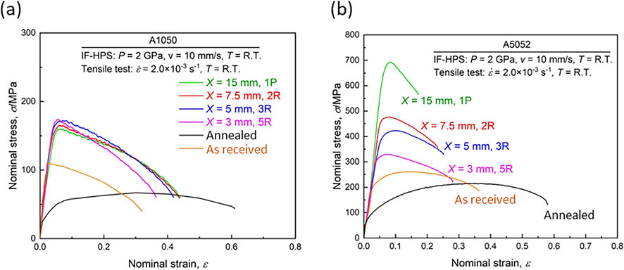
Figure 14 and Fig. 15 are TEM micrographs taken from the samples processed for the A1050 and A5052 alloys through the sliding modes of (a) X3-5R and (b) X15-1P, respectively. Bright-field images are shown on the left and dark-field images on the right taken from the diffracted beams indicated by arrows in the selected area electron diffraction (SAED) patterns in the insets. Grains with the sizes of ∼1 µm are visible for the A1050 alloy, and there appears to be no significant microstructural difference between the samples processed through X3-5R and X15-1P. Furthermore, grain boundaries are rather well-defined. The similarity of the microstructure is consistent with the stress-strain behavior in Fig. 13(a) where no significant difference in the tensile strength and the total elongation. These observations are also consistent with earlier reports on high purity Al (99.99%) that the strength as well as grain structure remains unchanged with further straining.50) By contrast, microstructural features in the A5052 alloys are different from those for the A1050 alloy: grain boundaries are ill-defined and the grain size appears to be below 1 µm in the sample processed through X3-5R, while the sample processed through X15-1P exhibits the grain size well reduced to ∼100 nm. It is considered that such microstructural features give rise to the difference in the stress-strain behavior shown in Fig. 13(b) and the former feature is attributed to an insufficient introduction of strain due to slippage.


It is important to note for practical application that the sheet should be processed without initiation of cracks. Surface observation revealed that cracks appeared in the A5052 alloy after the first pass as shown in Fig. 16(a) and such cracks propagated after further consecutive processings through X15-1P. Figure 16(b) shows appearance of some cracks after 5 consecutive processings through X7.5-2R under 2 GPa. Although the initiation of such cracks did not occur when the applied pressure is reduced to 1 GPa, the tensile strength is decreased because of the slippage as discussed in association with Fig. 13(b). For the A1050 alloy, when the sheet was processed through X15-1P, some small cracks were initiated at the edges of the sheet in the sliding direction. Thus, optimization is required between the tensile strength and the formation of cracks. It is suggested that strain should be gradually accumulated by adopting reciprocation as X3-5R or X5-3R but it is important to avoid a large gradient of strain within the short distance.

The IF-HPS process was applied to the A1050, A3105 and A5182 alloys under 1 GPa with sliding speed of 10 mm/s through X5-2R. The stress-strain curves are delineated in Figs. 17(a), (b) and (c), respectively, to examine the homogeneous development of properties such as tensile strength and ductility. Four positions where tensile specimens were extracted are labeled 1, 2, 3 and 4 in the corresponding processed sheets as shown in the insets. It should be noted that the feeding of the sheet was made from right to left so that straining by HPS was started from the left side of the sheet. Feeding and straining were repeated until the termination at position 4. The stress-strain behavior is almost the same for all alloys except for positions 1 of the A3105 and A5182 alloys where the flow stress level is invariably lower. This suggests that the IF-HPS-processed sheet is homogeneous in the tensile strength and ductility except the area after the first processing in the A3105 and A5182 alloys. This should be due to the fact that strain was not fully introduced because straining by the first sliding was made at the edge of the sheet so that constraining effect by the surrounding was insufficient. The simulation using a finite element method (FEM) by Takizawa et al.34) reported a similar trend on the IF-HPS process of an Inconel 718 alloy. However, this edge effect is not appreciable in the A1050 alloy because the sample is soft. It appears that the trend is more prominent as the materials are harder so that more strain is required to reach a hardness saturation where the hardness remains unchanged with straining. It is thus suggested that the IF-HPS process should be started away from the sample edge.

4. Potential of IF-HPS Technology
In this overview paper, we have demonstrated that upsizing of an SPD-processed sheet is feasible by feeding the sheet without increasing the machine capacity. Several feeding patterns for upsizing are suggested as illustrated in Fig. 18. The patterns utilizing the lateral feeding as shown in Figs. 18(a) through (c) are for one dimensional. The processing can be continuous if the IF-HPS is incorporated between the stages of uncoiling and coiling the sheet as shown in Fig. 19(a) or placed in a sheet flowing line as in Fig. 19(b). If the longitudinal feeding was combined with the lateral feeding as illustrated in Figs. 18(d) through (f), the IF-HPS process can be expanded two-dimensionally to a large scale sheet. An example of the sheet processed two-dimensionally is shown in Fig. 20 from the application to Inconel 718 Ni-based alloy. It should be noted that the two-dimensional expansion is an advantage over the past attempts using the combined operation of SPD processing and sample feeding.35,36) Although the extra time is required for repeated processing to cover an entire area, an important advantage over the conventional SPD processes is that there is no need of building a machine with a higher capacity which entails an immense cost and requires large-sized anvils.

Combination with the IF process can be extended to the process of HPT as demonstrated by Shigeno et al. as called IF-HPT process.32) Enlargement of the SPD-processed areas is feasible, as illustrated in Fig. 21, with a sequential movement of a sheet with respect to the two anvils where the direct contact with the sheet sample is made in a circular (or ring) form.
In addition, the IF-HPS and IF-HPT processes may be conducted to produce a sheet where straining is selectively made in a patterns as schematically shown in Figs. 22(a) and (b), respectively. For this case, the sample feeding is made by discrete selections. Thus, it is expected that the formability is improved at the processed areas through the occurrence of superplasticity when the sheet is subjected to a blow forming. As a consequence, for example, convex domes (or concave holes) may be formed in the selected HPT-processed areas as shown in Fig. 23.
5. Summary
Despite the fact that the process of severe plastic deformation (SPD) under high pressure such as high-pressure torsion (HPT) and high-pressure sliding (HPS) provides excellent improvement not only of mechanical properties but also of many functionalities, their application is limited because of the small sample size. In this overview, we introduced the importance of the sample feeding process and the combination with the HPS (or HPT) process to increase the SPD-processed areas. Thus, the combined process called the incremental feeding HPS (IF-HPS) is promising to provide potential to increase the SPD-processed area for practical application.
The development of the IF-HPS process first requires the use of flat-type anvils instead of conventional groove-type anvils so that the sheet sample can be as flat and smooth as possible. The formation of ultrafine-grained (UFG) structure is controlled by the sliding mode which is determined by the sliding distance and the numbers of reciprocation of the sliding direction. The formation of the UFG structure is also controlled by the feeding pattern which is determined by the feeding distance and directions. Feeding less distance than the width of the flat anvil gives rise to an overlap of the sliding area so that more strain is accumulated to produce UFG areas. As long as the total sliding distance is the same, crack formation may be less with more reciprocation of the sliding with shorter distance for single sliding. This importance is well confirmed in the Al alloys.
Acknowledgements
This study was conducted under a project subsidized by the New Energy and Industrial Technology Development Organization (NEDO). This study was partly supported by a Grant-in-Aid for Scientific Research (A) from the MEXT, Japan (19H00830). The HPS process was carried out in the International Research Center on Giant Straining for Advanced Materials (IRC-GSAM).
REFERENCES
- 1) J.W. Edington, K.N. Melton and C.P. Cutler: Prog. Mater. Sci. 21 (1976) 61–170. doi:10.1016/0079-6425(76)90005-0
- 2) E.O. Hall: Proc. Phys. Soc. B 64 (1951) 747–753. doi:10.1088/0370-1301/64/9/303
- 3) N.J. Petch: J. Iron Steel Inst. 174 (1953) 25–28.
- 4) H. Iwaoka, M. Arita and Z. Horita: Acta Mater. 107 (2016) 168–177. doi:10.1016/j.actamat.2016.01.069
- 5) H. Iwaoka, T. Ide, M. Arita and Z. Horita: Int. J. Hydrogen Energy 42 (2017) 24176–24182. doi:10.1016/j.ijhydene.2017.07.235
- 6) K. Edalati, M. Matsuo, H. Emami, S. Itano, A. Alhamidi, A. Staykov, D.J. Smith, S. Orimo, E. Akiba and Z. Horita: Scr. Mater. 124 (2016) 108–111. doi:10.1016/j.scriptamat.2016.07.007
- 7) P. Chen, M. Ashida, H. Doi, Y. Tsutsumi, Z. Horita and T. Hanawa: Mater. Trans. 57 (2016) 2020–2025. doi:10.2320/matertrans.MI201515
- 8) E. Ramos, T. Masuda, Z. Horita and S. Mathaudhu: Mater. Lett. 313 (2022) 131770. doi:10.1016/j.matlet.2022.131770
- 9) Z. Horita and K. Edalati: Mater. Trans. 61 (2020) 2241–2247. doi:10.2320/matertrans.MT-M2020134
- 10) K. Edalati et al.: Mater. Res. Lett. 10 (2022) 163–256. doi:10.1080/21663831.2022.2029779
- 11) T. Masuda and Z. Horita: J. JILM 67 (2017) 519–520. doi:10.2464/jilm.67.519
- 12) T. Masuda, Y. Takizawa, M. Yumoto, Y. Otagiri and Z. Horita: Mater. Trans. 58 (2017) 1647–1655. doi:10.2320/matertrans.M2017242
- 13) I.F. Mohamed, T. Masuda, S. Lee, K. Edalati, Z. Horita, S. Hirosawa, K. Matsuda, D. Terada and M.Z. Omar: Mater. Sci. Eng. A 704 (2017) 112–118. doi:10.1016/j.msea.2017.07.083
- 14) T. Masuda and Z. Horita: J. JILM 67 (2017) 179–185. doi:10.2464/jilm.67.179
- 15) Y. Takizawa and Z. Horita: Bulletin of the JSTP 5 (2022) 137–142. doi:10.32277/plastos.5.51_137
- 16) R.Z. Valiev, R.K. Islamgaliev and I.V. Alexandrov: Prog. Mater. Sci. 45 (2000) 103–189. doi:10.1016/S0079-6425(99)00007-9
- 17) R.Z. Valiev, Y. Estrin, Z. Horita, T.G. Langdon, M.J. Zechetbauer and Y.T. Zhu: JOM 58 (2006) 33–39. doi:10.1007/s11837-006-0213-7
- 18) Y. Estrin and A. Vinogradov: Acta Mater. 61 (2013) 782–817. doi:10.1016/j.actamat.2012.10.038
- 19) V.M. Segal: Mater. Sci. Eng. A 197 (1995) 157–164. doi:10.1016/0921-5093(95)09705-8
- 20) Y. Saito, H. Utsunomiya, N. Tsuji and T. Sakai: Acta Mater. 47 (1999) 579–583. doi:10.1016/S1359-6454(98)00365-6
- 21) P.W. Bridgman: Phys. Rev. 48 (1935) 825–847. doi:10.1103/PhysRev.48.825
- 22) A.P. Zhilyaev and T.G. Langdon: Prog. Mater. Sci. 53 (2008) 893–979. doi:10.1016/j.pmatsci.2008.03.002
- 23) K. Edalati and Z. Horita: Mater. Sci. Eng. A 652 (2016) 325–352. doi:10.1016/j.msea.2015.11.074
- 24) T. Fujioka and Z. Horita: Mater. Trans. 50 (2009) 930–933. doi:10.2320/matertrans.MRP2008445
- 25) T. Waitz, V. Kazykhanov and H.P. Karnthaler: Acta Mater. 52 (2004) 137–147. doi:10.1016/j.actamat.2003.08.036
- 26) K. Edalati, J. Matsuda, H. Iwaoka, S. Toh, E. Akiba and Z. Horita: Int. J. Hydrogen Energy 38 (2013) 4622–4627. doi:10.1016/j.ijhydene.2013.01.185
- 27) Y. Ikoma: Mater. Trans. 60 (2019) 1168–1176. doi:10.2320/matertrans.MF201907
- 28) H. Razavi-Khosroshahi and M. Fuji: Mater. Trans. 60 (2019) 1203–1208. doi:10.2320/matertrans.MF201916
- 29) Y. Takizawa, K. Otsuka, T. Masuda, T. Kajita, M. Yumoto, Y. Otagiri and Z. Horita: Mater. Sci. Eng. A 648 (2015) 178–182. doi:10.1016/j.msea.2015.09.023
- 30) Y. Takizawa, T. Kajita, P. Kral, T. Masuda, K. Watanabe, M. Yumoto, Y. Otagiri, V. Sklenicka and Z. Horita: Mater. Sci. Eng. A 682 (2017) 603–612. doi:10.1016/j.msea.2016.11.081
- 31) Z. Horita, Y. Tang, T. Masuda and Y. Takizawa: Mater. Trans. 61 (2020) 1177–1190. doi:10.2320/matertrans.MT-M2020074
- 32) E. Shigeno, T. Komatsu, K. Sumikawa, T. Masuda, Y. Takizawa, M. Yumoto, Y. Otagiri and Z. Horita: Mater. Trans. 59 (2018) 1009–1012. doi:10.2320/matertrans.M2018039
- 33) Y. Takizawa, K. Watanabe, T. Kajita, K. Sumikawa, T. Masuda, M. Yumoto, Y. Otagiri and Z. Horita: J. JILM 82 (2018) 25–31. doi:10.2320/jinstmet.J2017038
- 34) Y. Takizawa, K. Sumikawa, K. Watanabe, T. Masuda, M. Yumoto, Y. Kanai, Y. Otagiri and Z. Horita: Metall. Mater. Trans. A 49 (2018) 1830–1840. doi:10.1007/s11661-018-4534-2
- 35) A. Hohenwarter: Mater. Sci. Eng. A 626 (2015) 80–85. doi:10.1016/j.msea.2014.12.041
- 36) Yu. Ivanisenko, R. Kulagin, V. Fedorov, A. Mazilkin, T. Scherer, B. Baretzky and H. Hahn: Mater. Sci. Eng. A 664 (2016) 247–256. doi:10.1016/j.msea.2016.04.008
- 37) Y. Takizawa, T. Masuda, K. Fujimitsu, T. Kajita, K. Watanabe, M. Yumoto, Y. Otagiri and Z. Horita: Metall. Mater. Trans. A 47 (2016) 4669–4681. doi:10.1007/s11661-016-3623-3
- 38) T. Masuda, K. Fujimitu, Y. Takizawa and Z. Horita: J. JILM 65 (2015) 319–325. doi:10.2464/jilm.65.319
- 39) T. Masuda, K. Fujimitsu, Y. Takizawa and Z. Horita: Lett. Mater. 5 (2015) 258–263. doi:10.22226/2410-3535-2015-3-258-263
- 40) Y. Tang, K. Edalati, T. Masuda, Y. Takizawa, M. Yumoto and Z. Horita: Mater. Lett. 300 (2021) 130144. doi:10.1016/j.matlet.2021.130144
- 41) Y. Tang, K. Sumikawa, Y. Takizawa, M. Yumoto, T. Otagiri and Z. Horita: Mater. Sci. Eng. A 748 (2019) 108–118. doi:10.1016/j.msea.2019.01.071
- 42) Y. Tang, Y. Takizawa, M. Yumoto, Y. Otagiri and Z. Horita: Mater. Trans. 61 (2020) 1387–1389. doi:10.2320/matertrans.L-M2020828
- 43) T. Masuda, K. Fujimitsu, K. Sumikawa, T. Kajita, Y. Tang, S. Hirosawa, Y. Takizawa, M. Yumoto, Y. Otagiri and Z. Horita: Metall. Mater. Trans. A 52 (2021) 3860–3870. doi:10.1007/s11661-021-06347-w
- 44) Y. Tang, K. Matsuda, Y. Takizawa, M. Yumoto, Y. Otagiri and Z. Horita: Mater. Sci. Technol. 36 (2020) 877–886. doi:10.1080/02670836.2020.1746538
- 45) T. Masuda, Y. Takizawa, M. Yumoto, Y. Otagiri and Z. Horita: J. Japan Inst. Met. Mater. 80 (2016) 593–601. doi:10.2320/jinstmet.J2016012
- 46) K. Watanabe, M. Ashida, T. Masuda, P. Kral, Y. Takizawa, M. Yumoto, Y. Otagiri, V. Sklenicka, T. Hanawa and Z. Horita: Mater. Trans. 60 (2019) 1785–1791. doi:10.2320/matertrans.ME201924
- 47) T. Masuda, T. Fujimitsu, Y. Takizawa and Z. Horita: J. Japan Inst. Met. Mater. 80 (2016) 128–133. doi:10.2320/jinstmet.J2015046
- 48) M. Ashida, P. Chen, H. Doi, Y. Tsusumi, Z. Horita and T. Hanawa: Proceedings of the International Workshop on Giant Straining Process for Advanced Materials (GSAM2017), (2017), ISBN978-4-944005-24-6, pp. 43–44.
- 49) K. Edalati, Z. Horita and T.G. Langdon: Scr. Mater. 60 (2009) 9–12. doi:10.1016/j.scriptamat.2008.08.042
- 50) Y. Ito and Z. Horita: Mater. Sci. Eng. A 503 (2009) 32–36. doi:10.1016/j.msea.2008.03.055
- 51) K. Edalati and Z. Horita: Mater. Trans. 51 (2010) 1051–1054. doi:10.2320/matertrans.M2009431
- 52) T. Komatsu, T. Masuda, Y. Tang, I.F. Mohamed, M. Yumoto, Y. Takizawa and Z. Horita: Mater. Trans. 64 (2023) 436–442. doi:10.2320/matertrans.MT-LA2022032


