Abstract
Processing by tube high-pressure shearing (t-HPS) is a relatively new technique now in the early phase of development within the family of severe plastic deformation (SPD) by comparison with other established techniques such as Equal-Channel Angular Pressing, High Pressure Torsion and Accumulative Roll Bonding. Nevertheless, the technique has demonstrated already its capability to restructure materials to featured microstructures that not reached by the other processing procedures and, in addition, it is efficient in refining the microstructure in a way that is consistent with the other SPD processes.
The initialization and development of the principle and processing technique of t-HPS is reviewed in this report together with the microstructure and property improvements of the processed materials. It is demonstrated that there is a unique capability of t-HPS in preparing distinctly featured microstructures and producing unprecedented properties of the processed material by comparison with other SPD processes. As a new SPD technique that is currently under development, several open topics are proposed which are significant for obtaining an understanding of the physical characteristics of t-HPS and for further exploiting the potential of t-HPS in establishing unprecedented properties through distinct and unusual microstructures.
1. Introduction
It is well established that High-Pressure Torsion (HPT) provides an opportunity to achieve very high strength and exceptional grain refinement and thereby to provide promising opportunities for further fundamental investigations and applications.1–7) Nevertheless, the HPT process introduces a radial strain gradient that makes it difficult to correlate material characteristics along the chords of disk samples. Furthermore, the disks are usually exceptionally thin and inhomogeneous in the through-thickness directions of disks of some materials, such as magnesium and zirconium alloys, after processing by HPT.8,9) To remove these strain heterogeneities and to produce relatively large samples,10–12) and also to provide a monotonic deformation process characterized by constant shear direction and strain planarity throughout the deformation process or by simple shear13,14) to a high strain level, a new friction-driven shear process other than HPT was developed.
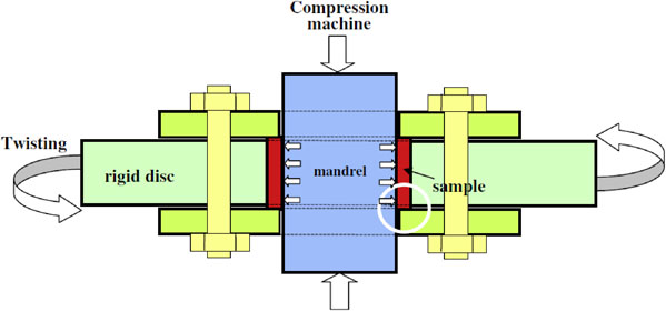
The principle of this new process is depicted schematically in Fig. 1(a).12,15) Thus, the characteristics are 1) a sample in the form of a tube is radially confined between a central mandrel and an outer cylinder; 2) a sufficiently high hydrostatic pressure is introduced in the tube wall so that the frictional forces at the interfaces between the sample-mandrel and the sample-cylinder are sufficiently high to prevent any localized slip between the interfaces; and 3) by fixing the mandrel and rotating the outer cylinder (or vice versa), a simple shear strain is then produced in the tube wall.10–12)

During this process the shear plane is always parallel to the cylindrical surface which is vertical to the tube radius. By contrast, during general tube torsion or twisting, the shear plane is always the cross-section and lies parallel to the tube radius, as depicted schematically in Fig. 1(b).15) This guarantees that the strain gradient along the direction perpendicular to both the shear plane normal (SPN) and the shear direction (SD) is zero in t-HPS, and this assures planarity for simple shear; whereas in HPT the strain along the direction perpendicular to SPN and SD is proportional to the radius r, which leads to a non-zero strain gradient and thereby violates the planarity of simple shear.
The development of this alternative shear technique may be classified into three sectors with different names as Rotation Shear (RS),10) High Pressure Tube Twisting (HPTT)11,16) and tube High-Pressure Shearing (t-HPS),12) where they include the same core concept of friction-driven azimuthal shear at the tube wall as developed independently by three different scientific groups. In practice, tube High-Pressure Shearing (t-HPS) will be used in general in this review for the following reasons: 1) It is clear from the general principle of the process that a high pressure is critical but this is not included in the name Rotation Shear; 2) Fig. 1 clearly depicts the difference of this process from conventional HPT. It is suggested that the term twisting should be avoided in addition to torsion in naming this process since otherwise it is easy to confuse with torsion. For example, in a popular dictionary such as Merriam-Webster, the word “torsion” is defined as “the twisting or wrenching of a body by the exertion of forces tending to turn one end or part about a longitudinal axis while the other is held fast or turned in the opposite direction”. Nevertheless, to respect the names introduced by individual contributors, and also for consistency with history, either RS or HPTT will also be used in this review when reviewing the relevant literature.
Details of 1) the development of this new deformation method from rotational shear, through HPTT, to t-HPS; 2) the microstructure and property evolution concurring other severe plastic deformation (SPD) processes; 3) the featured microstructures and unprecedented properties by t-HPS will be presented in the following sections. A concluding summary, the overall perspective and open topics on t-HPS will be presented at the end of this report.
2. The Historical Development of the Deformation Method
Shan et al.10) first raised the concept of rotation shear, where it was assumed that a uniform shear deformation could be introduced into materials during the process under a pressure lower than HPT. It was suggested for this RS method that there are the following characteristics:
-
1)
Using a ring-shaped cylinder sample.
-
2)
The inner surface is fixed and the outer surface is rotated by the friction, so that the shear deformation takes place through the radius from the outer to the inner surface. This is illustrated in Fig. 2.
The experimental rotation shear of a commercial purity (CP) Al was successfully conducted using a pressure of 800 MPa at room temperature to a rotation shear of π or an average shear strain of 8.37.
For initial HPTT testing, axial compression of the mandrel was utilized to force it to expand elastically in the radial direction and this expansion is constrained by the tube sample and the outer cylinder so that a hydrostatic stress is expected to build up in the tube11) as shown in Fig. 3. However, the level of hydrostatic pressure is limited for such testing, so that an axial force is applied directly on the tube ends in a later design using a stepped mandrel together with a stepped cylinder.16) Thus, HPTT was developed as an effective method of severe plastic deformation (SPD) and it was used to investigate the microstructure, texture and strength evolution upon the increase of the HPTT strain in CP Al, AA5086, IF steel, pure Mg, pure Cu, etc. to a high strain level of ∼65.
For tube high-pressure shearing, direct compressions from the die parts are applied on the tube sample to build up a hydrostatic pressure that is sufficiently high to ensure a state of static friction between the tube wall and the mandrel or cylinder, so that a relative rotation can be established between the inner and outer wall surfaces of the sample tube. A shear deformation is thus produced in the tube wall. The schemes to conduct such direct compression were searched systematically for t-HPS and, after experimental verification, the four most effective schemes are listed here:
-
1)
Compress directly on the two ends of the tube, using upper and bottom pressure rings in the gap between the mandrel and the cylinder, as shown in Fig. 4(a).12,17) In this scheme all the die parts and also the sample tube are straight.
-
2)
Combining the upper pressure ring with the straight mandrel in the previous scheme to form a unitary stepped mandrel, and combing the bottom pressure ring with the straight cylinder to form a unitary stepped cylinder, or vice versa, a new scheme can be established as a close variant to the previous scheme to compress directly on the two ends of the tube, as shown in Fig. 4(b). The combination of this scheme and the wedge effect directly leads to the patented method.18) This scheme is also presented in the work by Toth’s group16) for HPTT.
-
3)
Compress directly on the tube wall by introducing a small tapper angle to the tube. This scheme also has the advantage of magnifying the axial pressure to multiples by the well-known wedge effect. Obviously in this scheme the mandrel has the same tapper angle with that of the tube sample, and the cylinder inner surface is concave with a same tapper angle to hold the tube sample, as shown in Fig. 4(c) which was also patented.18,19)
-
4)
A combination of schemes 2) and 3) leads to a scheme of compression directly on both the tube ends and the tube wall, as shown in Fig. 4(d).18,19)

The schemes where the compression is applied directly on the ends of the tube sample can be represented by E, the first letter of End. Thus the scheme in Fig. 4(a) and (b) are designated E1 and E2. The schemes where the compression is applied directly on the wall of the tube sample can be represented by W, the first letter of Wall and Wedge. Thus, the schemes in Fig. 4(c) and (d) are designated W and EW. Using these effective direct compression schemes to establish a high hydrostatic pressure in the tube wall of the sample, t-HPS was conducted to a record high strain level of 1600∼2000 in monotonic shear deformation.20) This was exploited to produce featured microstructures other than those obtained by other SPD methods and thereby to achieve unprecedented properties.
3. Strain and Stress Formulations
3.1 Average strain and strain gradient
Under the assumption of uniform deformation in the tube wall, Shan et al.10) derived the first equation to calculate the average shear strain γ in the tube wall in rotation shear:
| \begin{equation}
\gamma = \frac{\alpha R}{R - R_{i}}
\end{equation}
| (1) |
where α is the rotation angle and
R and
Ri are the outer and inner radius of the ring sample, respectively. Toth
et al. derived the same equation for the HPTT process.
11)
Alternatively, the shear strain introduced in the tube wall can be formulated more precisely using the approach depicted in Figs. 1(a) and 5.12,15) Thus, a straight radius segment within the tube wall is sheared to a slanting curve when the outer surface of the tube rotates through an angle α during t-HPS. Corresponding to an increment of α, Δα, radius r is increased to r + Δr. The local tangential shear strain is thus:
| \begin{equation}
\gamma = \text{tg}\varphi = \frac{r\Delta\alpha}{\Delta r} = \frac{r}{dr}d\alpha
\end{equation}
| (2) |
| \begin{equation}
\theta = \int \text{d}\alpha = \int\nolimits_{R_{i}}^{R}\gamma\frac{\text{d}r}{r}
\end{equation}
| (3) |
For the case where γ is assumed to be homogeneous or constant in the wall:
| \begin{align}
& \alpha = \gamma\int\nolimits_{R_{i}}^{R}\gamma\frac{\text{d}r}{r} = \gamma \ln\frac{R}{R_{i}}\\
& \gamma = \frac{\alpha}{\ln(R/R_{i})}
\end{align}
| (4) |
The first order approximation of this equation at Ri → R leads to $\gamma = \frac{\alpha R}{R - R_{i}}$, which is the same as eq. (1) given by Shan et al.10) and Toth et al.,11) respectively.
To obtain the strain distribution in the tube wall under t-HPS, a material model and stress field must be introduced in addition to the geometrical approach as given above. Considering a cylindrically symmetric volume element in the tube wall, ignoring the edge effect at the ends of the tube sample and ignoring the axial friction, and then applying a balance of moment about the tube axis of the volume element leads to a tangential shear stress:
| \begin{equation}
\tau = C/r^{2}
\end{equation}
| (5) |
where
C is an integral constant.
For the case of a simple constitutional equation of the form τ = Aγn, the shear strain can be expressed as a function of shear stress so that
| \begin{equation}
\gamma = \left(\frac{\tau}{A}\right)^{1/n}{} = \left(\frac{C}{A}\right)^{1/n}\frac{1}{r^{2/n}}
\end{equation}
| (6) |
Substituting to eq. (3) after integration and transformation leads to
| \begin{equation}
\gamma = \frac{2}{n}\frac{\alpha}{1 - (R_{i}/R)^{2/n}}\left(\frac{R_{i}}{r}\right)^{2/n}
\end{equation}
| (7) |
For a more general case, the constitutional equation has the form of τ = τ0 + Aγn, or an even more complicated form, and the shear strain distribution in the tube wall can also be obtained following the same procedure in either analytical form when the relevant functions are integral or at least in digital form with digital integrations.
Equation (4) was initially shown at the Bulk Nanostructured Materials Conference (BNM-2009) in Ufa in 2009 together with the t-HPS design and the equation was formally presented together with the derivation of eq. (7) at BNM-2011.12) These same equations were also developed in parallel work and published by Toth et al.21,22) The existence of a strain gradient in the t-HPS tube wall was confirmed by FEM simulations19) and also by experimental measurements in Cu, Al and IF steel.11,12,16,19,21,22)
It is worth noting that the strain levels demonstrated in these papers were estimated according to eq. (1), (2) or (7) of ideal t-HPS (or RS and HPTT) using approximate material models when necessary. Since no measure is available at present to detect the slip between the surfaces of the sample tube walls and the die, and no measure to directly validate the suitability of the materials models selected, it means that so far these strain levels are only approximate estimates. This means these data are in a similar situation to the other friction-driven SPD process of HPT.
3.2 Average shear stress and stress-strain relation
The average shear stress τ can be obtained by use of the equality of external and internal plastic work.22) During a rotation of Δθ, the increment of the external plastic work ΔW is:
| \begin{equation}
\Delta W = T\Delta\theta
\end{equation}
| (8) |
where
T is the rotation torque. At the same time, the increment of plastic work in the volume
V of the tube is an integral over the whole volume of the tube, so it can be written in the form:
| \begin{equation}
\Delta W = \int\nolimits_{V}\ \tau \Delta \gamma dV = \tau \Delta \gamma\int\nolimits_{V}\ dV = \tau \Delta \gamma(R^{2} - R_{i}{}^{2})\pi h
\end{equation}
| (9) |
where
h is the height of the tube. Substituting
eq. (4) and
(8) into
eq. (9) leads to the following relationship for the average shear stress:
| \begin{equation}
\tau = \frac{T\,\mathit{ln}(R/R_{i})}{(R^{2} - R_{i}{}^{2})\pi h}
\end{equation}
| (10) |
The average strain (eq. (4)) and stress (eq. (10)) permit the construction of a stress-strain relation. The torque (T) versus rotation angle (θ) data for different materials were collected by Toth’s group16,21) so that the average strain-average stress curves are obtained as shown in Fig. 6 for different materials.

According to eq. (10), for industrial application of t-HPS, there exists a limit on the aspect ratio h/R of the tube processed by t-HPS, and this limit is based on the ratio of allowable shear stress of the t-HPS mandrel and the deformation resistance to the processing tube.16,23) Alternatively, according to the above described principle of t-HPS, geometrical and mechanical similarity24) could be easily maintained in scaling up for industrial applications, and the complex barriers retarding the scale up of HPT, such as the increased strain heterogeneity,25,26) seems not as obvious because of the different principle between t-HPS and HPT. This will need to be examined by further experimental investigations.
4. Microstructure and Property Evolution Compared with Other SPD Processes
CP Al was first successfully deformed, using a pressure of 800 MPa at room temperature to a rotation angle of π in RS or an average shear strain of 8.37. The sample was refined to a grain size of 0.6∼0.7 µm as shown in Fig. 8 with a Vickers micro-hardness of 45∼58 Hv. This is comparable to typical representative severe plastic processing by Equal-Channel Angular Pressing (ECAP) and only slightly coarser than the saturated refinement limit of HPT, as is evident from the data in Table 1. It is reported that 8 passes of ECAP via route C using an 90° die at room temperature gives a grain size of 0.68 µm for CP Al, as shown in Fig. 7(b).27) By comparison, HPT to a strain of 600 with a pressure of 5 GPa at room temperature gives a grain size of 0.5 µm and a micro-hardness of ∼64 in a similar CP Al.28)

Table 1 Comparison of grain refinement in CP Al by various SPD processes.
The microstructure, texture and strength evolution upon an increase of HPTT strain up to ∼65 were extensively investigated using CP Al, AA5086, IF steel, pure Mg and pure Cu and the results were consistent with the generally observed basic phenomena observed in SPD processes.21) These evolutions will be described in the following subsections. The evolution of grain size and grain aspect ratio during t-HPS is also presented in line with the HPTT data.
4.1 Grain refinement
The evolution of grain size and grain aspect ratio with increasing t-HPS strain is consistent with other typical SPD processes.29) Figures 8 and 9 give an example of data for a 5 nine (5N) high purity Al where the grains were refined by the t-HPS rotations.14) Some characteristics of this grain refinement are as follows:
-
1)
There is a clear radial gradient of grain size with smaller vs. coarser grains at closer to the inner vs. outer surfaces as is clearly demonstrated, especially in the center right column in Fig. 8, indicating the effect of radial gradient shear strain, characteristic of t-HPS, as indicated by eq. (6). It is noted that this grain size gradient falters to almost an un-recognizable level in the sample rotated to 2π, as indicated by the right column in Fig. 8.
-
2)
The grain size data demonstrates a clear general trend of saturation at 8 ± 5 µm where this corresponds to an equivalent strain of ∼30,14) as shown in Fig. 9. The faltering radial grain size gradient arises because the strain level at the outer surface of the tube sample rotated to 2π reaches the grain size saturation strain of ∼30. This grain size saturation trend fits well with published results where numerous experiments have shown that the evolution of the microstructure and the properties during SPD processing tend towards homogeneity by straining.30–35) Many metals processed by HPT begin to demonstrate saturation features at equivalent strains between 10 and 30.29,36–38)
-
3)
The grain aspect ratio increases first, then decreases and saturates also, accompanying the grain refinement to a value of ∼1.6. This fits the results of dynamic recrystallization at large strains in SPD processes which lead to nearly equiaxed refined grains.30)

Although some data from previous work could not demonstrate the saturation because of the limited strain level that was reached by the processing in this early work,10) all results follow the same general trend of grain refinement together with t-HPS.
This similar trend was also demonstrated by Toth et al. using different materials of CP Al, AA5056 and IF steel.16,21) CP Al saturates at a grain size of ∼0.65 µm up to a shear strain level of 44.16) The results fit well with most reported grain sizes after ECAP and HPT of the same CP Al39–42) as shown in Table 1 although a dual grain size was also reported in some work.43)
IF steel was reported to have a grain size of ∼0.25 µm after an HPTT shear strain of 14.621) where this grain size is nearly half that of ECAP IF steel,44) and comparable to HPT.45) Pure copper was reported as refined to a grain size of ∼0.25 µm after an HPTT equivalent strain of 65.21) Although the exact purity was not specified, considering the less significant effect of purity on grain size refinement by deformation46) and the high strain level imposed, this suggests a saturated grain size quite close to that obtained in HPT of 4N copper.47) HPTT of pure Mg to a strain of 2.8 and 3.9 gave grain sizes of 1.3 and 1.1 µm while HPT of Mg produced a grain size of 0.32∼0.6 µm.48,49) It appears that HPTT of pure Mg to a strain of 3.9 is not sufficient to reach saturation.
4.2 The evolution of grain boundary disorientation and fraction of HAGBs
The next-neighbor disorientation distribution evolution observed in FCC and BCC metals upon HPTT strain follows the general trends of a single peak distribution at lower strains with one peak at disorientations smaller than ∼20°, double peaks in the middle range of strains with a new peak appearing at disorientations larger than ∼40°, and finally at high levels of strains there is a transformation to one peak at disorientations larger than ∼40° where this approaches the well-established Mackenzie curve.50) This general trend is fully demonstrated by research on CP Al HPTT-processed up to a shear strain of 24.51) This evolution trend of the next-neighbor disorientation distribution is the same as that observed in HPT of commercial pure Al.52,53) It is obvious that this kind of disorientation distribution evolution yields a monotonic increase of high-angle grain boundaries (HAGBs) as shown in Fig. 10, approaching saturation at ∼90% at a high strain level.51) This evolution and even the saturation value of the HAGB fraction are the same as that observed in HPT of commercial purity Al.54) The limited disorientation distribution data of pure Cu at HPTT equivalent strain of 16 and 65 indicates that the same evolution trend is followed21) as that demonstrated in CP Al.

BCC structured IF steel is reported to demonstrate similar trends of disorientation distribution upon HPTT strain. Figure 11 gives this distribution at several HPTT strains21) together with the grain boundary misorientation data for HPT of commercial pure Al in Fig. 12 for comparison.52) Although the next-neighbor disorientation distribution evolution is complicated because of the interaction of both twinning and slipping deformation during HPTT processing, the trend is clear from the limited data available that the distribution also approaches the random Mackenzie curve at higher HPTT strain level, as shown in Fig. 11.21)
4.3 The evolution of texture
Texture evolution in CP Al was investigated up to an HPTT shear strain of 44 and all measured textures confirmed the existence of simple shear textures. For all cases, the main deformation texture component was the C, which is defined by {100}//SPN and ⟨011⟩//SD where this is basically a rotated cube orientation. Other well visible texture components are $\text{A1}^{ \star }/\text{A2}^{ \star }\{ 11\bar{1}\} \langle 2\bar{1}1\rangle $ and $\text{A}/\bar{\text{A}}\{ 11\bar{1}\} \langle 1\bar{1}0\rangle $.16) The texture index decreases from ∼4.2 for the initial CP Al tube sample, passing through a minimum and reaching a peak at the middle stage of the shear strain, and thereafter decreasing to a low value of about 1.3 as shown in Fig. 13.16) These texture components and texture index evolutions upon shear strain in HPTT are generally the same as those observed in HPT of commercial purity Al as reported elsewhere52,53) where the dominant deformation mode is also shear. Figure 14 plots the effect of accumulated deformation on the evolution of the texture index in the HPT processing of CP Al.53) It is easy to identify the similarity between Fig. 14 for HPT and Fig. 13 for HPTT.

For HCP structured pure Mg, the main texture characteristic upon HPTT is the appearance of the B fiber texture where the basal plane is nearly parallel to the plane of shear. Nevertheless, there are significant deviations from the exact B fiber because a large population of grain orientations are rotated opposite to the applied shear direction. A main observation is that the texture was stable until very large strains at γ = 32.21) These observations correspond well with those observed in HPT of pure Mg.55)
4.4 The evolution of mechanical property
The only data on tensile properties after HPTT processing is on CP Al but this provides very promising results. The yield stress after HPTT is unusually high for the CP Al, as shown in Fig. 15. The monotonic nature of the HPTT deformation and the application of a large axial stress were considered to enhance strain hardening and contribute to the high strength.16,21)
5. Featured Microstructures and Unprecedented Properties through t-HPS
5.1 One-step synthesis of multilayered structure composed of unitary pieces of metal
During t-HPS processing, the radius segment AB (or the longitudinal rectangular ABCD) is deformed to a trace line A′B′ (or a curved surface A′B′C′D′ that always lies parallel to the tube axis), as shown in Fig. 1(a). Using the local shear strain eq. (7), it is easy to develop the equation of the trace-line A′B′ in polar coordinates of r-o-θ:
| \begin{equation}
r = \cfrac{R_{i}}{\biggl\{1 - \cfrac{\theta}{\alpha}\biggl[1 - \biggl(\cfrac{R_{i}}{R}\biggr)^{2/n}\biggr]\biggr\}^{n/2}}
\end{equation}
| (11) |
when using a simple power-law constitutive relationship of the form τ = Aγ
n. For other types of constitutive relations, similar analytical processes may be applied to give similar results for the trace-line in the form of equations or numerical and/or graphical expressions.
Equation (11) describe a spiral curve line (curved surface) that starts from the inner surface and terminates on the outer surface of the tube sample. This line (surface) will go around in the tube wall as many revolutions as imposed by the t-HPS rotations. If this curved surface is transformed to a physical interface between different materials, it is evident that a multilayered structure will be fabricated in the tube sample by the t-HPS process.
The length of this trace-line is given by:
| \begin{equation}
L \approx \left[\left(\frac{R + R_{i}}{2}\alpha\right)^{2} {}+ (R - R_{i})^{2}\right]^{1/2} {}\approx \frac{R + R_{i}}{2}\alpha
\end{equation}
| (12) |
and this may be many times longer than the initial radius segment
AB. When
ABCD corresponds to a physical interface between materials,
eq. (12) indicates that the interface may extend to a curved surface
A′
B′
C′
D′ which is many times larger than that of the original
ABCD in area. This means that a very high proportion of
A′
B′
C′
D′ is a newly produced fresh surface. Under the effect of high pressure during
t-HPS, there is a high opportunity for the occurrence of metallurgical bonding across these fresh surfaces/interfaces and thus a multilayer laminated structure is effectively fabricated in a single step of the
t-HPS operation.
Figure 16 presents an example of such multilayer laminated structure composed of lead and tin, where two quarters of Pb and two quarters of Sn segments were prepared to form a composite tube sample for t-HPS with 4 Pb/Sn interfaces parallel to the radial and axial directions. After t-HPS processing, these interfaces tend to be parallel to the azimuthal, instead of the radical, direction of the tube, but in addition they remain parallel to the axial direction. It is clear from Fig. 16 that the layers increase with the increase of the rotation angle of t-HPS until they become almost unrecognizable after 8 t-HPS rotations. The interface bonding was checked using high resolution transmission electron microscopy and a metallurgical bonding at the atomic scale was formed after 1/4 rotation (α = π/2) of t-HPS, as shown by Fig. 10 in an earlier report.15) One interesting point is that although the number of layers across the wall increases proportionally to the number of t-HPS rotations, the number of the initially four interfaces between the metals remains unchanged during t-HPS, accompanied by an extension of their area proportionally to the t-HPS rotation angle. And the same result applies to the four pieces of metal (two of each, Pb and Sn) which are changed from a tube quarter to spirally curved thin sheets confined in the tube wall but remaining parallel to the tube axis. These features exist at least theoretically in the ideal t-HPS process. Thus, multilayered structures composed of unitary pieces of metal may be fabricated in a one-step t-HPS process. The same process using 5N/4N Al was also successfully conducted to fabricate a multilayered structure of a 5N/4N Al tube, as was shown in Fig. 11 of an earlier report.15)

The Accumulative Roll Bonding (ARB) procedure has been used for many years to successfully process bulk bimetallic composites56–65) which provides new possibilities for designing bulk materials with interface-dominant properties including enhanced strength, deformability, thermal stability and radiation damage tolerance.56,66) Nevertheless, the t-HPS process is advantageous by comparison to ARB because it provides a simple one-step method for synthesizing bimetallic composites. Thus, it is possible to avoid the onerous and repetitive cleaning, cutting and stacking of sheets that are required in ARB, because the interface extension during t-HPS provides a single operation that is dependent only upon the continuous increase in the rotation angle. Furthermore, taking Al as an example, the last formed interface67) is always visible which implies that the bonding of the last interface in the middle of the whole ARB sample is slightly weaker. By contrast, in t-HPS all interfaces bond uniformly because of the high pressure and the inherent interface extension. A detailed summary of the differences between ARB and t-HPS in multilayered laminate synthesis is given in Table 2.

In fabrication of the multilayered structure of different metals, as the t-HPS rotation increases to high numbers so the curved interfaces between the metals become unstable and the unitary pieces of thin curved sheets cannot extend continuously in uniform thin sheets of unity. Instead they break up gradually and finally form a uniform duplex structure and, in the case of the Pb/Sn system, there is a typical grain/phase size of about one micrometer as shown in Fig. 17. This introduces a new alloying technology of deformation metallurgy with the synthesis of a bulk alloy from monolithic bulk elements in a one-step operation of t-HPS, keeping in solidus during the whole process.20)

The Pb–40% Sn and Pb–62% Sn alloys, synthesized through this deformation metallurgy process, exhibited excellent superplasticity at room temperature (RT). The elongation of t-HPS Pb–62% Sn was 670% which corresponds to the highest room temperature superplastic elongation of the eutectic alloy using an initial strain rate of about 1 × 10⁻³ s−1 when the alloy was produced via casting and extrusion.68) However, it is important to note that the elongation of the t-HPS Pb–40% Sn alloy was as high as ∼1870% as shown Fig. 18, which is a very significant advance over the elongation of ∼670% recorded for the t-HPS Pb–62% Sn alloy.

Table 3 provides a summary of published data for the tensile elongations achieved in Pb–Sn alloys at RT measured at or near an initial strain rate of 1.0 × 10⁻³ s−1.68–74) It is readily apparent that, despite the use of several different post-casting procedures, no earlier experiments achieved elongations above a maximum of 600%. By contrast, the present t-HPS Pb–40% Sn alloy exhibited an exceptional elongation of ∼1870% which exceeds earlier attempts by more than a factor of three. However, it is important to note that higher elongations can be achieved at RT when testing at even lower strain rates. For example, an elongation of 2230% was recorded in the rolled Pb–62% Sn alloy when testing at the very low strain rate of 6.6 × 10⁻⁶ s−1.70)

Exceptional superplasticity is achieved in t-HPS because of the equal volume of the two phases, in addition to the uniform equiaxed grains of about one micrometer in size, which provides the most effective stabilization of fine grains and promotes sliding at the grain/interphase boundaries thereby boosting the chances for reaching unusual superplastic properties. This equal volume Pb–40% Sn alloy could not be easily prepared through conventional metallurgical processing because of the inherent significant phase separation of the pre-eutectic Pb-rich α phase during solidification.75) It is this t-HPS that makes it possible to produce, at an overall composition far-off the eutectic composition, homogenously mixed domains of Pb and Sn in nearly equal proportions. This provides a new channel to bypass the phase separation in solidification and to synthesize homogeneous alloys directly from monolithic bulk elements, which provides more freedom in high property alloy design and synthesis.
In another attempt, a Bi–Sn (57/43) alloy was processed by t-HPS and this exhibited significantly enhanced superplastic properties with elongations up to >1800% in a sample after t-HPS processing for 20 rotations (an equivalent average strain of ∼800). This high elongation is attributed to the breaking of the lamellar structure and the very small grain size.76)
5.3 Stable single component sharp texture developed in t-HPS
Grain refinement saturates upon deformation processing at an equivalent strain of ∼30, as shown in Figs. 8 and 9. This is consistent with published data of other SPD processes. No further significant grain refinement was achieved even when the processing strain was increased to more than ∼200. The radial grain size gradient diminishes to ∼0 when the grain size reaches saturation, and the average aspect ratio of grains approaches a saturation, in parallel with the grain refinement, to a low value of ∼1.6 at the same strain level of ∼30. All these facts demonstrate a stagnation of microstructural evolution upon further straining, as stated in section 4 of this review, which is similar to other SPD processes where the microstructure and the properties tend towards homogeneity by SPD straining.30–36) However, further investigation indicates that accompanying this stagnation of the evolution of geometrical parameters of the microstructure the crystallographic parameters, such as grain boundary misorientation, fraction of HAGBs and texture, are all undergoing significant evolution.
Figure 19 show that the average grain boundary misorientation and HAGB fractions evolve continuously with t-HPS straining, increasing first at low strain levels accompanying the refinement of grain structure, then passing through a peak at around the equivalent strain of ∼9 and decreasing thereafter monotonically. The intensity of the texture initially decreases sharply at low strain levels accompanying the grain refinement, and as the initial texture in the as-received sample is removed by the t-HPS shear it passes through a minimum at around an equivalent strain of ∼20 and increases monotonically thereafter where a new $\{ \bar{1}10\} \langle 110\rangle $ texture component gradually dominates. Again, and in parallel with the decreasing grain boundary average misorientation and HAGB fraction, the texture intensity tends to approach saturation but it is hard to judge whether it is fully saturated even at processing to equivalent strain levels exceeding ∼200.

Representative data giving further details of the grain boundary misorientation distributions are plotted in Fig. 20. A close similarity to the Mackenzie distribution of misorientations for a t-HPS rotation of π/4 with a peak at 40∼50° is observed (Fig. 20(a)). This peak drops significantly at a t-HPS rotation of π and almost disappears at a t-HPS rotation of 2π where it is replaced by a new peak at a lower misorientation angle of 15∼25° (Fig. 20(a) and (b)). This is in sharp contrast to the saturation at high strain levels approaching the Mackenzie distribution of random misorientations observed in HPT up to equivalent strains of ∼50 (as shown in Fig. 1252)) and HPTT to a shear strain of ∼24 (as shown in Fig. 16 of an earlier paper21)), in commercial purity Al as well as in other metals.4) For the HPTT process, which is actually the same in principle as t-HPS as demonstrated in section 2, the disorientation distribution shown in Fig. 16 of an earlier paper21) is about half-way in evolution and far from stagnation. This judgment is based on two considerations. First, the higher impurity level of commercial purity Al, in contrast to the 5N high purity Al, retards the microstructural evolution, including the grain boundary disorientations. Second, the shear strain level is only up to ∼24, an equivalent strain of about 13.8 in Fig. 16 of an earlier paper,21) which is between the strain levels of Figs. 20(a) and (b) where it is apparent that the misorientation distribution is close to the Mackenzie distribution. It is reasonable to anticipate that further evolution, similar to Fig. 20(c), may be observed if the HPTT is continued to a sufficiently high level.

Representative data giving further details of the texture evolution are presented in Fig. 21, the (100) pole figures of the as-received 5N Al sample and those after t-HPS rotation to an angle (average equivalent strain) of 10π (227). The specific texture components along the ⟨100⟩ fiber in the as-received 5N Al sample falters after t-HPS processing and a new texture component gradually emerges, then strengthens and finally becomes the sole texture component at a t-HPS rotation angle of π. According to the standard stereographic projection, the ideal orientation of this single-component texture is $\{ \bar{1}10\} \langle 110\rangle $ by the Miller indices, where the normal of the $\{ \bar{1}10\} $ crystallographic plane is parallel to the radius r and the ⟨110⟩ crystallographic direction is parallel to the azimuthal direction $\boldsymbol{\theta}$ of the tube. This single-component texture is obviously different from the deformation textures usually found for simple shear fcc metals.77)

In fact, this orientation is seldom visible but was considered earlier to meet all the requirements of preferred orientation for shear deformation, together with {001}⟨110⟩, the very popular and well-known C component for fcc metals.78,79) Unfortunately, there are very few reports of this orientation in the literature.78,80) The experimental absence of this shear component was attributed directly to stability considerations.78) However, it is readily apparent that this texture component $\{ \bar{1}10\} \langle 110\rangle $, which is conventionally absent, emerges during t-HPS and it is not only stable during subsequent processing when the monotonic deformation path is maintained but also it is enhanced upon the subsequent recrystallization cycle with t-HPS deformation and then becomes the sole texture component with t-HPS rotations.
There are three distinct differences in the evolution of this sole component sharp texture observed in t-HPS compared to those typically observed in HPT or torsion. These comparisons may be summarized as follows:
-
1)
This seldom-seen component of $\{ \bar{1}10\} \langle 110\rangle $ has been considered theoretically as a simple shear orientation occurring in parallel with the very popular and well-known C component for fcc metals;78,79)
-
2)
The clear, simple and ever-increasing intensity evolution of this component contrasts with the complex texture evolutions observed in other earlier SPD processes such as HPT.
-
3)
The characteristic of approaching a sole component and stable texture contrasts with the complex composite and fluctuating textures observed in other earlier SPD processes.
Multicomponent complex texture evolution in HPT up to equivalent strains of ∼50,52) 9953) and 5454) in commercial purity Al was well documented, as shown in Fig. 22 of an earlier report54) as well as for other materials.4) And it was reported that the shear texture in torsion starts to form gradually at low shear strains and then it weakens at higher shear strains.81) An apparent texture fluctuation of the B and C components was also reported upon HPT straining and such oscillatory texture behavior around the ideal orientations was confirmed in HPT simulations.53)

It is noteworthy that this seldom-seen component of $\{ \bar{1}10\} \langle 110\rangle $ was in fact observed in earlier SPD processing with the name of “oblique” or rotated cube.82–84) However, these rotated cube components are different in stability with that observed in the t-HPS processing of 5N Al. During ECAP of 5N Al via route A, after the 1st, 2nd and 3rd pass the component rotates anticlockwise around the transverse direction (equivalent to the z-axis of t-HPS) through 16°, 18° and 21°.82) During HPT of 4N Ni, the component rotates towards a more stable C component during deformation at 523 K.84)
6. Summary & Perspectives
-
(1)
The use of tube high-pressure shearing (t-HPS) has been successfully developed, principally from the contributions of three different scientific groups operating independently at least at the initiation stage. In these procedures, a simple shear strain is produced within the wall of a tubular sample through the relative rotation of an inner mandrel and an outer cylinder that confines the tubular sample, and the hydrostatic pressure in the sample introduces high frictional forces to prevent any slip at the interfaces between the sample and the die parts. Four schemes, namely E1, E2, W, and WE, were experimentally validated as effective procedures to introduce the hydrostatic pressure by direct compression on the tubular sample. An equivalent strain up to ∼2000 is achievable by this t-HPS.
-
(2)
The t-HPS process is a distinctly different variant from conventional HPT where the shear plane is always parallel to the cylindrical surface and it is tangential to the tube radius. By contrast, during general HPT or torsion/twisting the shear plane is always the cross-section and it lies parallel to the tube radius. This guarantees that the strain gradient along the direction perpendicular to both SPN and SD is zero in t-HPS, and this assures planarity for simple shear, whereas in HPT the strain along the direction perpendicular to SPN and SD is proportional to the radius r which leads to a non-zero strain gradient and violates the planarity of simple shear.
-
(3)
Up to an equivalent strain of ∼30, t-HPS has demonstrated its effectiveness of grain refinement capability in 5N and CP Al, AA5056, IF steel, pure Cu and Mg and so on. The results in these early stages are consistent with the microstructure evolution in other earlier SPD processes, and other consistencies include the grain aspect ratio, the grain boundary misorientation distribution and the fraction of HAGBs.
-
(4)
One distinctive characteristic of t-HPS is its capacity for use in the fabrication of multilayered laminates of different monolithic materials where it is highly efficient in a single step, thereby avoiding the labor-intensive surface treatment which is an inherent feature of multi-pass ARB. One interesting feature in the production of laminated tubes by t-HPS is that each layer is a continuous spiral thin sheet which starts at the inner surface and terminates at the outer surface of the composite tube.
-
(5)
The use of high strain level t-HPS has demonstrated the capability of synthesizing bulk micro-duplex alloys directly from bulk monolithic elements in one step, where this effectively avoids the conventional metallurgical processes of melting and solidification that may induce phase separation of pre- or hyper-eutectic or eutectoid phases in forming micro-duplex alloys. An exceptional superplastic elongation of ∼1870% was achieved at RT using an initial strain rate of 1.0 × 10⁻³ s−1 with a Pb–Sn alloy having an off-eutectic yet equal phase volume composition synthesized by t-HPS. This result demonstrates the potential for developing new metallurgical paths that give more freedom in high property alloy design and synthesis.
-
(6)
The high planarity character of t-HPS processing makes it possible to produce a sole component shear texture, as was observed in 5N Al processed to an equivalent strain of ∼200, together with decreasing grain boundary misorientations and a fraction of HAGBs at fairly low levels. This is distinctly against the general evolution of weak and fluctuating multicomponent textures, the saturation of grain boundary misorientations to the Mackenzie curve and the saturation of HAGBs fraction to much over the 50% level as routinely observed in HPT samples taken to high strain levels. This result challenges the long-standing position of a torsion-based method as a typical simple shear method and this may further bring about new challenges to the existing theory of texture evolution for simple shear.
It is well-known that microstructure evolution in deformation processing is path dependent. Therefore, t-HPS as a deformation process closer to simple shear than HPT because of its high planarity, yet nevertheless capable of introducing unlimited high strain levels theoretically as in HPT, provides a convenient tool to investigate the microstructural evolution rules along the simplest simple shear path which, if established, may serve as a standard reference for the investigation of microstructural evolution along all other strain paths. This would then be consistent with the concept that the fundamental rules of an ideal gas serve as the starting point of investigations for all actual gases.
Based on this perspective, it is important to remember that t-HPS is among the youngest members in the SPD family and the published formal scientific literature on t-HPS is so far extremely limited which contrasts with the very large numbers of publications documenting the behavior of other members of the SPD family. A systematic investigation on t-HPS is clearly far from complete and many related topics are open for detailed investigations. Several open topics are now listed in an attempt to establish a standard reference for investigations of microstructural evolution along simple shear paths. These open topics are as follows:
-
(1)
To systematically compare between HPT and t-HPS through fundamental mechanical analysis, deformation simulations and experimental observations designed specifically to reveal the differences and the similarities between HPT and t-HPS, especially to explain how the difference in planarity may affect the microstructure and texture evolution.
-
(2)
To understand the constitutional behavior of materials in t-HPS is a topic of considerable importance. First, a constitutional equation is necessary in setting up strain equations, whereas there is no constitutional equation which is fully suitable for this process at present. Second, there exists a possible channel to achieve a constitutional equation by solving the reverse problem of obtaining the rotation torque versus the rotation angle experimentally and tracing back to the mechanical behavior of the material through a mechanical reverse investigation or simulation. It is then necessary to remove the edge effect and other attached effects of the process in order to achieve the true constitutional equation.
-
(3)
It is necessary to obtain an understanding of the synergetic behavior in multi-metals t-HPS processing, especially the metallurgical bonding across the interfaces and the role of interface stability. This stability initially determines the layer thickness limit of the multilayered laminates that is critical to the property of the laminates and it also symbolizes the onset of breaking and mixing of the multi-metals monolithic spiral sheets which finally produce the micro-duplex alloy of the multi-metals. This also impinges on the mixing behavior and rules of the multi-metal system in the plastic flow of t-HPS.
-
(4)
A high temperature and stronger t-HPS facility is necessary for the processing of materials with high strength, since this would permit the application of t-HPS to a more extensive variety of materials and alloys. An accumulation of these types of experimental data will demonstrate the fundamental rules of microstructure evolution in simple shear processing.
-
(5)
Prior to the development of t-HPS, it was believed that shear textures are rarely strong and there are no stable orientations in shear since any particular grain is constantly rotating so that the presence of a texture is simply the result of these quasi-stationary positions in the orientation distributions where the grains rotate very slowly with respect to the specimen axes.81) This apparent texture instability has also been considered as related to the complicated nature of the deformation.54,81) The existence of a sharp, stable and sole component texture of $\{ \bar{1}10\} \langle 110\rangle $ that was developed in t-HPS of 5N Al provides a challenge to these existing theories. A new texture development theory is thus an important prerequisite to cover the inherent texture development, including the high stability of the developed texture, in this t-HPS processing which is closer to simple shear.
Acknowledgments
This work was supported by the National Natural Science Foundation of China (Grant No. 52074160). T.G.L. was supported by the European Research Council under Grant Agreement No. 267464-SPDMETALS.
REFERENCES
- 1) P.W. Bridgman: Phys. Rev. 48 (1935) 825–847. doi:10.1103/PhysRev.48.825
- 2) A.P. Zhilyaev and T.G. Langdon: Prog. Mater. Sci. 53 (2008) 893–979. doi:10.1016/j.pmatsci.2008.03.002
- 3) K. Edalati and Z. Horita: Mater. Sci. Eng. A 652 (2016) 325–352. doi:10.1016/j.msea.2015.11.074
- 4) H. Azzeddine, D. Bradai, T. Baudin and T.G. Langdon: Prog. Mater. Sci. 125 (2022) 100886. doi:10.1016/j.pmatsci.2021.100886
- 5) K. Edalati: Mater. Trans. 60 (2019) 1221–1229. doi:10.2320/matertrans.MF201914
- 6) J.-K. Han, J. Jang, T.G. Langdon and M. Kawasaki: Mater. Trans. 60 (2019) 1131–1138. doi:10.2320/matertrans.MF201908
- 7) Y. Ikoma: Mater. Trans. 60 (2019) 1168–1176. doi:10.2320/matertrans.MF201907
- 8) R.B. Figueiredo and T.G. Langdon: Mater. Sci. Eng. A 528 (2011) 4500–4506. doi:10.1016/j.msea.2011.02.048
- 9) Y. Wang, M. Louie, Y. Cao, X. Liao, H. Li, S. Ringer and Y. Zhu: Scr. Mater. 62 (2010) 214–217. doi:10.1016/j.scriptamat.2009.10.034
- 10) M. Wang and A. Shan: J. Mater. Process. Technol. 202 (2008) 549–552. doi:10.1016/j.jmatprotec.2007.09.079
- 11) L. Tóth, M. Arzaghi, J. Fundenberger, B. Beausir, O. Bouaziz and R. Arruffat-Massion: Scr. Mater. 60 (2009) 175–177. doi:10.1016/j.scriptamat.2008.09.029
- 12) J.T. Wang, Z. Li, J. Wang and T.G. Langdon: Scr. Mater. 67 (2012) 810–813. doi:10.1016/j.scriptamat.2012.07.028
- 13) R.W. Ogden: Non-Linear Elastic Deformations, (Courier Corporation, North Chelmsford, 1997).
- 14) Z. Li, L.Y. Li, Y.B. Zhu, K. Lin, Z.T. Ren, Y. Yang, Y. Liu, J.T. Wang and T.G. Langdon: Sci. Rep. 12 (2022) 17901. doi:10.1038/s41598-022-21717-z
- 15) Z. Li, P.F. Zhang, H. Yuan, K. Lin, Y. Liu, D.L. Yin, J.T. Wang and T.G. Langdon: Mater. Sci. Eng. A 658 (2016) 367–375. doi:10.1016/j.msea.2016.02.024
- 16) M. Arzaghi, J.J. Fundenberger, L.S. Toth, R. Arruffat, L. Faure, B. Beausir and X. Sauvage: Acta Mater. 60 (2012) 4393–4408. doi:10.1016/j.actamat.2012.04.035
- 17) J.T. Wang, Z. Li, J. Wang, J.Q. Liu, D.L. Yin and Y. Liu: Tube High-Pressure Shearing Deformation Method and the Device, Chinese Patent, 201110030903.0, (2011).
- 18) J.T. Wang, Z. Li, J. Wang and Y.K. An: Method and Device for Realizing Tube High-Pressure Shearing by Using the Wedge Principle, Chinese Patent, 201110291933.7, (2011).
- 19) J.J. Meng, Z. Li, Y. Liu, Y.B. Zhu, S. Wang, K. Lin, J.Q. Tao and J.T. Wang: Matels 9 (2019) 1117. doi:10.3390/met9101117
- 20) K. Lin, Z. Li, Y. Liu, E. Ma, J.T. Wang and T.G. Langdon: Scr. Mater. 209 (2022) 114390. doi:10.1016/j.scriptamat.2021.114390
- 21) L.S. Toth, C. Chen, A. Pougis, M. Arzaghi, J.-J. Fundenberger, R. Massion and S. Suwas: Mater. Trans. 60 (2019) 1177–1191. doi:10.2320/matertrans.MF201910
- 22) A. Pougis, L. Tóth, O. Bouaziz, J. Fundenberger, D. Barbier and R. Arruffat: Scr. Mater. 66 (2012) 773–776. doi:10.1016/j.scriptamat.2012.02.004
- 23) Z. Li: PhD Thesis, Nanjing University of Science and Technology, (2018).
- 24) R.C. Gu, Y. Jiang, Y.W. Liu, Y. Liu, F. Liu and J.T. Wang: J. Mater. Process. Technol. 298 (2021) 117290. doi:10.1016/j.jmatprotec.2021.117290
- 25) G. Sakai, K. Nakamura, Z. Horita and T.G. Langdon: Mater. Sci. Eng. A 406 (2005) 268–273. doi:10.1016/j.msea.2005.06.049
- 26) Z. Horita and T.G. Langdon: Scr. Mater. 58 (2008) 1029–1032. doi:10.1016/j.scriptamat.2008.01.043
- 27) P.-L. Sun, P.-W. Kao and C.-P. Chang: Metall. Mater. Trans. A 35 (2004) 1359–1368. doi:10.1007/s11661-004-0311-5
- 28) Y. Todaka, M. Umemoto, A. Yamazaki, J. Sasaki and K. Tsuchiya: Mater. Trans. 49 (2008) 7–14. doi:10.2320/matertrans.ME200713
- 29) R. Pippan, S. Scheriau, A. Taylor, M. Hafok, A. Hohenwarter and A. Bachmaier: Annu. Rev. Mater. Res. 40 (2010) 319–343. doi:10.1146/annurev-matsci-070909-104445
- 30) T. Sakai, A. Belyakov, R. Kaibyshev, H. Miura and J.J. Jonas: Prog. Mater. Sci. 60 (2014) 130–207. doi:10.1016/j.pmatsci.2013.09.002
- 31) A.P. Zhilyaev, D.L. Swisher, K. Oh-ishi, T.G. Langdon and T.R. McNelley: Mater. Sci. Eng. A 429 (2006) 137–148. doi:10.1016/j.msea.2006.05.009
- 32) Y.Z. Tian, Z.F. Zhang and T.G. Langdon: J. Mater. Sci. 48 (2013) 4606–4612. doi:10.1007/s10853-012-7105-8
- 33) X. Quelennec, A. Menand, J.M. Le Breton, R. Pippan and X. Sauvage: Philos. Mag. 90 (2010) 1179–1195. doi:10.1080/14786430903313682
- 34) M. Kawasaki, R.B. Figueiredo and T.G. Langdon: Acta Mater. 59 (2011) 308–316. doi:10.1016/j.actamat.2010.09.034
- 35) Y. Cao, S. Ni, X. Liao, M. Song and Y. Zhu: Mater. Sci. Eng. R 133 (2018) 1–59. doi:10.1016/j.mser.2018.06.001
- 36) H. Zhang, X. Huang, R. Pippan and N. Hansen: Acta Mater. 58 (2010) 1698–1707. doi:10.1016/j.actamat.2009.11.012
- 37) O. Renk and R. Pippan: Mater. Trans. 60 (2019) 1270–1282. doi:10.2320/matertrans.MF201918
- 38) S. Sabbaghianrad and T.G. Langdon: J. Mater. Sci. 50 (2015) 4357–4365. doi:10.1007/s10853-015-8989-x
- 39) E.A. El-Danaf, M.S. Soliman, A.A. Almajid and M.M. El-Rayes: Mater. Sci. Eng. A 458 (2007) 226–234. doi:10.1016/j.msea.2006.12.077
- 40) C.J. Luis, J. León, R. Luri, I. Puertas, I. Pérez and D. Salcedo: Soft Nanosci. Lett. 1 (2011) 120–129. doi:10.4236/snl.2011.14019
- 41) A.M. Kliauga, R.E. Bolmaro and M. Ferrante: Mater. Sci. Eng. A 623 (2015) 22–31. doi:10.1016/j.msea.2014.10.073
- 42) A.P. Zhilyaev, K. Oh-Ishi, T.G. Langdon and T.R. McNelley: Mater. Sci. Eng. A 410–411 (2005) 277–280. doi:10.1016/j.msea.2005.08.044
- 43) M.E. Kassner, J. Pollard, E. Evangelista and E. Cerri: Acta Metall. Mater. 42 (1994) 3223–3230. doi:10.1016/0956-7151(94)90420-0
- 44) J. De Messemaeker, B. Verlinden and J. Van Humbeeck: Mater. Lett. 58 (2004) 3782–3786. doi:10.1016/j.matlet.2004.07.026
- 45) Y.V. Ivanisenko, A.V. Korznikov, I.M. Safarov and R.Z. Valiev: Nanostruct. Mater. 6 (1995) 433–436. doi:10.1016/0965-9773(95)00089-5
- 46) Z. Horita, K. Kishikawa, K. Kimura, K. Tatsumi and T.G. Langdon: Mater. Sci. Forum 558–559 (2007) 1273–1278. doi:10.4028/www.scientific.net/MSF.558-559.1273
- 47) T. Hebesberger, H.-P. Stüwe, A. Vorhauer, F. Wetscher and R. Pippan: Acta Mater. 53 (2005) 393–402. doi:10.1016/j.actamat.2004.09.043
- 48) R.B. Figueiredo, S. Sabbaghianrad, A. Giwa, J.R. Greer and T.G. Langdon: Acta Mater. 122 (2017) 322–331. doi:10.1016/j.actamat.2016.09.054
- 49) X.G. Qiao, Y.W. Zhao, W.M. Gan, Y. Chen, M.Y. Zheng, K. Wu, N. Gao and M.J. Starink: Mater. Sci. Eng. A 619 (2014) 95–106. doi:10.1016/j.msea.2014.09.068
- 50) J. Mackenzie: Biometrika 45 (1958) 229–240. doi:10.1093/biomet/45.1-2.229
- 51) C. Chen, Y. Beygelzimer, L.S. Toth and J.-J. Fundenberger: Mater. Lett. 159 (2015) 253–256. doi:10.1016/j.matlet.2015.07.008
- 52) S. Naghdy, P. Verleysen, R. Petrov and L. Kestens: Mater. Charact. 140 (2018) 225–232. doi:10.1016/j.matchar.2018.04.013
- 53) S. Naghdy, L. Kestens, S. Hertelé and P. Verleysen: Mater. Charact. 120 (2016) 285–294. doi:10.1016/j.matchar.2016.09.012
- 54) Y. Liu, C. Lu, H. Wang, A.K. Tieu and B. Liu: J. Mater. Res. Technol. 9 (2020) 6642–6654. doi:10.1016/j.jmrt.2020.04.056
- 55) B. Bonarski, E. Schafler, B. Mingler, W. Skrotzki, B. Mikulowski and M. Zehetbauer: J. Mater. Sci. 43 (2008) 7513–7518. doi:10.1007/s10853-008-2794-8
- 56) I. Beyerlein, N. Mara, J. Wang, J. Carpenter, S. Zheng, W. Han, R. Zhang, K. Kang, T. Nizolek and T. Pollock: JOM 64 (2012) 1192–1207. doi:10.1007/s11837-012-0431-0
- 57) D.R. Lesuer, C.K. Syn, O.D. Sherby, J. Wadsworth, J.J. Lewandowski and W.H. Hunt: Int. Mater. Rev. 41 (1996) 169–197. doi:10.1179/imr.1996.41.5.169
- 58) A. Misra, M. Verdier, Y. Lu, H. Kung, T. Mitchell, M. Nastasi and J. Embury: Scr. Mater. 39 (1998) 555–560. doi:10.1016/S1359-6462(98)00196-1
- 59) Y. Saito, H. Utsunomiya, N. Tsuji and T. Sakai: Acta Mater. 47 (1999) 579–583. doi:10.1016/S1359-6454(98)00365-6
- 60) S. Zheng, I.J. Beyerlein, J.S. Carpenter, K. Kang, J. Wang, W. Han and N.A. Mara: Nat. Commun. 4 (2013) 1696. doi:10.1038/ncomms2651
- 61) J. Wang, R.F. Zhang, C.Z. Zhou, I.J. Beyerlein and A. Misra: Int. J. Plast. 53 (2014) 40–55. doi:10.1016/j.ijplas.2013.07.002
- 62) R. Zhang and V.L. Acoff: Mater. Sci. Eng. A 463 (2007) 67–73. doi:10.1016/j.msea.2006.06.144
- 63) C. Ding, J. Xu, X. Li, D. Shan, B. Guo and T.G. Langdon: Adv. Eng. Mater. 22 (2020) 1900702. doi:10.1002/adem.201900702
- 64) L. Ghalandari and M.M. Moshksar: J. Alloy. Compd. 506 (2010) 172–178. doi:10.1016/j.jallcom.2010.06.172
- 65) Y.F. Sun, N. Tsuji, H. Fujii and F.S. Li: J. Alloy. Compd. 504 (2010) S443–S447. doi:10.1016/j.jallcom.2010.02.201
- 66) W. Han, M.J. Demkowicz, N.A. Mara, E. Fu, S. Sinha, A.D. Rollett, Y. Wang, J.S. Carpenter, I.J. Beyerlein and A. Misra: Adv. Mater. 25 (2013) 6975–6979. doi:10.1002/adma.201303400
- 67) M. Eizadjou, H.D. Manesh and K. Janghorban: J. Alloy. Compd. 474 (2009) 406–415. doi:10.1016/j.jallcom.2008.06.161
- 68) T.K. Ha and Y.W. Chang: Mater. Sci. Forum 357–359 (2001) 159–164. doi:10.4028/www.scientific.net/MSF.357-359.159
- 69) N. Zhang, M. Kawasaki, Y. Huang and T.G. Langdon: J. Mater. Metall. 14 (2015) 255–262. doi:10.14186/j.cnki.1671-6620.2015.04.003
- 70) M.M. Ahmed and T.G. Langdon: J. Mater. Sci. Lett. 2 (1983) 59–62. doi:10.1007/BF00725431
- 71) M.M. Ahmed and T.G. Langdon: J. Mater. Sci. Lett. 2 (1983) 337–340. doi:10.1007/BF00726322
- 72) M.S. Soliman: Scr. Metall. Mater. 33 (1995) 919–924. doi:10.1016/0956-716X(95)00297-9
- 73) E.A. El-Danaf, K.A. Khalil and M.S. Soliman: Mater. Des. 34 (2012) 235–241. doi:10.1016/j.matdes.2011.08.004
- 74) L.P. Lugon, R.B. Figueiredo and P.R. Cetlin: J. Mater. Res. Technol. 3 (2014) 327–330. doi:10.1016/j.jmrt.2014.09.003
- 75) D.R. Askeland and W.J. Wright: The Science and Engineering of Materials, (Cengage Learning, Boston, 2014) pp. 394–401.
- 76) C.-T. Wang, Z. Li, Y. He, J.T. Wang and T.G. Langdon: Crystals 11 (2021) 1229. doi:10.3390/cryst11101229
- 77) S. Li, I.J. Beyerlein and M.A. Bourke: Mater. Sci. Eng. A 394 (2005) 66–77. doi:10.1016/j.msea.2004.11.032
- 78) F. Montheillet, M. Cohen and J.J. Jonas: Acta Metall. 32 (1984) 2077–2089. doi:10.1016/0001-6160(84)90187-1
- 79) F. Montheillet, P. Gilormini and J.J. Jonas: Acta Metall. 33 (1985) 705–717. doi:10.1016/0001-6160(85)90035-5
- 80) M. Darrieulat and F. Montheillet: Int. J. Mech. Sci. 38 (1996) 1273–1284. doi:10.1016/0020-7403(96)00003-3
- 81) U.F. Kocks, C.N. Tomé and H.-R. Wenk: Texture and Anisotropy: Preferred Orientations in Polycrystals and Their Effect on Materials Properties, (Cambridge University Press, Cambridge, 1998).
- 82) W. Skrotzki, N. Scheerbaum, C.-G. Oertel, H.-G. Brokmeier, S. Suwas and L.S. Toth: Acta Mater. 55 (2007) 2211–2218. doi:10.1016/j.actamat.2006.08.018
- 83) V.Q. Vu, L.S. Toth, Y. Beygelzimer and Y. Zhao: Materials 14 (2021) 2465. doi:10.3390/ma14092465
- 84) P. Ghosh, O. Renk and R. Pippan: Mater. Sci. Eng. A 684 (2017) 101–109. doi:10.1016/j.msea.2016.12.032


