1. Introduction
In the early 1950s, Hall and Petch established an inverse relationship between the yield strength and the average grain size of metallic materials; the smaller the grain size, the larger the yield strength.1,2) This finding aroused the scientific community’s interest in producing metallic materials with strengths close to the ideal value (theoretical strength = shear module/2π). However, due to the disadvantages of conventional thermomechanical treatments in obtaining the desired grain size, it was imperative to identify new alternative techniques to produce materials with small grain sizes.1) The ultrafine-grained (UFG) materials present equiaxed microstructures with average grain sizes ranging from 0.2 µm to 1 µm and a large percent of high-angle grain boundaries (HAGB), which leads to hybrid properties,3) such as the strength-ductility combination,4–7) yield and fatigue strength,8–11) mechanical strength and electrical conductivity,12–15) mechanical strength and biocompatibility,16–18) mechanical strength and hydrogen absorption,19–22) among others that qualify these materials as functional.
There are two techniques to attain UFG materials, the so-called bottom-up approach and top-down approach. In the bottom-up techniques, the materials are built layer by layer, joining elemental atomic particles. The most prominent methods are: inert gas condensation (IGC), chemical vapor deposition (CVD), physical vapor deposition (PVD), crystallization from bulk amorphous materials, electrodeposition, and sol-gel techniques.23) However, these techniques have the main disadvantages of residual porosity, size limitations, and possible contamination. Regarding the top-down approach, bulk materials are used as starting conditions, and the UFG materials are obtained by grain fragmentation through severe plastic deformation (SPD) processing, as it introduces high dislocation density, leading to low-angle grain boundaries and subsequently leading to arrays of high-angle grain boundaries.24,25)
The origin of SPD techniques dates back to 1940 in Harvard, where Percy W. Bridgman designed a group of close dies that allowed the application of high-shear strains without material flowing out of the dies.26,27) Unlike the bottom-up techniques, SPD can produce larger volumes of good quality and defect-free material, although the grain sizes are not as small as with bottom-up approaches and can be adapted for many industrial applications,1,28) as it continues to remain an active field of research worldwide, with several new SPD techniques being developed and an increasing amount of research cooperation over the years.3,29,30)
The fundamental SPD processes through which accumulated true plastic strains larger than 5 can be applied are high-pressure torsion (HPT) and equal channel angular pressing (ECAP). One of the main characteristics of the SPD techniques is that the cross-section of the samples is kept constant, allowing the processing of the materials for several cycles.31)
The ECAP process was first proposed in 1970 at the Institute of Technical Physics, in Minsk, (former Soviet Union) by Segal et al.,32) who presented a patent for introducing significant simple shear deformation in large billets using multiple cycles of processing. With this method, the bulk material flows inside a die with an equal angular channel where the interception angle between the inner and outer channels defines the shear strain magnitude. Several processing routes can be followed for consecutive ECAP passes, influencing the number of activated slip systems and the efficiency of the grain refinement. However, when accumulated true plastic deformations larger than 5 are applied, all the routes converge to similar grain sizes.33) Furthermore, ECAP shows versatility and capacity at the industrial level from the combination of ECAP and the conform process (for continuous extrusion of metals), also known as ECAP-conform,34) allowing for large UFG products to be obtained.
Understanding the properties of UFG materials that are highlighted by microstructural changes at the sub-micrometer scale, where new deformation mechanisms are activated and also phenomena occur at lower temperature or even ambient conditions than with CG material, requires appropriate microstructural characterization techniques.35) For example, the scanning electron microscope coupled with an electron backscattering diffraction (EBSD) detector allows for several analyzes such as phase identification, microstructural characteristics (grain size, grain boundary misorientation, and recrystallized and deformed fractions), crystallographic texture, and the identification of zones with a high density of defects.36) Currently, most commercial metallic alloys have been successfully processed by ECAP. Thus, describing the mechanical and microstructural behavior of several materials is essential to understand the ECAP processing scope. The studied materials cover the main crystal structures (body center cubic (BCC), face center cubic (FCC), and hexagonal compact (HCP)) in order to have an expansive perspective of the ECAP process.
Within the studied materials are low-carbon steels such as Armco® Fe and 1020 steel, which have demonstrated outstanding mechanical properties, fatigue resistance, and weldability in the UFG state,10,37–39) while for high-alloyed steels, duplex stainless steels have been characterized by their corrosion resistance (particularly pitting and stress corrosion cracking), extensive strain hardening, and a combination of strength-toughness that helps to cover a broader range of properties after SPD processing.40–48) Another material with vast applications in the aerospace and automotive industries is the 6XXX aluminum alloys due to their high specific strength, extrudability, and weldability.49–51) These alloys are excellent candidates for continuous processing conditions. It has been demonstrated that they can be processed at room temperature or warm conditions (temperatures below recrystallization) to avoid cracking.50,52–55) Other FCC materials considered in this study were pure copper and copper alloys due to their functional properties, such as yield strength, fatigue strength, and electrical conductivity.12,15,56,57) Furthermore, HCP materials like commercially pure (CP) titanium and ZK60 magnesium alloy were analyzed, considering their limited number of slip systems at room temperature and their biocompatibility and hydrogen store capacity in the UFG state, respectively.58–62)
Comprehension of both UFG materials and the ECAP process requires analyzing and comparing different behaviors in order to define the best processing conditions. Consequently, this overview manuscript aims to quantify the evolution of the microstructure, substructure, and mechanical properties of various metallic materials subjected to SPD by ECAP processing. Therefore, the authors collected the results from their previous works on using ECAP with the same die configuration and processing route to produce UFG materials. Based on EBSD analyzes and uniaxial tensile tests, different microstructural and substructural characteristics and their relationship with the strength-ductility ratio of UFG alloys were discussed. Furthermore, the mechanisms leading to improved mechanical properties and their relationship with the microstructure and substructure modifications were also discussed.
3. Results and Discussion
3.1 BCC materials - low carbon steels
Figure 2 displays the microstructural and substructural evolution and also the mechanical behavior of both Armco® Fe and the 1020 low-carbon steel processed by several ECAP passes. For Armco® Fe, Fig. 2(a) through Fig. 2(e) highlight the microstructural and substructural changes from the annealed material to the sixteen ECAP passes material (white and black lines in the inverse pole figure (IPF) images indicate the LAGBs and HAGBs, respectively). These images depict the microstructural change from an equiaxial CG microstructure passing through elongated shear strained grains to an equiaxed UFG state after sixteen ECAP passes. A similar microstructure evolution was observed for the 1020 low-carbon steel in the initial stages of deformation, transforming the as-received CG ferrite and perlite into shear strained grains, as shown in Fig. 2(f) through Fig. 2(i). However, due to the larger strain hardening capacity of the 1020 low-carbon steel compared to the Armco® Fe, it could not reach a fully UFG structure, as only four ECAP passes were possible at room temperature without inducing cracks on the sample or plunger failure. Thus, the average grain sizes for both materials are still over 1 µm after four ECAP passes, corroborating that the materials have not reached the UFG condition. However, the error bars in Fig. 2(j) indicate a large scatter, suggesting the existence of grains with sizes ranging between 0.3 µm–0.9 µm, but these grains are not representative enough in terms of area.

Comparing these two materials, Fig. 2(j) demonstrates that 1020 low-carbon steel reaches smaller grain sizes than the Armco® Fe for the same number of ECAP passes. This behavior can be due to the fine interlaminar spacing between the ferrite and cementite that determines a smaller starting grain size than in the Armco® Fe (19.7 ± 13 µm and 120 ± 45 µm in the normalized and annealed states for the 1020 steel and Armco® Fe, respectively). Therefore, the almost one order of magnitude grain size difference between these two materials after heat treatments is due to the higher alloying elements in the 1020 steel than in the Armco® Fe. This compositional effect reduces the dynamic recovery rate in the 1020 steel and increases its hardening capacity, giving rise to smaller grain sizes and higher hardening rates than those of Armco® Fe.
Accordingly, the initial grain size is a key parameter for defining the grain size reduction in the initial deformation stages (i.e., less than four ECAP passes), as was observed by Khodabakhshi et al.78) in low-carbon steel processed by constrained groove pressing and confirmed by Langdon in several metallic materials processed by different SPD techniques.79) However, at higher plastic deformations (e.g., more than four ECAP passes), the grain size differences decrease, reaching a stable state. According to Renk et al.,80) this is related to the predominant deformation mechanism; either hardening or softening. The authors established that for single-phase metals and alloys, the accelerated grain size reduction in the initial deformation states was associated with cells and dislocation tangles developed inside the initial CG. Subsequently, the saturation state was linked to the dynamic equilibrium between the multiplication of defects and the recovery phenomenon, thus explaining the fast growth of the LAGB fraction in Fig. 2(j) after the first ECAP pass, followed by its rapid decay or transformation into HAGB due to the misorientation increments (i.e., more dislocations arrive at the subgrains increasing their misorientation).81–83) Moreover, the higher hardening rate for 1020 steel than Armco® Fe can be associated with the alloying elements (e.g., carbon content that allows for the formation of cementite) and some impurities, which interact with dislocations delaying dynamic recovery. In this way, the higher number of defects increases the stress and hinders the activation of cross-slip and climbing mechanisms.
The above-mentioned substructural and microstructural transformations influence the mechanical behavior of the materials, as indicated in Fig. 2(k). During the initial deformation stages (less than four and two ECAP passes for the Armco® Fe and 1020 low-carbon steel, respectively), a steeper strength increment (yield strength (YS) and ultimate tensile strength (UTS)) can be observed for both materials. It is worth mentioning that the yield strength of 1020 low-carbon steel exceeds 1 GPa after four ECAP passes, while in the normalized state, it only reaches 300 MPa. This behavior is similar for the Armco® Fe, where the yield strength increases from 200 MPa in the annealed condition to 900 MPa after sixteen ECAP passes. However, similar to the well-established industrial forming process,83) for both materials, the strength increments get smaller as the number of ECAP passes increases, and also the difference between the YS and UTS reduces. This strengthening mechanism obeys the Hall-Petch effect or grain boundary strengthening, as reported by some authors.84–87) Due to the smaller initial grain size and the higher carbon content of 1020 low-carbon steel (0.2% C compared to 0.01% C for Armco® Fe), it exhibits a higher level of strength than Armco® Fe. However, this increased strength comes at the cost of low ductility and homogenous deformation values, as indicated by the elongation curves and the reduced differences between the yield strength (YS) and ultimate tensile strength (UTS) (see Fig. 2(k)). The low ductility in ultrafine-grained (UFG) materials can be attributed to the small mean free path for dislocation motion, leading to mobile dislocation annihilation, while the density of immobile dislocations increases.37,88)
3.2 BCC + FCC material - duplex steel
Regarding high-alloyed and multiple phases steels, duplex stainless steel, characterized by its strong strain hardening capacity, was processed by two ECAP passes at 250°C (TH = 0.17TMP). Figure 3(a) through Fig. 3(c) illustrate the initial and deformed microstructures and substructures that resulted from ECAP processing. For example, in Fig. 3(a) the initial state presents a microstructure and substructure consisting of elongated ferrite and austenite grains towards the ED with LAGB fractions of 25% and 2%, respectively, as shown in Fig. 3(d).

Similar to the low-carbon steels described before, both phases of the duplex steel fragment the microstructure by intense shear strain, creating more significant fractions of LAGB than in the initial condition. This change is manifested by the modification of color tones (texture modification) in the initial CGs due to the development of micro shear bands (see Fig. 3(b) through Fig. 3(d)). In addition, in this steel, it can be noticed that ferrite shows a major grain size reduction and produces more LAGB than austenite, which reveals that deformation between the two phases is heterogeneous, leading to stress concentration and hence more considerable refinement. Therefore, ferrite demonstrates better grain fragmentation than austenite, as suggested by the larger fraction of LAGB, which is associated with the GND grouping.89,90)
The mechanical behavior of the duplex steel after ECAP processing also follows the same tendency of the low carbon steels, high strength, and low ductility, as confirmed by the elongation, YS, and UTS values in Fig. 3(e). Despite the lack of ductility, the duplex stainless steel exhibits a tensile strength of ∼1.4 GPa without any phase transformation, such as the TRIP effect (martensite induced by deformation), at 250°C. Therefore, this processing route appears to be efficient for producing high-strength duplex stainless steel without impairing its corrosion resistance.
3.3 FCC materials – aluminum and copper alloys
This paper considers two aluminum alloys from the 6XXX series family: AA6060-T6 and AA6082, processed at room and warm temperatures, respectively. Figures 4(a) to 4(j) show the microstructure and substructure evolution for both alloys. Figure 4(a) to Fig. 4(e) present the microstructure and substructure evolution of the AA6060 alloy for the as-received and ECAP-processed samples at room temperature. The drastic change from equiaxed to deformed grains is evident through these microstructures due to the high LAGB fractions during the first ECAP passes, as displayed in Fig. 4(b) and Fig. 4(c). With further plastic deformation, AA6060 transforms the shear-strained grains into small grains dominated by HAGB, as corroborated by Fig. 4(d) and Fig. 4(e).
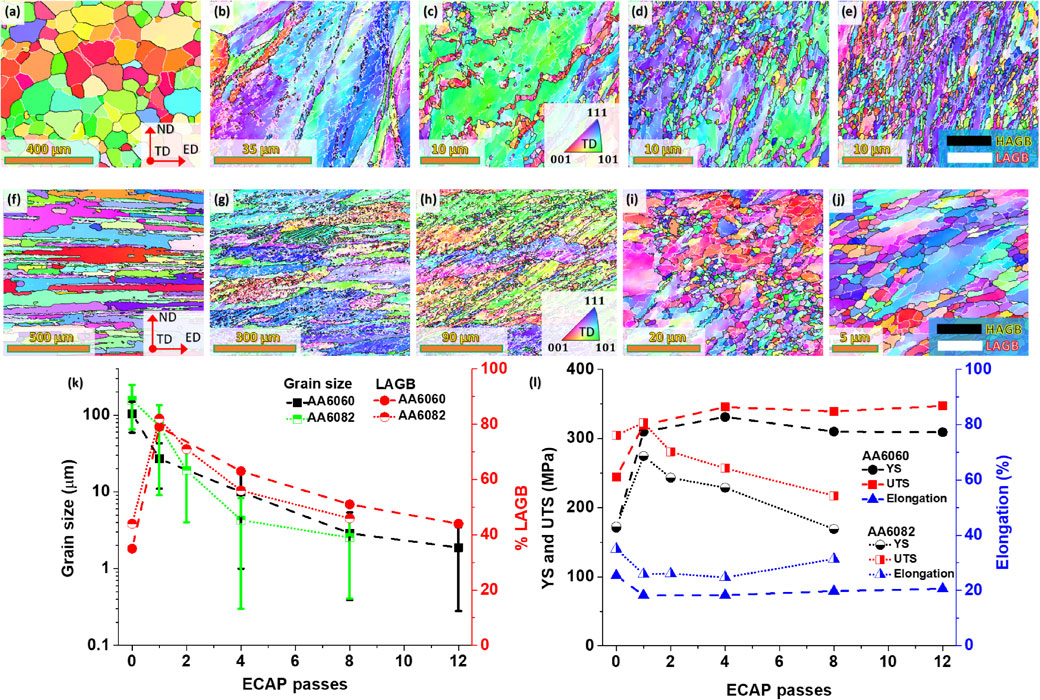
According to Fig. 4(k), the as-received AA6060 alloy shows an average grain size of ∼100 µm. In contrast, the ECAP-processed samples from one up to twelve passes exhibit fragmented and elongated grains that form an angle of approximately 25°–40° with the ED. The width of some elongated grains decreases to submicrometer scale in the eighth and twelfth passes, with sizes of 2.89 µm ± 2.5 µm and 1.88 µm ± 1.6 µm, respectively. However, the most significant decrease is obtained during the initial passes (until the fourth pass); following that, a saturation state is reached, which has also been reported for an AA6061 alloy processed by ECAP at room temperature.91)
When comparing the results gathered from the literature, a significant influence of the alloying content on the decrease of grain size can be seen. Iwahashi et al.92) found that even with more ECAP passes, there is no additional grain refinement beyond 1.3 µm for pure Al. However, for Al–1%Mg after six ECAP passes, this equilibrium grain size was 0.45 µm, while for Al–3%Mg after eight ECAP passes, this size dropped to 0.27 µm.93) Due to a significant change in stacking fault energy (SFE) and reduced recovery rates, they found that a smaller grain size was observed as Mg was added to these solid solution alloys. Regarding LAGB evolution in Fig. 4(k), it is evident that the LAGB has a high fraction generated in the first pass that reduces gradually as the number of ECAP passes increases. It can be deduced that the significant fraction of LAGBs in the early ECAP passes is due to fine dislocation structures inside the grains.
The mechanical behavior of the AA6060 alloy was also investigated, as shown in Fig. 4(l). It was observed that both YS and UTS increased up to four ECAP passes and then slightly decreased for eight and twelve ECAP passes. The highest YS (331 MPa) and UTS (345 MPa) values were obtained after four ECAP passes, which were significantly higher than those of the as-received alloy (YS (171 MPa) and UTS (244 MPa)). According to Minárik et al.,94) the increase in YS and UTS can be attributed to grain refinement and increased dislocation density. In contrast to material strength, elongation decreased from 25% to approximately 16% after the first ECAP pass. Although the ductility slightly increased from the first to the twelfth ECAP pass, it remained lower than the as-received sample. This behavior is not unique to the ECAP process and has also been observed in other alloys, such as AA105095) and AA1100,96) after accumulative roll bonding (ARB) and may be ascribed to the strain hardening capacity that depends on the microstructure and substructure, including factors such as grain size and density of dislocations.97) As the grain size decreases to ultrafine sizes, the mean free path of dislocations falls, leading to increased dislocation annihilation rates and, consequently, reduced strain hardening capacity.
For the AA 6082 alloy, the microstructures of the as-received and ECAP-processed samples at a warm temperature (250°C) are shown in Fig. 4(f) to Fig. 4(j). After solution treatment, the AA6082 alloy exhibits elongated grains with an average grain size of 156 µm, as shown in Fig. 4(k).
Elongated grains along the ED and a significant amount of LAGBs are observed after one and two ECAP passes, respectively, as shown in Fig. 4(g) and Fig. 4(h). However, the microstructure still resembles the initial elongated structure after the first two ECAP passes, with average grain sizes of 72 µm ± 60 µm and 19 µm ± 15 µm, respectively, as depicted in Fig. 4(g) and Fig. 4(h). The grain size reduction is related to many subgrains and new grain boundaries forming micro shear bands inside the elongated grains, changing the initial texture. After the fourth ECAP pass, as seen in Fig. 4(i), the microstructure is comprised of long and equiaxed grains with an average grain size of around 4.3 µm ± 4 µm. With further deformation, elongated grains surrounded by HAGBs with an average grain size of 2.5 µm ± 2 µm are seen in Fig. 4(j) for the eight ECAP passes material. According to Beyerlein et al.,98) the material texture changes can be associated with the continuous strain path modifications introduced by the route Bc, activating different slip systems between consecutive ECAP passes. Similar results have been observed in the AA7075 alloy99) and the AA2219 alloy100) after ECAP processing at 250°C, using an ECAP die of 120°.
Regarding pure aluminum, larger grain sizes result from using similar processing conditions. For instance, Subbarayan et al.101) reported an average grain size of 4 µm for pure aluminum after eight ECAP passes. These differences between the alloys and the pure material can be explained by the delay in strain relaxation within the alloy’s grain due to the influence of the dispersoids and precipitates.102) In the 6XXX family of alloys, the effective Mg content is probably the reason for the decreasing recovery rate.103) One important observation regarding grain size refinement is that the grain size reduction rate for AA6082 is slower than AA6060 at the initial deformation stages. This observation results from the processing temperature, which gives rise to a higher dislocation annihilation rate than in the room-temperature processed alloy. However, the grain size for both alloys reaches similar values after eight ECAP passes.
Figure 4(l) depicts the yield strength (YS), ultimate tensile strength (UTS), and elongation for both alloys processed at different ECAP passes. Two other behaviors are identified in this figure. For the warm-processed alloys, it is worth noting that after the first ECAP pass, YS and UTS increase together and gradually decrease until eight ECAP passes. Khelfa et al.50) described this decrease as the result of dynamic recovery and discontinuous dynamic recrystallization. However, as shown in Fig. 4(l), the ductility of all processed samples for both alloys is lower than that of the as-received condition. It is demonstrated that the AA6082 alloy loses less ductility (26.20%) after one ECAP pass than the AA6060 alloy (35.36%). After that, the alloy gradually improves its ductility up to 8 ECAP passes. As expected, increasing the number of ECAP passes at room temperature improves strength in exchange for ductility, while the opposite happens at a warm temperature. Kumar et al.104) showed that cryo-rolling the AA6082 alloy followed by warm rolling at 100°C–250°C improved the ductility. They indicated that recovery and recrystallization, which eliminate dislocations, are responsible for this improvement.
Within FCC materials, copper and copper alloys have various applications and offer functional properties. Figure 5(a) through Fig. 5(o) summarize the inverse pole figure (IPF) maps of high-purity copper and two copper alloys that were subjected to several ECAP passes (0, 1, 4, 8, and 16 ECAP passes). Figure 5(a) shows that the microstructure of annealed copper (0P) exhibits equiaxed grains with an average grain size of 7 µm, including twins. After the first pass through ECAP, the material shows substructured elongated grains with an average grain size of 15 µm. After 4, 8, and 16 ECAP passes, a bimodal microstructure is formed with large grains coexisting with an ultrafine-grained (UFG) matrix having an average grain size of 3.29 µm ± 3 µm, 1.41 µm ± 0.9 µm, and 1.47 µm ± 1 µm, respectively (see Fig. 5(p)). This developed substructure is mainly composed of subgrain bands parallel to the shear direction at approximately 45° as viewed from the transverse plane of the specimen, as shown in Fig. 5(b) through Fig. 5(e). This behavior was also observed by Xue et al.105) and Huang et al.106) in 99.97% pure copper after one ECAP pass using the Bc route. The as-received material presented 38% LAGB, which indicates that the material did not completely recrystallize. After the first ECAP pass, pure copper exhibited 80% LAGB, and after 4, 8, and 16 passes, the values were 55%, 45%, and 42% LAGB, respectively (see Fig. 5(p)).

It is worth noting that after the fourth ECAP pass, a heterogeneous microstructure is observed in which large, recrystallized grains with randomly oriented twins are present, indicating the dynamic recrystallization process, whereby twins nucleate heterogeneously at grain boundaries and grow due to the successive emission of partial dislocations from grain boundaries onto adjacent slip planes.107) This behavior is similar to that reported by Etter et al.108) in a commercial purity copper used for electrical applications, where recrystallized grains were distributed in the ultrafine matrix. After eight and sixteen ECAP passes, a heterogeneous microstructure of CGs surrounded by UFGs is observed in Figs. 5(d) and 5(e), respectively. Therefore, it can be observed that ECAP processing at room temperature induces recrystallization in pure copper.
The YS, UTS, and elongation are shown as a function of ECAP passes in Fig. 5(q). The as-received copper exhibits a YS of 88 MPa and a UTS of 300 MPa with a total elongation of 65%. After the first ECAP pass, a significant increase in mechanical strength was observed (YS = 300 MPa, UTS = 320 MPa), which caused a considerable decrease in ductility (elongation ∼20%). The maximum mechanical strength values are obtained after the fourth ECAP pass (YS = 350 MPa, UTS = 380 MPa) and remain almost stable up to sixteen ECAP passes. Additionally, it can be seen that Fig. 5(c) through Fig. 5(e) show heterogeneous microstructures with large grains immersed in a deformed, fine-grained matrix. This microstructural behavior allows for a good combination of high tensile strength and good ductility. Wang et al.109) determined that the large grains can provide strain hardening capability, resulting in high tensile ductility, while the nanocrystalline matrix can preserve the high tensile strength values. Another possible explanation for the enhanced ductility in ultrathin-grained metals is the presence of a microstructure composed mainly of high-angle boundaries and a high-volume fraction of out-of-equilibrium grain boundaries (subgrains).110,111)
Due to the low yield strength of pure copper, some alloys have been proposed. For example, copper–magnesium alloys have attracted attention due to their high yield strength and thermal conductivity. Accordingly, in this overview paper, two copper alloys with 0.2% and 0.5% of magnesium subjected to ECAP processing at room temperature are shown in Fig. 5(f) to Fig. 5(o). The as-received conditions for the CuMg0.5 and CuMg0.2 alloys indicate grain sizes larger than 200 µm after the casting process, as displayed in Fig. 5(f) and Fig. 5(k), respectively. After the first ECAP passes, large amounts of LAGB are generated for both alloys, as indicated in Fig. 5(p). This figure shows that copper alloys produce more LAGB than pure copper due to the higher density of HAGB in the as-received pure copper microstructure. Therefore, grain fragmentation occurs faster in pure copper than in the alloys until the fourth ECAP pass. From this point, average grain sizes are similar for pure copper and its alloys, reaching values between 0.2 µm–0.3 µm after eight ECAP passes, as corroborated in Fig. 5(p).
Regarding the mechanical performance, Fig. 5(q) compares the tensile strength and elongation for all the copper alloys. After the first ECAP pass, the tensile strengths are similar for all the materials, but as the deformation increases, apparent differences appear after four ECAP passes. In this context, pure copper reaches saturation after four ECAP passes, while the copper alloys after sixteen ECAP passes do not show the same plateau behavior even when the grain sizes converge to the same values for all the copper alloys. Thus, explanations focus on the alloying of the material, which generates additional hardening mechanisms like the solid solution from the magnesium atoms. Rodríguez-Calvillo et al. demonstrated that after ECAP processing, the main strengthening contributions for the CuMg0.5 and CuMg0.2 came from subgrain boundaries (GNDs), grain boundaries (Hall-Petch effect) and solid solution.66) Therefore, the magnesium addition and the SPD process can improve the tensile strength by almost 400 MPa compared to the pure copper counterpart. However, the strength-ductility continues to be mutually exclusive.
The tensile strength differences between copper and aluminum alloys are highly related to the SFE variations due to the temperature and alloy elements. For example, the warm temperature in AA6082 aluminum alloy processing does not favor the SFE reduction, indicating lower mechanical properties than the AA6060 alloy processed at room temperature. On the other hand, the addition of Mg to copper alloys reduces the SFE, improving the mechanical properties. It has been established by Valiev et al.112) that the copper strength-ductility properties can be improved in the UFG state through nanotwins, which are promoted with low SFE, low-temperature processing, and high strain rates.
3.4 HCP materials - CP titanium and magnesium alloy
To cover a broader range of properties, processing conditions, and various materials, a magnesium and a titanium alloy were deformed by ECAP at several passes and temperatures.
Figure 6 presents the main results obtained for a commercial ZK60 magnesium alloy subjected to ECAP at a processing temperature of 250°C (TH = 0.38TMP), following route Bc. The IPF map of the as-extruded ZK60 alloy (Fig. 6(a)) highlights its heterogeneous nature, with a grain size varying from 40 µm to 5 µm (average of 21 µm). The predominant orientations of the as-extruded sample are in the $(2\bar{1}\bar{1}0)$ and $(10\bar{1}0)$ planes, with variations and a small area showing orientations as (0001). The grain boundary nature of the as-extruded ZK60 magnesium alloy indicates the presence of a high proportion of LAGB (∼40%), emphasizing that its substructure is formed, in a greater proportion, from subgrains, determining better strengthening upon deformation and improved material mechanical properties.113) After the first ECAP pass, the microstructure and substructure continue to be heterogeneous, as seen in Fig. 6(b). It can be observed that the large grains begin to fragment, with low-angle grain boundaries (depicted as white lines) emerging inside these grains. Moreover, refined grains appear at the boundaries of large grains, indicating that recrystallization is taking place after one pass.114) The grains have an arbitrary orientation in the $(2\bar{1}\bar{1}0)$, $(10\bar{1}0)$, and (0001) planes.

A similar bimodal structure, with coarse elongated grains and equiaxed ultra-fine grains, was observed for the ZK60 magnesium alloy subjected to two ECAP passes (Fig. 6(c)). The heterogeneous structure can be explained as coarse grains facilitating grain boundary sliding through intragranular slip and twinning due to the limited number of slip systems in magnesium alloys, which leads to the initial deformation and refinement of grains with favorable orientations.115) It can be observed that with successive passes, the heterogeneity in the microstructure is reduced, and an equiaxed microstructure appears, which can be explained by the occurrence of dynamic recrystallization, as seen in Fig. 6(d). A further increase in ECAP passes (4 passes – Fig. 6(e)) shows a slight increase in grain size, which can be a consequence of recrystallization (dynamic, metadynamic, and static recrystallization) and rapid grain growth that can be attributed to the high processing temperature and the inter-pass time that the sample spent during ECAP.116–118)
The average grain size and LAGB distribution for each ECAP pass are illustrated in Fig. 6(f). It can be observed that the initial as-extruded ZK60 magnesium alloy has an average grain size of 21 µm ± 16 µm, but grain refinement of the magnesium samples occurs after each ECAP pass. Thus, after the first two ECAP passes, the average grain sizes were 7.9 µm ± 7.5 µm and 7.3 µm ± 7.2 µm, respectively, while the average grain sizes after the third and fourth ECAP passes were 3.7 µm ± 1.9 µm and 4.4 µm ± 2.2 µm, respectively. The grain coarsening that occurs in the last pass can be explained by the high processing temperature and inter-pass time but also due to the higher stability of the coarse grain microstructure as they present higher activation energy than refined grains.119)
Regarding the LAGB densities, the graphical representation shows a decrease in LAGB with increased ECAP passes due to the recrystallization process. This process is dynamic and appears during processing at high temperatures. In contrast, metadynamic (does not need incubation time to occur) and static (needs incubation time to start) recrystallization occur at the grain boundaries during the inter-pass time interval. The increase in LAGB density after the second ECAP pass could be due to the generation and multiplication of dislocations along the boundaries of the CGs during plastic shear deformation by ECAP. These dislocations tangle to develop LAGBs,120) as Zhao et al.121) observed, where subgrains gradually formed with the accumulation of dislocation movement, thus reducing the HAGB densities.
The YS, UTS, and elongation-to-failure of the ZK60 magnesium alloy subjected to ECAP were graphically represented in Fig. 6(g). It can be observed that the behavior of yield stress is inversely proportional to the number of ECAP passes, decreasing as the ECAP passes increase, not following the standard Hall-Petch relationship, although the grains were refined. This result can be due to the texture transition during ECAP.122) The behavior of UTS highlights an increase in the first two ECAP passes, followed by a slight decrease after the third and fourth passes. Such behavior may be explained by grain refinement and the presence of twins, which hinders the dislocation movement and improves the strength of the ZK60 magnesium alloy. Dynamic recrystallization and grain growth can explain the slight decrease in the UTS values after the third and fourth ECAP passes.123)
Elongation-to-failure values of ZK60 processed by ECAP considerably increased with the number of passes, from about 15% to ∼30% (after four ECAP passes) due to higher HAGB densities that favor grain boundary sliding. Mostaed et al. suggested that texture development is the factor that determines a decrease in both YS and UTS, concomitant with the improvement of elongation.124)
The microstructure evolution of Commercially pure Ti deformed by ECAP for 4 passes at different temperatures (TH between 0.09TMP − 0.24TMP) is presented in Fig. 7(a) to Fig. 7(e). It is possible to observe that all microstructures are of a bimodal type consisting of small and elongated grains, with an aspect ratio close to 1.8, similar to the ones reported by Suwans et al. at 400°C,125) and aligned along approximately 24° of inclination to the ED. This value is consistent with the literature when simple shear is considered for this die geometry.126) In other words, the microstructure and substructure after 4 ECAP passes are far from homogeneous, as illustrated by the LAGB fraction evolution in Fig. 7(f). The LAGB fraction slightly decreases as the temperature decreases up to the vicinity of 250°C; if the temperature is lowered, the LAGB increases again. Although a similar tendency is observed for the grain size evolution, with a minimum recrystallized grain size of 0.94 µm ± 0.39 µm obtained at 250°C, as the temperature decreases to 150°C the recrystallized grain size does not increase significantly, having an average size of 3.3 µm ± 3.25 µm. Beyond temperatures of 250°C, the average grain size slightly increases until 1.7 µm ± 0.44 µm. These observations suggest that CP titanium presents grain refinement and thermal stability at temperatures as high as 400°C after ECAP processing.

The calculated yield stress is represented in Fig. 7(g) as a function of temperature, showing two clear zones. Zone one, between 150°C and 250°C characterized by a significant increase in the yield stress as the processing temperature is lowered due to the rise in LAGB and reduction of recrystallized grain sizes. Zone two, between 250°C and 450°C, with a lesser steep yield stress increase due to the grain size growth. It should be noted that CP titanium is not as affected by the processing temperature as magnesium due to its higher recrystallization temperature.
3.5 Comparison of properties
To establish overall behaviors for the ECAP processing, Fig. 8 gathers the YS for all the previously described materials as a function of several variables. For example, Fig. 8(a) shows the evolution of the yield strength-ECAP passes. In this plot, it is clear that the main strength increments occur during the first ECAP passes (roughly below four ECAP passes), followed by less pronounced increments until a plateau state is reached in most of the materials. It also highlights that the warm processed materials, e.g., AA6082 and ZK60 magnesium alloy, reach a peak. The yield stress then decreases, describing a discontinuous dynamic recrystallization curve instead of a saturation state where continuous dynamic recrystallization dominates at room temperature. This phenomenon is linked to substructural and microstructural characteristics: 1) the high annihilation rate of dislocations promoted by the high homologous processing temperature (TH ∼ 0.37TMP), which gives rise to heterogeneous microstructures, even grain growth for the ZK60 alloy, and 2) the precipitate coarsening that lowers the yield strength in both alloys. According to Figueiredo et al.,127) processing temperatures ranging between 0.37TMP < T < 0.5TMP are considered to be moderate, where grain refinement and softening can occur. Conversely, other HCP materials like CP titanium suggest good thermal stability after four ECAP passes processing at several temperatures ranging between 150°C and 400°C (TH between 0.09TMP − 0.24TMP), and a difference between the lowest and the highest tested temperatures of only ∼50 MPa for yield strength.

Regarding the steels and copper alloys, there is an apparent effect of the alloying elements producing larger tensile strengths than the pure base element counterpart due to the SFE decrease. For example, the 1020 low-carbon steel, due to its higher carbon content, reached higher tensile strength than Armco® Fe with a lower amount of deformation. Similarly, duplex stainless steel characterized by high contents of Cr and Ni produced tensile strengths over 1200 MPa with a UFG biphasic microstructure of ferrite and austenite that did not go through any phase transformation at 250°C, showing good thermal performance. The alloying effect is also observed in copper alloys, where adding small amounts of Mg improves the alloy’s strength compared to pure copper due to the grain and precipitation refinement of the ECAP process at room temperature.
Figure 8(b) shows the materials’ strengthening effect, which plots the YS against the inverse mean square root of the grain size. Thus, the grain refinement potential of duplex stainless steel is confirmed, allowing it to reach similar grain sizes after two ECAP passes to Armco® Fe after sixteen ECAP passes, as suggested by the Hall-Petch equation:1,2)
| \begin{equation}
\sigma_{Y} = \sigma_{0} + K_{\textit{HP}}d^{-1/2}
\end{equation}
| (3) |
where σ
0 is the friction stress,
KHP is the Hall-Petch constant and
d the average grain size.
The Hall-Petch or grain boundary strengthening mechanism also confirms the superior hardening capacity by dislocation accumulation of 1020 low carbon steel over Armco® Fe at the same plastic deformations. This strengthening effect is reflected in the steep Hall-Petch slopes, like the copper alloys in regard to the pure copper counterpart. In copper alloys, this effect has to do with precipitates and dislocation interactions. SPD also refines the size of the precipitates, which in turn renders the dislocation motion more difficult, increasing the dislocation density and the overall hardening. Therefore, even when the grain sizes of the as-cast copper alloys were more than two orders of magnitude larger than the pure condition (see Fig. 5(f) and Fig. 5(k)), the alloying effect favored faster hardening.
Moreover, aluminum alloys show lower hardening capacities than copper due to aluminum’s high stacking fault energy, which causes the material to deform by dislocation emissions with a strong tendency to cross-slip. This behavior at the nanometric level causes very low dislocation accumulation and hence low strain hardening rate.128) It is worth mentioning that SPD can produce nanosized particles in aluminum alloys like the 6XXX series, as corroborated by Valiev et al.129) In this context, the AA6082 alloy should have also experienced a precipitate coarsening due to the moderate homologous processing temperature instead of a precipitation refinement.
HCP materials’ hardening behavior seems less evident due to their limited slip systems at room temperature, which makes using temperatures for ECAP processing necessary. As such, ZK60 magnesium alloy presents neglectable hardening, even softening due to the grain growth observed in Fig. 6. In this case, the low melting temperature of magnesium (650°C) facilitated the static and dynamic recrystallization during the heating and processing of the sample. However, 250°C did not affect in the same way the CP titanium (melting temperature 1668°C), and as such its strength after ECAP processing at 400°C was even higher than the CG and the heterogeneous microstructure of the pure titanium processed by equal channel angular sheet extrusion (ECASE) at room temperature using a 150° die reported by Muñoz et al.52) In terms of hardening contributions, it has been demonstrated that the main strengthening contributions in the different systems come from the LAGB, HAGB, solid solution, precipitation, and Peierles-Nabarro stress.130) Thereby, it is observed from Fig. 2 through Fig. 7 that all the processed materials presented contributions from LAGB even after sixteen ECAP passes and warm processing temperatures, suggesting more strength improvement if more LAGB can be converted into HAGB.
The grain refinement produced by the ECAP process increases the strength of metallic materials, decreasing strain hardening, a property that depends on the microstructure and substructure nature (i.e., grain size, dislocation density, and their distribution) instead of the crystal structure (slip systems available). Thus, this subject is in the spotlight of the research community since ductility is a significant issue of UFG materials.4,131) Figure 8(c) proves that the highest yield strengths correspond with the lowest homogeneous plastic deformations and the largest ductility values with the smallest strengths, meaning that no materials in the as-received or ECAP-processed conditions reach a strength-ductility balance. Valiev et al.112) confirmed that strain-hardening mechanisms associated with dislocation accumulations are less effective inside the ultrafine grains.
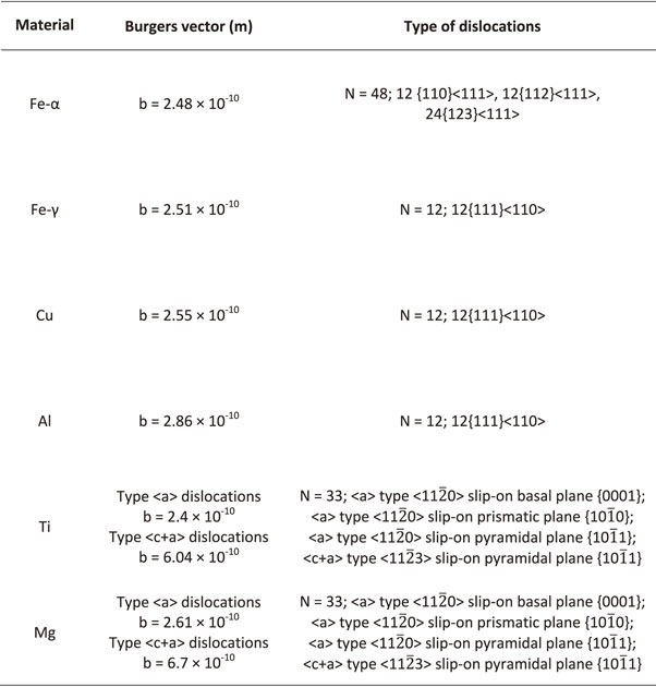
With regards to the CG as-received conditions, the efficient dislocation slip mainly controls the deformation mechanism. For example, the Armco® Fe (48 slip systems) and the copper-based alloys with low stacking fault energy, which makes the twinning deformation mechanism possible, showed the largest ductility values and excellent plasticity. Then, the as-received conditions of aluminum and magnesium indicate lower ductility values than those mentioned above due to the high stacking fault energy and the limited slip systems, respectively. On the other side of Fig. 8(c), in the UFG regimen, the high strength and low ductility are due to the restricted space for the dislocation motion, leading to inefficiency in storing dislocations inside the ultrafine grains. A low strain hardening rate manifests reduced ductility due to the annihilation of mobile dislocations. Balasubramanian et al.130) and Valiev et al.112,132) have suggested several approaches to improve the ductility of UFG materials following mechanical and microstructural-based strategies. According to the Considère and Hart criteria, the mechanical strategies involve increasing the strain hardening rate and the strain rate sensitivity. Moreover, the microstructural strategies seek for the smart design of microstructures like bimodal grain sizes, high density of twins, and heat treatments after SPD processing. In this context, new investigations solve this strength-ductility paradox using heterogeneous materials (HM). These materials look for synergy between strength-ductility with microstructures made up of CG and UFG grains that create new deformation mechanisms due to the hetero-deformation state across the interphases between the hard and soft regions.133,134)
Grain fragmentation and its saturation after several ECAP passes depend on the GNDs’ evolution. Figure 9(a) illustrates the average GND dependency on the number of ECAP passes for all the described materials. This plot reveals that the most significant GNDs increment are produced at deformations no larger than true plastic strains of 4 (red-shaded zone), in good agreement with the high LAGB fractions indicated in Fig. 2 to Fig. 7. Thus, the overall amount of GND comes from dislocations that control the lattice curvature and the dislocations that build up misorientations through the walls of subgrains as a CG fragmentation mechanism to compensate the lattice curvature. As a result, the LAGB fraction grows as further information is applied until a peak is reached (LAGB peaks occur between the first and second ECAP pass) and then start their transformation into HAGB. When the HAGB fraction becomes dominant, the GND increments slowly until it levels up around a particular value, indicating slow grain fragmentation (yellow-shaded area). Thus, few amounts of GNDs form new LAGBs as the lattice curvature is smaller than in the CG condition, suggesting that under the ECAP deformation mode, the grain size reduction becomes slow after four or five ECAP passes, which is almost negligible due to the low possibility for GND grouping inside the UFG. GND evolution also confirms that high SFE materials like aluminum alloys presented the lowest increments because they are more prone to recovery and recrystallization phenomena and this is reflected in the lower strength increments, as shown in Figs. 8(a) through 8(b).

It should be noted that more type ⟨a⟩ GND is obtained through the basal {0001} and prismatic $\{ 10\bar{1}0\} $ slip system in HCP materials like titanium and magnesium. Conversely, one order of magnitude under, we find ⟨c + a⟩ GNDs in the pyramidal $\{ 10\bar{1}1\} $ slip system due to its most considerable critical resolved shear stress. These materials also highlight constant and large GND densities, which indicates that further grain size reductions can be achieved by either reducing the processing temperature or changing the deformation mode. Zehetbauer et al.135) demonstrated that SPD processes with high hydrostatic pressures reduce the dislocation annihilation rate, allowing the obtaining of finer grain sizes.
Figure 9(b) plots the dependency between the average GND and the average grain size. In this plot, the GND densities increase as the grain sizes decrease. The most significant increments are obtained from the as-received state to average grain sizes of 1 µm (approximately two orders of magnitude from 1012 m−2 to 1014 m−2). Below 1 µm, most of the average GND densities of metallic materials processed by ECAP tend to converge around 1015–1016 m−2. Thus, analyzing the average values for all the materials, a logarithmic relationship describes the GND densities as a function of the grain size in the UFG regime.