Abstract
The interactions between edge dislocations and ⟨112⟩-axis symmetric tilt grain boundaries (GBs) in Al, Cu and Ni were analyzed by molecular dynamics simulations. Absorption, transmission and pile-up were all observed while absorption is the dominant phenomenon, especially in Al. The leading partial dislocation was spontaneously absorbed into the GB without any resistance, as was even the trailing partial dislocation in Al for the high-energy GBs. However, for all the GBs in Cu and Ni, further external shear loading was necessary to trigger the defect interactions. Σ11A GB requires the largest shear stress to trigger the absorption of trailing partial dislocation, and the other GBs follow a general trend that the critical shear stress would decrease as the GB energy increases since the low-energy GB shows a more stable state. For the most stable GB of Σ11A in Al, Cu, Ni, and the further addition of Au and Pd, the critical interaction shear strain to trigger the interaction is proportional to a physical parameter which is based on the difference between the unstable and stable stacking fault energies.

1. Introduction
The advancement of manufacturing technology has led the internal texture size of metals until reaching nanoscale, resulting in a significant increase of the density of grain boundaries (GBs).1–3) According to the empirical Hall-Petch relation, the strength and plasticity of metals are greatly influenced by size of the grains and can be illustrated by the interactions between dislocations and GBs, as the plasticity is mainly mediated by the motions of the dislocations.4–7) As observed in experiments and simulations, when a dislocation impinges on and interacts with a GB, there are various possible outcomes which may be influenced by crystalline orientations of the adjacent grains, the type of dislocations and local microstructural attributes of the GBs.8,9) For example, 1) the dislocation can be hindered by the GB and piled up before it, improving the strength of the material but deceasing its ductility;1,10) 2) the dislocation is absorbed by the GB and the local microstructure of the GB would change, which may affect the interaction with the subsequent dislocation;11–14) 3) the dislocation transmits across the GB and slips in the adjacent grain, mediating the plasticity;15) 4) the dislocation may be reflected back into the original grain by the GB. The residual dislocation may appear on the GB and a new dislocation may be emitted from the GB into the grain after the foregoing interaction to conserve the Burgers vector.16,17)
Each interaction mechanism is reflected in the mechanical properties of the nanomaterial. For example, in copper (Cu), the coherent twin boundary (CTB) impedes the lattice dislocation motion, making intragranular movement of the dislocations more difficult. Consequently, the strength significantly increases when the density of CTBs increases, especially compared with the coarse grain Cu.18) On the other hand, the ductility can also be improved in Cu with the high CTB density because the dislocation may also pass over the CTB, which has been confirmed and observed in experiments and atomistic simulations.1,14,19,20) If absorption is dominant in the dislocation-GB interactions, such as for the hydrogen accumulated GB in Ni, the transmission, nucleation and reflection are suppressed and vacancies are easier to generate which facilitates H embrittlement.21,22) Clearly, the GB can significantly affect the mechanical behaviors of the metals so that various preparation processes have also been exploited to create various beneficial GBs. In plenty of experiments, the low-angle GBs, twin boundaries and relaxed GBs were fabricated to maintain a considerable strength, hardness and thermal stability for the nanograined metals since these GBs own relatively low energy and prevent the grain coarsening at room or elevated temperature.23–26) Although it is widely accepted that GBs can impede the dislocations, relying solely on such a general concept does not allow the design of stronger and tougher materials. There is a pressing need for a thorough understanding of the detailed mechanisms of interactions between dislocations and GBs.
Kondo, et al. revealed the geometric effects and local structural stabilization effects which simultaneously influence the interaction processes between the individual lattice dislocation and large/low angle GB through the in-situ transmission electron microscopy (TEM) nanoindentation experiments.27) Despite being really vivid and valid, it still needs further study on the numerous GBs with more complicated local structures or other atomic arrangements. This can be approached by molecular dynamics (MD) rather than experiments when considering economic benefits and difficulties in specimen preparation. Using MD, Sangid, et al. proposed the control-box method to measure the energy barrier which triggered the defect interactions for the different ⟨110⟩-axis symmetric tilt GB, and established the relation between that energy barrier and static GB energy.28,29) The partial dislocations were generated by the void in a sandwich-like structure and the energy barriers were sensitive to the size of the control box. To investigate the interactions between an individual perfect dislocation and GBs and simultaneously consider the different potential slip planes on the GBs, Li, et al. generated a perfect edge dislocation rather than partial dislocation through Volterra’s displacement field.30) They showed that the critical interaction shear stress would decrease if the GB had a higher static GB energy in Cu, providing a straightforward evidence and support for the preference of using low energy interfaces, such as foregoing low-angle GBs, to maintain a good mechanical performance at a certain temperature. However, whether this trend can be extended to the other materials still needs further research, which is also one purpose of the present work. Namely, we need to determine the most suitable GB structure which can give the highest strength.
Besides the local atomic arrangements and morphology of the GBs,31–35) the interactions between dislocations and GBs may be altered by the materials and hence the strength or plasticity. Jin et al. comprehensively investigated the interactions between the screw dislocation and the CTB in Al, Cu and Ni.19) The incident screw dislocation would be spontaneously absorbed by the CTB in Al without any resistance and the interaction would cause the CTB to migrate for one layer of atoms. Alternatively, in Cu and Ni, the screw dislocation would transfer across the CTB and slip into the adjacent grain. They proposed a stacking fault energy-based parameter R and “twin fault nucleation energy” based parameter R′ to explain the interaction mechanisms and reflect the chemical nature of the different metals. Similarly, Chassagne, et al. proposed a linear relationship between critical interaction shear stress (CISS) and a non-dimensional parameter in the interaction between dislocations and CTBs in typical face-centered-cubic (fcc) metals with an exception for Cu.36) This parameter is related to the Burgers vector of partial dislocation and the static stacking fault energy. On the contrary, Celebi, et al. found a strong positive correlation between the CRSS and the unstable stacking fault energy, but a poor correlation was associated with intrinsic stable stacking fault energy in fcc pure metals or Ni–Ti, Ni–Co alloys.37) It is worth noting that the unstable stacking fault energy was also used to represent the resistance to emitting a dislocation from the crack tip or one factor that determined the tensile strength for the defect-free twin nanowire.38,39) Apparently, these energy-based physical parameters can reflect the relationship between the CISS and material type for screw dislocation and CTB interactions, although there are some exceptions. Naturally, we can also raise a question that whether there are similar energy-based parameters that can be used to reflect the CISS for the interactions between an edge dislocation and general GBs in fcc metals. This is another purpose we are trying to investigate in this work.
In this study, in order to address these questions, we first created a sandwich-like structure which contained one edge dislocation and one ⟨112⟩-axis symmetric tilt GB. Plenty of MD simulations were conducted to investigate the influence of GBs and materials.
2. Simulation Methodology
The whole setups are divided into three parts: 1) the calculations of static GB energies; 2) the calculations of stable and unstable stacking fault energies; 3) the interaction of the incident edge dislocation and GB.
Different ⟨112⟩-axis symmetric tilt GB structures with various coincidence site lattice (CSL) values and misorientation angles were generated using Python code.40) To find the most stable GB with the lowest static GB energy for the given CSL value, more than 50 GBs were generated through the rigid in-plane displacement method and subjected to molecular static simulations based on the conjugate gradient (CG) method.30) Periodic boundary conditions were applied in all three directions, resulting in two GBs in the model: one was set in the middle parallel to the boundary surface and the other was intersecting the boundary surface. Such setup refers to the previous researches and treats the twin system as a representative volume unit to reflect defect interactions.11,13,14,47)
To calculate the stable and unstable stacking fault energies, the conventional method involves rigidly displacing the half of the original perfect lattice along the ⟨112⟩ direction with several sub-steps.41) However, the accuracy and precision depend on the resolution of the sub-step size. To overcome this drawback, nudged elastic band (NEB) method was adopted to obtain the generalized stacking fault energy curve for different materials.13,42–44) To this end, two atomic structures, so called initial replica and final replica, are necessary. The initial replica was set up as the perfect lattice with the orientation of [112] in X, $[11\bar{1}]$ in Z and $[1\bar{1}0]$ in Y. The final replica was constructed by rigidly displacing the upper half and lower half of the initial replica by approximately a0/6[112] in opposite directions along X, respectively, so that a twin fault appeared in the final configuration, where a0 is the lattice constant. NEB method generates a series of intermediate replicas that match the minimum energy path (MEP) of the formation process, and the stable and unstable stacking fault energies can be found by the peak and saddle point. Periodic boundary conditions were used in the X and Y directions. The quick-min method was used for the damped dynamics minimizer with a spring constant of 1 eV/Å and a total of 36 replicas were used to calculate the MEP.
To realize the interaction between a edge dislocation and GB, some bicrystal models created to calculate the GB energy were duplicated and scaled to an appropriate size and rotated to the desired orientations, which is $[1\bar{1}0]$ for dislocation slip direction in X, $[\bar{1}\bar{1}1]$ for slip plane normal in Z and [112] for edge dislocation line in Y. More than 11 different GBs were selected and the geometric information is given in Table 1. The whole model was then cut and reshaped to a regular hexahedral model, as shown in Fig. 1, and the domain sizes were about 60 nm in X, $10\sqrt{6} a_{0}$ in Y and 22 nm in Z for all the materials. The model size was carefully verified for Σ11A of Cu, as a representative example, and showed small fluctuations in the CISS within 50 MPa when it ranged from 44 nm to 60 nm in X and 16 nm to 22 nm in Z. A single perfect edge dislocation was inserted into the parent grain using Volterra displacement field and ATOMSK.45) The position in Z-direction of the edge dislocation was adjusted to match different impacting points and slip planes for different GBs, due to local atomic arrangement’s influence on the interaction mechanisms. For example, 6 independent potential slip planes exist for Σ11A, as shown in Fig. 1. A perfect dislocation would dissociate into two partial dislocations after the energy minimization. Periodic boundary condition was applied in Y direction to mimic an infinitely long dislocation line and GB plane. Atoms in the upper and lower 10 Å regions were set as the rigid parts in order to apply the external load, in which way the whole system is like a sandwich model and has been widely used in many other researches.31,36,46–48) To apply an external shear load and drive the dislocation towards GB, a velocity of 0.03 Å/ps was applied in opposite directions on the X-axis to the upper and lower rigid regions, respectively, resulting in a strain rate of approximately 108/s. The canonical ensemble (NVT) was used for MD simulations and the temperature was kept around 0.1 K to suppress any thermal perturbations that might affect the activated processes of the dislocation itself.19,22) Atomic configurations were sampled every 2 ps to generate the animations.

Table 1 Crystallographic details and GB energies for Al, Cu and Ni.
All the MD and NEB calculations were implemented by the large-scale atomic/molecular massively parallel simulator (LAMMPS) code.49) Embedded-atom-method (EAM) interatomic potentials are used in the MD simulations for Al, Cu and Ni, which were developed by Mishin et al. and show good agreement with the experiments for some fundamental physical parameters.50–52)
3. Results
3.1 Grain boundary energy map
The static ⟨112⟩-axis GB energies EGB were calculated according to the formula EGB = (Es − N · Ec)/(2A). A is the area of GB, Es represents energy of the bicrystal, Ec is the cohesive energy per atom determined by EAM potential and N is the number of atoms in the system. The corresponding relationship between GB energies and misorientation angles is depicted in Fig. 2. Obviously, irrespective of the materials, there are two local minima, corresponding to Σ11A (62.96°) and Σ35B (122.88°), respectively. There are three peaks located around 40°, 100° and 140°. Numerically, the GB energies range from 150 mJ/m2 to 496 mJ/m2 for Al, from 309 mJ/m2 to 958 mJ/m2 for Cu, and from 533 mJ/m2 to 1598 mJ/m2 for Ni. It is worth noting that the three peaks of Cu and Ni are relatively steep, whereas the latter two peaks of Al are much more gradual and even the peaks are not so obvious. This gradual trend may also have an effect to the defect interactions.
3.2 Generalized stacking fault energy curves
The deformation mechanism can be strongly influenced by stable intrinsic stacking fault energy γSF (SFE) or unstable stacking fault energy γUSF (USFE), especially for dislocation related mechanism. In the high SFE metals, the dominant deformation mechanisms are dislocation glide and cross-slip, while twinning is the primary deformation mechanism in the low SFE metals.53,54) Moreover, Rice proposed that the material with the higher γUSF had the higher resistance to the dislocation emission from the crack tip.38) Such conclusion has also been extended to dislocation emission from the GB by Asaro and Suresh.55) Therefore, in order to establish a quantitative relationship between the defect interactions and their strength, it is necessary to first calculate these critical physical parameters for the materials.
According to the method in Chapter 2, NEB method gave the generalized stacking fault energy curves (GSFEC) for Al, Cu and Ni, as shown in Fig. 3. Figure 3(a) is the MEP for the generation process from the defect-free perfect crystal to the stacking fault state. GSFEC also has two peaks, corresponding to Configuration II of unstable stacking fault (USF) and Configuration IV of unstable twin fault (UTF), as shown in Fig. 3(b). Two plateaus corresponding to Configurations III and V represent the most common crystallographic defects: intrinsic stacking fault (ISF) and extrinsic stacking fault (ESF). The specific defect energies of SF and USF for different materials are summarized in Table 2. Apparently, from Figs. 3(a) and 3(b), it appears that the system should overcome the energy barrier of USFE to produce the ISF from a perfect crystal and vice versa. This corresponds well with the conclusion of Rice,38) Asaro and Suresh,55) as mentioned before, and physically explains their kernel. Another interesting point is that a material with the higher USFE relatively has the higher SFE, as shown in Fig. 3(a) and Table 2. And also, you can find that the difference between γUSF and γSF in Al is much smaller than the others. However, the deformation behavior is usually associated together with the SFE in some experiments,56,57) probably because the SFE is easier to measure than USFE in experiments. As discussed later, the present work is focused on the difference (γUSF − γSF) and thus the dimensionless parameter of (γUSF − γSF)/μbp are calculated at the last column in Table 2.
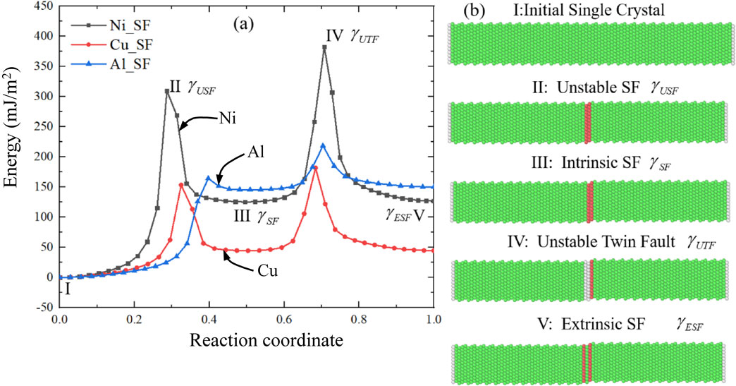

Table 2 Fundamental physical parameters for different materials calculated by various EAM potentials. bp is the magnitude of the Burgers vector of partial dislocation, μ is the shear modulus. The suffix behind element means the author of the EAM potential.
As mentioned above, 11 GBs with a misorientation angle from 34.05° to 122.88° were selected in the present work. A general summary of the results of defect interactions can be found in Table 3, including the category of interacting events and the CISSs that triggered the absorption of trailing partial dislocation (TPD). When the incident edge dislocation impinged on the GB, absorption, transmission and pile-up were all observed in these defect interactions. More specifically, as several different independent slip planes exist for a given GB, two or more events could be observed and the CISS was also changed according to the impacting points due to the different crystallographic morphology. From an engineering point of view, the slip plane with the lowest CISS will determine the interaction strength of this GB, so in the present work, the CISS in Table 3 is the minimum value of the strength of all slip planes. Recall that if the minimum CISS is 0 MPa, we take the second smallest value. And if all the values are 0 MPa, the symbol “/” is used in Table 3. The succeeding loading after the absorption may induce the different event like emission of dislocation from GB and so no. Thus, the last column in Table 3 show the stress necessary to that event as reference, of which some are equal or some are much larger.

Table 3 Crystallographic and mechanical details of the edge dislocation - GB interactions. For the interaction events, “A” stands for normal absorption, “SA” for spontaneous absorption, “T” for transmission and “P” for pile-up. Recall that nonzero CISSs of Al except Σ11A are all ones from the second weakest impact points, not from the weakest because they are all 0 MPa. Also, as of Σ73A and Σ77A, the data have the two kinds of sets because of the different event dependence to the slip plane.
In the following sections, several representative phenomena are presented in detail.
3.3.1 Spontaneous absorption without resistance and normal absorption with resistance
After the first energy minimization, the inserted perfect dislocation dissociated into two partial dislocations which was bonded by a stacking fault, as shown in Fig. 1. If the initial insertion position was close enough to the GB, the leading partial dislocation (LPD) of αC was absorbed by the GB during the energy minimization stage, even though no external load was applied. This can also lead to the characteristic phenomenon, where the LPD of αC was immediately absorbed by the GB as soon as it came into contact with the GB. This is regarded as the spontaneous absorption process of LPD (denoted as “SA” in Table 3). This also indicates that a CISS between the edge dislocation and the ⟨112⟩-axis symmetric tilt GB is not determined by the LPD, but rather by the interactions between the TPD and the GB.30) Such a phenomenon was valid for all the materials investigated in this work.
Taking Σ11A as an example for the absorption, as shown in Figs. 4(a) and (b), Σ11A GB plane has a regularly arranged plate interface with 6 independent potential slip planes in Fig. 1. The extended dislocation was first placed away from the GB and the free surface so that it would not be attracted and does not move to either side without the external shear loading. Increasing the load drove the dislocation towards the GB. Once the LPD touched the GB, it was immediately absorbed by the GB and a subtle reduction of the stress indicated such spontaneous absorption process, as shown by Point I in Fig. 4(a) for Al, Cu and Ni. However, the phenomena for different materials were diverged when the external load was further increased. For Ni, the misfit step appeared on the Σ11A while the TPD was still repelled in Fig. 4(b). The misfit step was formed by the migration of the GB and can be identified on the strain-stress curve at point II in Fig. 4(a). Nevertheless, in Al, no misfit step was generated on the GB plane until the TPD was absorbed by the GB. Eventually, the entire extended dislocation was absorbed by Σ11A at about 770 MPa, 1330 MPa and 1920 MPa for Al, Cu and Ni, respectively. Simultaneously, several misfit steps and a tumor-like mass were generated at the impinging region to mediate and conserve the Burgers vector. For Σ11A, CISS and the corresponding phenomenon did not change significantly for all the tested materials, regardless of the different slip planes, because the atomic arrangement of Σ11A is relatively regular.

For the other GBs with much more complex structures, such as Σ73A, the obtained event is strongly dependent to the slip plane. Table 3 shows the two kinds of Σ73A. The upper case produces all the transmission (“T”) and the lower does absorption (“A”). The CISS and the stress for each event were changed due to the different event. It is the same in the case of Σ77A in Table 3.
3.3.2 Pile-up
From a conventional perspective, the GB is recognized as the obstacle to the movement of the dislocations, hence pile-up is one of the most fundamental and common phenomena in the defect interactions. Among the tested 11 GBs, pile-up was observed in Σ35A and Σ21A, as shown in Table 3. All the 5 tested slip planes in Ni supported pile-up with the LPD being repelled by the GB from the beginning, rather than spontaneously absorbing the LPD as in the other GBs. Such repulsion effect did not change with increasing the external shear load, and the TPD gradually approached the LPD, reducing the width of the SF as the external load increased. As of Σ21A in Cu, the extended dislocation pairs may even be recompressed into the perfect dislocation if the external load reaches a certain level, but generally GB might prioritize emitting new defects to the either side of grains due to the excessive external load.
However, even for the same GBs that preferred the pile-up, there are still some differences among Al, Cu and Ni. All the 5 tested slip planes in Σ21A gave the pile-up in Ni, but only 3 out of 5 slip planes supported pile-up in Cu and the other two slip planes gave the normal absorption with CISS of 370 MPa. Moreover, none of the 5 slip planes gave pile-up in Al, but rather normal absorptions were observed around 60 MPa for 3 slip planes and the rest 2 slip planes gave spontaneous absorptions. The further consideration on Al will be done in the following discussion.
3.3.3 Transmission
Dislocation penetration through the GB can, to a certain extent, mediate the deformation and increase the ductility of the material. As observed in experiments,1) dislocation penetration through twin boundaries also increases the plasticity of nano-twinned copper. Among the tested 11 GBs, transmissions were observed in the cases of Σ73A and Σ77A GBs. Figures 4(c) and (d) shows the transmission event after the interaction to Σ73A. Apparently, the morphology of Σ73A shows a zigzag type interface, which exhibits a wavy and undulating shape with grooves. A similar shape was also observed in Σ77A. After the spontaneous absorption of the LPD, as shown by Point I in Fig. 4(c), the width of SF continued to shrink and the TPD was getting closer to the GB plane when the external shear load increased. During this process, the grooves near the impinging region became shallower. When the shear stress reached around 1750 MPa at Point II in Fig. 4(c) in the case of Ni, the TPD was completely absorbed into the GB. To trigger the transmission, the shear stress needs to be above 2850 MPa, as shown by Point III in Fig. 4(c). Before that, new dislocation embryos were slowly generated in the impinging region, and when the stress reached the critical value, a complete perfect dislocation was released into the adjacent grain, as shown in Fig. 4(d), with a Burger vector of $a_{0}/2[10\bar{1}]^{T}$, where the superscript T denotes that this Burgers vector applies to the Millar index of the adjacent grain. The residual defect was left on the GB and corresponding Burgers vector can be calculated by
| \begin{equation}
b_{\textit{parent}} = b_{\textit{residual}} + Rb_{\textit{adjacent}},
\end{equation}
| (1) |
where bparent is the Burgers vector of the incident dislocation in the parent grain, which is equal to $a_{0}/2[1\bar{1}0]$. badjacent, equal to $a_{0}/2[10\bar{1}]^{T}$, is transferred to match the coordinate system by the rotation matrix R. For the ⟨112⟩-rotation axis and 69.97 rotation angle for Σ73A, R become as follows.
| \begin{equation}
R =
\begin{bmatrix}
\dfrac{33}{73} & \dfrac{64}{73} & \dfrac{-12}{73}\\
\dfrac{-48}{73} & \dfrac{33}{73} & \dfrac{44}{73}\\
\dfrac{44}{73} & \dfrac{-12}{73} & \dfrac{57}{73}
\end{bmatrix}
.
\end{equation}
| (2) |
Thus, the Burgers vector of the residual dislocation left on the GB is a0/148[28 20 13]. It is worth noting that the stress did not significantly decrease when the TPD was absorbed, as shown by Point II in Fig. 4(c). However, the stress would dramatically drop when the new dislocation was emitted from the GB and it will raise again when the dislocation escapes from the free surface, as shown by the black line in Fig. 4(c) for Al. Because there was no dislocation in the system and the bicrystal would deform elastically again.
4. Discussions
4.1 Relationship between CISS and GB energy
Figure 5 shows the relations between the CISSs and the static GB energies of Al, Cu and Ni. In terms of global trend, all the data points of Al, Cu and Ni illustrate an obvious tendency: the higher the GB energy, the lower the CISS. The CISS for Σ11A is the highest of all the tested materials since its energy is the lowest and Σ11A has a relatively well-arranged atomic structure. However, there are still many details that need to be explained separately. Focusing on Cu and Ni first, Fig. 5(a) gives the relation between CISS and GB energy in Cu, where the most of the data points lie along the visual guide straight line. Compared to Fig. 5(b) which represents Ni, the data points in Fig. 5(a) are more densely arranged, reflecting a more obvious trend. You can see that there is no point representing Σ21A in Fig. 5(b) because only the pile-up was observed in Ni and it was excluded. Another interesting point is that although the GB energy and even the CSL values are almost the same for Σ35A and Σ35B, the CISSs of these two GBs are very different. The apparent distinctions also exist in the interaction mechanisms. For Σ35B, all the tested 7 potential slip planes gave normal absorptions for the defect interactions. On the contrary, 6 out of the 12 tested slip planes in Σ35A showed the pile-up phenomena and the rest 6 slip planes showed normal absorption. This suggests that GB energies can only represent certain trend, but more accurate predictions of CISS may require the other parameters, such as the local atomic arrangements of the GBs.
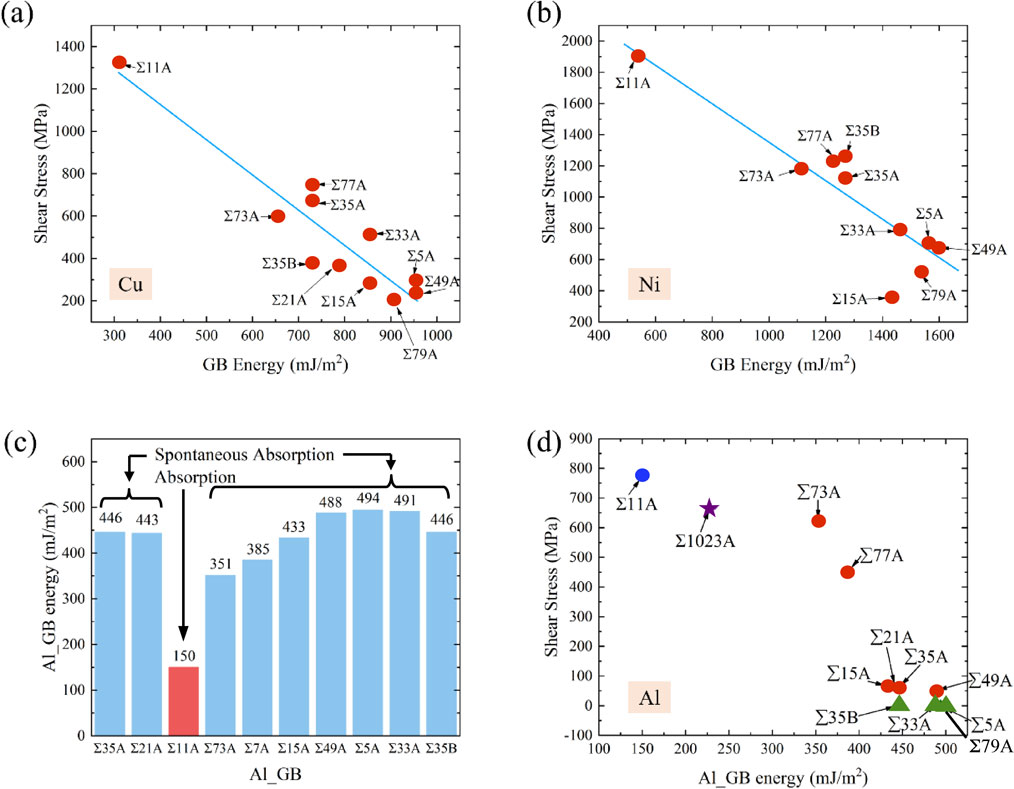
For Al, as mentioned before, most of the GBs provided spontaneous absorptions, with the exception of Σ11A. As shown in Fig. 5(c), most of the events represent the spontaneous absorptions for the GBs with higher GB energy except only the normal absorption of Σ11A. It is obvious that if we are only interested in the weakest impact point on the boundary as is the case with Cu or Ni, then the CISS of all boundaries except Σ11A becomes just 0 MPa. This is not conducive to clarifying the relationship between CISS and GB energy. Therefore, the circle points in Fig. 5(d) show the relationship between the second weakest impact point CISS and the GB energy of all the GBs except the Σ11A. Surprisingly, even for the second weakest impact point, CISS still decreases with increasing GB energy, which is similar to the trend for Cu and Ni. It should also be noted that all slip planes of Σ5A, Σ33A, Σ79A and Σ35B have given only the spontaneous absorptions so that their CISSs remain at 0 MPa, as shown by the four triangles in Fig. 5(d). Apparently, such a large amount of spontaneous absorptions is unique to Al and is rarely found in Cu and Ni. This phenomenon is probably related to the energy state of the GBs. Although the GB energies of Cu and Ni are mostly higher than that of Al, it can be seen from Fig. 2 that the GB energy map of Al is significantly gentler than those of Cu and Ni. This indicates that the energy of each GB of Al is relatively close to its peak point (∼500 mJ/m2). While the previous trend indicates that the higher the GB energy, the lower the CISS, i.e., the closer the energy is to the peak point, the lower the CISS. A flat GB energy map, on the other hand, indicates that most GBs are in relatively high energy state compared to the peak point. Therefore, a large number of spontaneous absorption phenomena may occur in Al, especially for the three high energy GBs of Σ5A (495 mJ/m2), Σ79A (496 mJ/m2), Σ33A (491 mJ/m2) and Σ35B (447 mJ/m2). For Cu and Ni, the GB energy maps tend to change significantly, and therefore the CISS of Cu and Ni might be relatively more pronounced.
To further prove this conjecture, we additionally calculated another GB of Σ1023A with the misorientation of 64.84° and the GB energy of 229 mJ/m2, which is much lower than the other GB energies. Σ1023A GB is similar to Σ11A that has the misorientation of 62.96° and the GB energy of 150 mJ/m2, but Σ1023A is a zigzag type GB. There are more than 30 independent potential slip planes for Σ1023A and 8 of them were randomly selected to calculate the CISS. In conclusion, all the tested slip planes supported normal absorptions and the weakest impact point on GB gave the CISS of 660 MPa, as shown by the asterisk in Fig. 5(d). It is clear that a relatively low GB energy, such as the energies of Σ11A and Σ1023A, ensures the occurrence of normal absorptions, but a rather high-energy GB favors spontaneous absorption and inhibits normal absorption. At the same time, the addition of the Σ1023A does not change the previous trend, but even enhances it, i.e., the higher the GB energy, the lower the CISS.
4.2 Influence of stable and unstable SFEs on defect interactions with Σ11A
In the section 4.1, the relationships between GB energies and CISS are determined. The foregoing trend describes the influence of the microstructures and local atomic arrangements on the CISS. However, for the same structure, such as Σ11A which material has the highest strength, what kinds of physical parameters are relevant to the trend? This is the question that needs to be addressed in this section.
Chassagne, et al. provided a comprehensive investigation on the screw dislocation - CTB interactions in Al, Cu and Ni.36) They proposed an assumption that the critical interaction strain decreases linearly and monotonically with increasing γSF/μbp. μ is the shear modulus and bp is the length of Shockley partial dislocation ($b_{p} = a_{0}\sqrt{6} /6$). γSF/μbp is a dimensionless parameter and is derived from the force balance of the dissociated edge dislocation.58) This assumption originates from the fact that the extended dislocations need to be compressed to the perfect dislocation before they interacted with the CTB. The width of SF is determined by the stable intrinsic stacking fault energy (γSF), as shown by the Point III in Fig. 3. Therefore, they believed that γSF played an important role in the determination of the critical interaction strain or stress.
However, according to Celebi, et al.’s results, the monotonic relationship between critical stress and γSF ceased to exist when Ag, Pb, high entropy alloys FeNiCoCrMn etc. were added to the range of consideration.37) A similar mismatch is found in Au and Pd.14) On the other hand, Deng and Sansoz found that the yielding stress of the twined laminates was determined by the unstable intrinsic stacking fault energy (γUSF)39) and the influence of γUSF was also established for dislocation emission from the GB by Asaro and Suresh.55) If we review the interaction mechanism between edge dislocations and Σ11A, the core lies in the fact that after the LPD was spontaneously absorbed, an external energy was needed to compress the SF and absorb the TPD at the same time. This process of edge dislocation is similar to the process of screw dislocation reacting with CTB. Thus, such compression process of the SF from equilibrium length to disappearance corresponds to the path from point III to point I in Fig. 3. Therefore, the energy difference of (γUSF − γSF) is more fittable than the soly γSF.
From the analysis of elastic dislocation theory, the dissociation width d of SF under the external shear εext is determined by58,59)
| \begin{equation}
\frac{\sqrt{3}}{2}\varepsilon_{\textit{ext}}\mu b_{p} + \gamma_{\textit{SF}} - \frac{(2 + \nu)\mu b_{p}{}^{2}}{8\pi (1 - \nu)d} - F_{\textit{peierls}} - F_{\textit{GB}} = 0,
\end{equation}
| (3) |
where μ is shear modulus, ν is the Poisson’s ration (assumed to be 0.33), Fpeierls is the Peierls force per dislocation length which is negligibly small, FGB represents the influence of the GB. Considering that the absorption process is like the reverse motion of dislocation emission from GB, FGB was assumed to be γUSF according to Asaro’s research and both have the same dimension of N/m. In this way, γUSF − γSF is naturally introduced into eq. (3) and yields
| \begin{equation}
d = \frac{(2 + \nu)b_{p}}{8\pi (1 - \nu)}\left(\frac{\sqrt{3}}{2}\varepsilon_{\textit{ext}} - \frac{\gamma_{\textit{USF}} - \gamma_{\textit{SF}}}{\mu b_{p}} \right)^{-1}.
\end{equation}
| (4) |
Apparently, from eq. (4), if the external load and GB effect are ignored, the width d of SF still abides by the conventional cognition and elastic theory, i.e., the larger the γSF, the narrower the SF width. Reformulating eq. (4), then,
| \begin{equation}
\varepsilon_{\textit{ext}} = \frac{(2 + \nu)b_{p}}{4\sqrt{3} \pi (1 - \nu)d} + \frac{2}{\sqrt{3}}\frac{\gamma_{\textit{USF}} - \gamma_{\textit{SF}}}{\mu b_{p}}.
\end{equation}
| (5) |
This equation gives the relation between the critical interaction event strain and the dimensionless parameter $\frac{\gamma_{\textit{USF}} - \gamma_{\textit{SF}}}{\mu b_{p}}$. To compare the MD results with eq. (5), Au, Pd and Ni (using another potential) were further calculated for edge dislocation-Σ11A interactions and the fundamental physical parameters for the various materials are listed in Table 4. The evolution of the critical event strain as a function of $\frac{\gamma_{\textit{USF}} - \gamma_{\textit{SF}}}{\mu b_{p}}$ is shown in Fig. 6. Equation (5) indicates that the critical event strain is proportional to $\frac{\gamma_{\textit{USF}} - \gamma_{\textit{SF}}}{\mu b_{p}}$ with a linear dependence of negative slope $\frac{2}{\sqrt{3} } \approx 1.154$, which is close to the slope of the fitting guide line in Fig. 6 (about 1.018). The surprisingly excellent agreement of the slope between theory and MD results indicates the importance and accuracy of the introduction of γUSF. The introduction of γUSF does not violate the regularity found in the previous studies, but rather it complements the phenomena observed in the other fcc materials such as Au and Pd.

Table 4 Crystallographic and mechanical details of the edge dislocation - Σ11A GB interactions. For the interaction events, A stands for the normal absorption.
5. Conclusions
The interactions between the edge dislocation and ⟨112⟩-axis symmetric tilt GBs were investigated by MD simulations in, mainly, Al, Cu and Ni. The simulations compared the similarities and differences between the defect interactions in the different materials. The critical interaction shear stress or strain was related to the static GB energies and characteristic physical parameters, such as stable and unstable stacking fault energies. The specific conclusions obtained are as follows:
-
(1)
Absorption, transmission and pile-up were all observed in the simulations, but depending on the type of GB and the local atomic arrangements due to the different slip planes even with the same CSL value.
-
(2)
Similar to the results of Cu obtained in the previous study, the LPD was spontaneously absorbed by the GB so that the absorption of the TPD is the key to determine the critical interaction shear stress.
-
(3)
For GBs with relatively high GB energies, the TPDs in Al were also absorbed by the GBs with zero resistance, whereas the normal absorption requiring the further external shear loading occurred in Cu and Ni.
-
(4)
When considering the weakest point on the GB in a given material, the magnitude of CISS decreases as the GB energy increases. And the CISS of Σ11A is the largest as Σ11A has the lowest GB energy and the most stable atomic structure. This trend is valid for all the tested GBs in Al, Cu, and Ni.
-
(5)
Regarding the most stable GB Σ11A in Al, Cu, Ni, Au and Pd, the critical interaction event strain, which corresponds to the TPD absorption, is proportional to $\frac{\gamma_{\textit{USF}} - \gamma_{\textit{SF}}}{\mu b_{p}}$. The larger $\frac{\gamma_{\textit{USF}} - \gamma_{\textit{SF}}}{\mu b_{p}}$, the higher the critical interaction event strain is. And the obtained slope of the curves with 1.018 fitted to the MD results is close to the theoretically predicted one with 1.154.
Acknowledgments
L. Li gratefully acknowledges financial support from the China Scholarship Council (No. 201806280033) and Y. Shibutani thanks Grant-in-Aid for Scientific Research (B) (JSPS KAKENHI Grant No. 21H01210). This work is partially supported by the iron and steel institute of Japan research promotion grant.
REFERENCES
- 1) L. Lu, R. Schwaiger, Z.W. Shan, M. Dao, K. Lu and S. Suresh: Acta Mater. 53 (2005) 2169–2179. doi:10.1016/j.actamat.2005.01.031
- 2) X. Li, Y. Wei, L. Lu, K. Lu and H. Gao: Nature 464 (2010) 877–880. doi:10.1038/nature08929
- 3) K. Lu, L. Lu and S. Suresh: Science 324 (2009) 349–352. doi:10.1126/science.1159610
- 4) J.R. Greer and J.T.M. De Hosson: Prog. Mater. Sci. 56 (2011) 654–724. doi:10.1016/j.pmatsci.2011.01.005
- 5) C. Carlton and P.J. Ferreira: MRS Proc. 976 (2006) 104. doi:10.1557/PROC-976-0976-EE01-04
- 6) S. Haouala, R. Alizadeh, T.R. Bieler, J. Segurado and J. Llorca: Int. J. Plast. 126 (2020) 102600. doi:10.1016/j.ijplas.2019.09.006
- 7) T.R. Bieler, P. Eisenlohr, C. Zhang, H.J. Phukan and M.A. Crimp: Curr. Opin. Solid State Mater. Sci. 18 (2014) 212–226. doi:10.1016/j.cossms.2014.05.003
- 8) J.P. Couzinié, B. Décamps and L. Priester: Int. J. Plast. 21 (2005) 759–775. doi:10.1016/j.ijplas.2004.04.013
- 9) M.P. Dewald and W.A. Curtin: Philos. Mag. 87 (2007) 4615–4641. doi:10.1080/14786430701297590
- 10) M. Bönisch, Y. Wu and H. Sehitoglu: Acta Mater. 153 (2018) 391–403. doi:10.1016/j.actamat.2018.04.054
- 11) T. Shimokawa, T. Kinari and S. Shintaku: Phys. Rev. B 75 (2007) 144108. doi:10.1103/PhysRevB.75.144108
- 12) E. Bayerschen, A.T. McBride, B.D. Reddy and T. Böhlke: J. Mater. Sci. 51 (2016) 2243–2258. doi:10.1007/s10853-015-9553-4
- 13) T. Zhu, J. Li, A. Samanta, H.G. Kim and S. Suresh: Proc. Natl. Acad. Sci. USA 104 (2007) 3031–3036. doi:10.1073/pnas.0611097104
- 14) L. Li, L. Liu and Y. Shibutani: Mater. Trans. 63 (2022) 829–834. doi:10.2320/matertrans.MT-M2022017
- 15) L. Rémy: Metall. Trans. A 12 (1981) 387–408. doi:10.1007/BF02648536
- 16) W. Yu and Z. Wang: Acta Mater. 60 (2012) 5010–5021. doi:10.1016/j.actamat.2012.06.037
- 17) D.W. Adams, D.T. Fullwood, R.H. Wagoner and E.R. Homer: Comput. Mater. Sci. 164 (2019) 171–185. doi:10.1016/j.commatsci.2019.04.007
- 18) L. Lu, X. Chen, X. Huang and K. Lu: Science 323 (2009) 607–610. doi:10.1126/science.1167641
- 19) Z.H. Jin, P. Gumbsch, E. Ma, K. Albe, K. Lu, H. Hahn and H. Gleiter: Scr. Mater. 54 (2006) 1163–1168. doi:10.1016/j.scriptamat.2005.11.072
- 20) M. Schneider, E.P. George, T.J. Manescau, T. Záležák, J. Hunfeld, A. Dlouhý, G. Eggeler and G. Laplanche: Int. J. Plast. 124 (2020) 155–169. doi:10.1016/j.ijplas.2019.08.009
- 21) J. Li, C. Lu, L. Pei, C. Zhang and K. Tieu: Scr. Mater. 173 (2019) 115–119. doi:10.1016/j.scriptamat.2019.08.010
- 22) J. Li, C. Lu, L. Pei, C. Zhang, R. Wang and K. Tieu: Int. J. Hydrogen Energ. 44 (2019) 18616–18627. doi:10.1016/j.ijhydene.2019.05.071
- 23) X. Zhou, X.Y. Li and K. Lu: Science 360 (2018) 526–530. doi:10.1126/science.aar6941
- 24) F.H. Duan, Y. Lin, Q. Li, J.H. Luan, J. Lu, J. Pan and Y. Li: J. Mater. Sci. Technol. 137 (2023) 123–131. doi:10.1016/j.jmst.2022.07.043
- 25) X.C. Liu, H.W. Zhang and K. Lu: Science 342 (2013) 337–340. doi:10.1126/science.1242578
- 26) H. Fu, X. Zhou, H. Xue, X. Li and K. Lu: Mater. Today 55 (2022) 66–73. doi:10.1016/j.mattod.2022.03.002
- 27) S. Kondo, T. Mitsuma, N. Shibata and Y. Ikuhara: Sci. Adv. 2 (2016) e1501926. doi:10.1126/sciadv.1501926
- 28) M.D. Sangid, T. Ezaz, H. Sehitoglu and I.M. Robertson: Acta Mater. 59 (2011) 283–296. doi:10.1016/j.actamat.2010.09.032
- 29) M.D. Sangid, T. Ezaz and H. Sehitoglu: Mater. Sci. Eng. A 542 (2012) 21–30. doi:10.1016/j.msea.2012.02.023
- 30) L. Li, L. Liu and Y. Shibutani: Int. J. Plast. 149 (2022) 103153. doi:10.1016/j.ijplas.2021.103153
- 31) D.V. Bachurin, D. Weygand and P. Gumbsch: Acta Mater. 58 (2010) 5232–5241. doi:10.1016/j.actamat.2010.05.037
- 32) D.V. Bachurin and P. Gumbsch: Acta Mater. 58 (2010) 5491–5501. doi:10.1016/j.actamat.2010.06.026
- 33) G. Dehm, B.N. Jaya, R. Raghavan and C. Kirchlechner: Acta Mater. 142 (2018) 248–282. doi:10.1016/j.actamat.2017.06.019
- 34) C. Huang, X. Peng, B. Yang, Y. Zhao, S. Weng and T. Fu: Nanomaterials 7 (2017) 375. doi:10.3390/nano7110375
- 35) T. Tsuru, Y. Shibutani and Y. Kaji: Phys. Rev. B 79 (2009) 012104. doi:10.1103/PhysRevB.79.012104
- 36) M. Chassagne, M. Legros and D. Rodney: Acta Mater. 59 (2011) 1456–1463. doi:10.1016/j.actamat.2010.11.007
- 37) O.K. Celebi, A.S.K. Mohammed, J.A. Krogstad and H. Sehitoglu: Int. J. Plast. 148 (2022) 103141. doi:10.1016/j.ijplas.2021.103141
- 38) J.R. Rice: J. Mechan. Phys. Solids 40 (1992) 239–271. doi:10.1016/S0022-5096(05)80012-2
- 39) C. Deng and F. Sansoz: Acta Mater. 57 (2009) 6090–6101. doi:10.1016/j.actamat.2009.08.035
- 40) R. Hadian, B. Grabowski and J. Neugebauer: J. Open Source Software 3 (2018) 900. doi:10.21105/joss.00900
- 41) J.A. Zimmerman, H. Gao and F.F. Abraham: Model. Simul. Mater. Sci. Eng. 8 (2000) 103–115. doi:10.1088/0965-0393/8/2/302
- 42) G. Henkelman, B.P. Uberuaga and H. Jónsson: J. Chem. Phys. 113 (2000) 9901–9904. doi:10.1063/1.1329672
- 43) T. Zhu, J. Li and S. Yip: Nano Cell Mech., (John Wiley & Sons, Ltd, Chichester, UK, 2012) pp. 311–338.
- 44) G. Esteban-Manzanares, R. Santos-Güemes, I. Papadimitriou, E. Martínez and J.L. Lorca: Acta Mater. 184 (2020) 109–119. doi:10.1016/j.actamat.2019.10.055
- 45) P. Hirel: Comp. Phys. Commun. 197 (2015) 212–219. doi:10.1016/j.cpc.2015.07.012
- 46) Z. Wu and W.A. Curtin: Nature 526 (2015) 62–67. doi:10.1038/nature15364
- 47) Z.H. Jin, P. Gumbsch, K. Albe, E. Ma, K. Lu, H. Gleiter and H. Hahn: Acta Mater. 56 (2008) 1126–1135. doi:10.1016/j.actamat.2007.11.020
- 48) D. Chen, L.L. Costello, C.B. Geller, T. Zhu and D.L. McDowell: Acta Mater. 168 (2019) 436–447. doi:10.1016/j.actamat.2019.02.035
- 49) S. Plimpton: J. Comput. Phys. 117 (1995) 1–19. doi:10.1006/jcph.1995.1039
- 50) Y. Mishin, D. Farkas, M.J. Mehl and D.A. Papaconstantopoulos: Phys. Rev. B 59 (1999) 3393–3407. doi:10.1103/PhysRevB.59.3393
- 51) Y. Mishin, M.J. Mehl, D.A. Papaconstantopoulos, A.F. Voter and J.D. Kress: Phys. Rev. B 63 (2001) 224106. doi:10.1103/PhysRevB.63.224106
- 52) P.L. Williams, Y. Mishin and J.C. Hamilton: Model. Simul. Mater. Sci. Eng. 14 (2006) 817–833. doi:10.1088/0965-0393/14/5/002
- 53) W. Liang and M. Zhou: Phys. Rev. B 73 (2006) 115409. doi:10.1103/PhysRevB.73.115409
- 54) H. Wei and Y. Wei: Mater. Sci. Eng. A 541 (2012) 38–44. doi:10.1016/j.msea.2012.01.115
- 55) R.J. Asaro and S. Suresh: Acta Mater. 53 (2005) 3369–3382. doi:10.1016/j.actamat.2005.03.047
- 56) Y.A. Sun, Z.P. Luo, X.Y. Li and K. Lu: Acta Mater. 239 (2022) 118256. doi:10.1016/j.actamat.2022.118256
- 57) Y. Zhang, N.R. Tao and K. Lu: Acta Mater. 59 (2011) 6048–6058. doi:10.1016/j.actamat.2011.06.013
- 58) J.P. Hirth and J. Lothe: Theory of Dislocation, (Krieger Pub. Co, New York, 1982) pp. 313–317.
- 59) W. Yu and Z. Wang: Philos. Mag. 94 (2014) 2224–2246. doi:10.1080/14786435.2014.910318


