Abstract
Graphene nanoplatelets (GNPs) were synthesized by an electrochemical exfoliation method. Four various conditions of the electrochemical exfoliation process: (I) 1 M NaOH with 4 V, (II) 0.5 M H2SO4 with 5 V, (III) a mixture of 1 M NaOH and 0.5 M H2SO4 with 5 V, and (IV) a two-step process of 1 M NaOH with 4 V and 0.5 M H2SO4 with 5 V, were compared. The as-synthesized GNPs obtained from all conditions were characterized by Raman spectroscopy and X-ray diffraction. The two-step process provided the GNPs with the low defect concentration and the lowest number of layers. Moreover, confirmed by field emission scanning and transmission electron microscopes (FE-SEM and TEM), the GNPs obtained from the two-step process were multilayer graphene. The GNPs obtained from each condition were added into an ultraviolet-cured acrylate adhesive to fabricate electrically conductive acrylate adhesive (ECAA). The GNPs acted as fillers to play an important role in conducting the electrical network of the ECAA without any other additive. The van der Pauw method was conducted to measure the electrical resistivity of the ECAA. The ECAA, containing 5 wt% of the obtained GNPs from the two-step process, had the lowest resistivity when compared to the ECAA which contained the obtained GNPs from other conditions. We found that the percolation threshold of the ECAA, containing the obtained GNPs from the two-step process, was at 3.26 wt%. Last, 6.92 wt% of the GNPs reached the lowest resistivity at 1.09 Ω·cm.

1. Introduction
Heavy metals contained in electronic product components are hazardous to human health and have many kinds of negative impacts. For example, they may damage a human’s nervous system, blood system, reproductive system, and a kid’s growth. These metals are dangerous materials used in electronic goods such as tin, lead, chromium, cadmium, and mercury.1) These metals also have tremendous impacts on the ecosystem, including natural water sources, soil, plants, animals, and air.
In terms of lead, there are many issues with the use of lead in the electronics industry. In the production process or even the process of destruction following expiration, it is challenging to remove soldering lead. As a result, there are numerous efforts to avoid using soldering lead2) and develop a novel material with strong electrical conductivity and adhesive qualities to replace the soldering lead, lead-free solders. Therefore, epoxy-based conductive adhesives have attracted considerable interest from scientists, which led to an investigation of various additives such as ceramics,3) metals,4,5) carbon allotropes,6–9) etc., to enhance the properties of adhesives and suit the electronics industry. Finally, the long-term objective is to utilize epoxy-based conductive adhesives as solder replacements.
According to the popular properties of graphene when compared to other materials, such as high Young’s modulus,10) a high surface area,11) high thermal conductivity,12) and high electron mobility,13) researchers are highly interested in graphene as a filler in the epoxy-based adhesives. In 2004, graphene was discovered by K. Novoselov and A. Geim.14) Highly oriented pyrolytic graphite (HOPG) was exfoliated to produce graphene films by a mechanical exfoliation method. Because of the disadvantages of this method, there has been a lot of effort to fabricate graphene in various methods such as an electrochemical exfoliation method, etc.
Owing to the environmentally friendly method, electrochemical exfoliation is one of the most interesting methods widely used nowadays. It is easy to execute and takes less processing time. Even though there are still great attempts to expand large-scale production, it is possible to synthesize graphene with cost-effectiveness. Moreover, the process parameters of this approach are deeply investigated to control the quality of the graphene products.15)
In this study, graphene nanoplatelets (GNPs) were synthesized via the electrochemical exfoliation method. A platinum (Pt) mesh and a graphite sheet were used as electrodes. Distance between the electrodes, surface area of the electrodes, as well as, filtration and drying process were controlled. To compare the GNPs performance of conducting electrical network as conductive fillers, there were four various conditions of electrolytes and applied voltages: (I) 1 M NaOH with 4 V, (II) 0.5 M H2SO4 with 5 V, (III) a mixture of 1 M NaOH and 0.5 M H2SO4 with 5 V, and (IV) a two-step process of 1 M NaOH with 4 V and 0.5 M H2SO4 with 5 V. For the two-step process, condition IV, the first step could gradually expand the graphite sheet and the second step completely achieved the exfoliation. To characterize the as-synthesized GNPs, Raman spectroscopy was conducted to measure ID/IG, I2D/IG, and FWHM(2D). X-ray diffraction was used for an investigation of the number of GNPs layers. The morphology and structure of the GNPs were characterized by field emission scanning and transmission electron microscopes (FE-SEM and TEM). After that around 5 wt% of the GNPs obtained from each condition was mixed with a UV-cured acrylate adhesive to fabricate electrically conductive acrylate adhesives (ECAA). Then, the ECAA, containing the obtained GNPs from all conditions, was studied in electrical resistivity by the van der Pauw method. Last, the ECAA, containing the obtained GNPs from the best condition which provided the lowest electrical resistivity, was investigated in the percolation threshold in which the electrical networks are fully formed.
2. Experimental Procedures
2.1 Graphene nanoplatelets synthesis via electrochemical exfoliation method
The electrochemical exfoliation was performed by using a conventional two-electrode system. The sheet of graphite, 1 cm × 5 cm × 2 mm, was employed as an anode. The Pt mesh with a surface area of 5 cm2 was used as a cathode. These electrodes were separated by a distance of 3.0 cm in 150 mL of aqueous solution. An appropriate constant voltage depending on the resistance of each electrolyte was applied to the electrodes. In this study, there were four different conditions of electrolytes and applied voltages: (I) 1 M NaOH with 4 V, (II) 0.5 M H2SO4 with 5 V, (III) the mixture of 1 M NaOH and 0.5 M H2SO4 with 5 V, as well as, (IV) the two-step process of 1 M NaOH with 4 V and 0.5 M H2SO4 with 5 V.16) The electrochemical exfoliation process of conditions I, II and III continued for 1 hour, and the process of condition IV was carried out for 50 and 10 minutes in each step respectively. After that, the GNPs were collected and repeatedly washed with deionized water by vacuum filtration. Last, the GNPs were dried overnight at 80°C.
2.2 Electrically conductive acrylate adhesive fabrication
Dendritic acrylate oligomers (DAO) were synthesized by using the mechanism of Micheal addition.17) The obtained DAO was blended with acrylate monomers at room temperature and the mixture was coupled with a photoinitiator. Then, the GNPs were added to the UV-cured acrylate adhesive by using a vortex mixture to form the ECAA. To test the electrical measurement, the ECAA was cast in a mold on a glass slide with the dimension of 1 cm × 1 cm × 0.5 mm. Then, the LED-UV light source (UV-A) with the intensity of 12 mW/cm2 was used to cure the ECAA test specimen.
2.3 Characterization methods
To characterize the as-synthesized GNPs obtained from all conditions of the electrochemical exfoliation process, the Thermo Fisher Scientific™ DXR3 Raman microscope, with a laser excitation wavelength at 532 nm, was carried out to investigate the characteristics of graphene. The X-ray diffractometer (XRD) Rigaku Smartlab, using CuKα as a radiation source with λ = 0.154 nm, was conducted to examine the crystallographic structure and the number of layers. Moreover, the JEOL JSM7001F field emission scanning electron microscope (FE-SEM) and JEOL JEM-1400 transmission electron microscope (TEM) were used to study the microstructure and morphology of the GNPs. Last, the electrical resistivity of the ECAA was tested by using the van der Pauw method18) with the Keithley Nanovoltmeter Model 2182A.
3. Results and Discussions
3.1 GNPs characterization
Raman spectra of the as-synthesized GNPs obtained from different conditions of the electrochemical exfoliation process are illustrated in Fig. 1. The Raman spectra indicate changes in structural formation from the graphite sheet to the GNPs. There are two obvious bands around 1580 and 2715 cm−1. The other band is around 1345 cm−1 which explicitly appears in conditions II, III, and IV. The bands at 1580, 2715, and 1345 cm−1 correspond to G, 2D, and D bands, respectively. The G band originates from two vibrational modes of phonons at the center of the Brillouin zone of carbon with sp2-hybridization. The 2D band represents one vibrational mode of phonons at the K point in the reciprocal lattice. And, the D band is from the same vibrational mode as in the 2D band, but there is momentum conservation of defects for the D band.19)

The ratio of the intensity of the D band and the G band, ID/IG, represents the defect concentration and quality of the GNPs. Moreover, the ratio of the intensity of the 2D band and the G band, I2D/IG, as well as FWHM(2D) could be used to define the number of GNPs layers. The ID/IG, I2D/IG, and FWHM(2D) of the graphite sheet and the as-synthesized GNPs obtained from all of the conditions are shown in Table 1. The intensity of the G band is higher than that of the D band for all of the spectra, so the values of ID/IG are less than 1. Furthermore, the values of I2D/IG and FWHM(2D) indicate that the as-synthesized GNPs obtained from all conditions are defined as multilayer graphene with low defect concentration.20)
Table 1 The I
D/I
G, I
2D/I
G and FWHM(2D).

Figure 2 shows the x-ray diffractograms of the graphite sheet and the as-synthesized GNPs obtained from different conditions of the electrochemical exfoliation process that were utilized for calculating the number of the graphite sheet layers and the GNPs layers. An average crystallite size (D) is calculated by using the Debye-Scherer equation. Interlayer spacing (d) is given by Bragg’s law. Then, D/d + 1 is considered as the number of the GNPs layers.21)
As demonstrated in Table 2, all of the conditions of the electrochemical exfoliation process provided the GNPs with wider interlayer spacing (d) than that of the graphite sheet. It is confirmed that graphitic layers were expanded due to the intercalation of ion species during the electrochemical exfoliation process. Consequently, in all of the conditions, the number of GNPs layers decreases when compared to that of graphite sheet layers.
Table 2 Extracted parameters from the XRD diffractograms.

Moreover, it was found that the GNPs obtained from condition IV possess the fewest number of layers, due to the two-step process of electrochemical exfoliation. In the two-step process, OH− in the first step results in graphitic layer intercalation and expansion since a small size of the ions is compatible with the interlayer spacing of the graphite sheet. And, SO42−, in the second step, influences the exfoliation between the layers as these ions have a larger size than the interlayer spacing of the graphite sheet. While, in the process of condition I, OH−, as intercalating ions in this electrolyte, could not efficiently peel off the graphite sheet. For condition II, SO42− ions, in a one-step process, could not exfoliate the graphite sheet effectively. In the case of condition III, both OH− and SO42− ions might not be proficient in exfoliating the graphite sheet in the mixture of electrolytes. So, the two-step process of the electrochemical exfoliation, condition IV, is the best condition to synthesize the GNPs when compared to the other conditions as the one-step process.
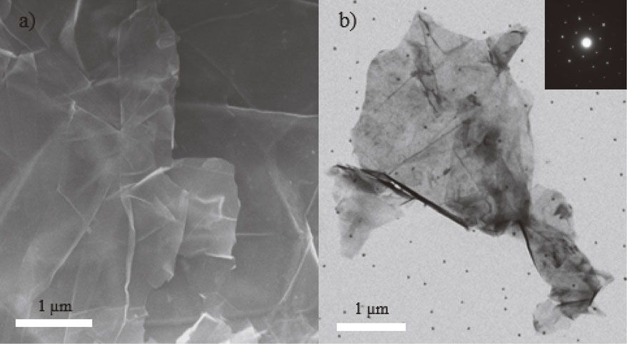
The microstructure and morphology of the GNPs were characterized by using both FE-SEM and TEM. Figure 3(a) and 3(b) show the electron micrographs of the as-synthesized GNPs obtained from condition IV. Some areas of the GNPs surface are quite smooth. There are curls, folds, and wrinkles as well as agglomerations which are inevitable. These exhibit a low number of isolated sheets randomly stacking together. Some parts of the GNPs with a higher number of layers are more clearly visible. Moreover, a selected area electron diffraction (SAED) pattern (the inset of Fig. 3(b)) shows that a hexagonal pattern of diffraction spots could be identified as typical graphene layers. So, the selected area of the GNPs is a single crystal. These results confirm that the graphite sheets are exfoliated into the GNPs.
3.2 Electrical resistivity of ECAA
The electrical resistivity of the ECAA was measured by using the van der Pauw method. The resistivity of the ECAA, containing the obtained GNPs from different conditions of the electrochemical exfoliation process, is illustrated in Table 3. The GNPs contents in the ECAA are controlled at an average of 5 wt%. The lowest resistivity of the ECAA, containing the obtained GNPs from the two-step process; condition IV, occurs at 1.12 Ω·cm.
Table 3 The resistivity of ECAA containing 5 wt% of the obtained GNPs from all conditions.

As illustrated in Table 3, the GNPs obtained from condition IV with the lowest number of layers provided the ECAA with the lowest resistivity. The resistivity of the ECAA, containing the obtained GNPs from condition II, is lower than that of the ECAA, containing the obtained GNPs from condition III. And, the resistivity of the ECAA, containing the obtained GNPs from condition I, is the highest. So, the resistivity of the ECAA would decrease when the GNPs contained in the ECAA have a lower number of layers. We summarized that a lower number of the GNPs layers is beneficial to the electrical resistivity of the ECAA. As condition IV of the electrochemical exfoliation process provided the GNPs with the lowest resistivity of the ECAA, the contents of the obtained GNPs from condition IV would be varied from 1.60 to 6.92 wt% to investigate the percolation threshold.
Then, the different contents of GNPs obtained from the two-step process were blended with the UV-cured acrylate adhesive to fabricate the ECAA. As seen in Fig. 4, the electrical resistivity abruptly decreases by more than 80% as the contents of GNPs increase from 1.60 to 2.10 wt%. The resistivity continues decreasing to 90% when the GNPs contents reach 3.26 wt%. It is due to the tunneling effects of the closed flakes’ GNPs in the ECAA. The percolation threshold is found at 3.26 wt% as the GNPs are already connected and completely formed the electrical network.22,23) The lowest resistivity of the ECAA, containing 6.92 wt% of the obtained GNPs from the two-step process, is at 1.09 Ω·cm.

Finally, two essential factors play an important role in the electrical resistivity of the ECAA. These factors are the electrical properties of the as-synthesized GNPs and the electrical network formation in the ECAA. The former is related to the characteristics of the GNPs. It was shown that a lower number of GNPs layers provided the low resistivity of the ECAA. The latter originates from an aggregation of the GNPs in the ECAA and the preparation process of the ECAA, as well as, depends on polymers used in the matrix.
4. Conclusions
The graphene nanoplatelets (GNPs) were synthesized via the electrochemical exfoliation method. The Raman spectra and XRD results demonstrated that the two-step electrochemical exfoliation process yields the best quality of the as-synthesized GNPs over the other conditions of the one-step process. The ID/IG, I2D/IG, and FWHM(2D) from the Raman spectra also confirmed that the as-synthesized GNPs were multilayer graphene with low defect concentration. Additionally, the XRD pattern of the as-synthesized GNPs, obtained from the two-step process, provided the fewest number of the GNPs layers when compared to the number of the GNPs layers obtained from the other conditions of the one-step electrochemical exfoliation process. The ECAA, which contained 6.92 wt% of the obtained GNPs from the two-step electrochemical exfoliation process, yields the lowest electrical resistivity at 1.09 Ω·cm without any other additional additive. Finally, this research showed an improvement in the ECAA, which contained only the GNPs as fillers to replace soldering lead in the future.
Acknowledgment
The authors would like to thank the Ratchadapisek Research Funds for Graphene Electronics Research Unit and the Interdisciplinary Program in Nanoscience and Technology, Graduate School, Chulalongkorn University.
REFERENCES
- 1) M. Mahurpawar: Int. J. Res. Granthaalayah 3 (9SE) (2015) 1–7. doi:10.29121/granthaalayah.v3.i9SE.2015.3282
- 2) K. Kago, K. Suetsugu, S. Hibino, T. Ikari, A. Furusawa, H. Takano, T. Horiuchi, K. Ishida, T. Sakaguchi, S. Kikuchi and K. Matsushige: Mater. Trans. 45 (2004) 703–709. doi:10.2320/matertrans.45.703
- 3) J.-c. Zhao, J.-d. Hu, D.-n. Jiao and S. Tosto: Trans. Nonferrous Met. Soc. China 24 (2014) 1773–1778. doi:10.1016/S1003-6326(14)63252-0
- 4) G. Johnsen, M. Knaapila, Ø. Martinsen and G. Helgesen: Compos. Sci. Technol. 72 (2012) 1841–1847. doi:10.1016/j.compscitech.2012.07.011
- 5) Y. Guan, X. Chen, F. Li and H. Gao: Int. J. Adhes. Adhes. 30 (2010) 80–88. doi:10.1016/j.ijadhadh.2009.09.003
- 6) I.D. Rosca and S.V. Hoa: Carbon 47 (2009) 1958–1968. doi:10.1016/j.carbon.2009.03.039
- 7) B.M. Amoli, J. Trinidad, G. Rivers, S. Sy, P. Russo, A. Yu, N.Y. Zhou and B. Zhao: Carbon 91 (2015) 188–199. doi:10.1016/j.carbon.2015.04.039
- 8) Q.-P. Feng, J.-P. Yang, S.-Y. Fu and Y.-W. Mai: Carbon 48 (2010) 2057–2062. doi:10.1016/j.carbon.2010.02.016
- 9) B. Chen, J. Tang, G. Zhang, S. Chen and J. Zhang: Mater. Trans. 58 (2017) 842–844. doi:10.2320/matertrans.M2016464
- 10) T.J. Booth, P. Blake, R.R. Nair, D. Jiang, E.W. Hill, U. Bangert, A. Bleloch, M. Gass, K.S. Novoselov, M.I. Katsnelson and A.K. Geim: Nano Lett. 8 (2008) 2442–2446. doi:10.1021/nl801412y
- 11) A.K. Geim and K.S. Novoselov: Nat. Mater. 6 (2007) 183–191. doi:10.1038/nmat1849
- 12) A.A. Balandin, S. Ghosh, W. Bao, I. Calizo, D. Teweldebrhan, F. Miao and C.N. Lau: Nano Lett. 8 (2008) 902–907. doi:10.1021/nl0731872
- 13) Y. Zhang, T.-T. Tang, C. Girit, Z. Hao, M.C. Martin, A. Zettl, M.F. Crommie, Y.R. Shen and F. Wang: Nature 459 (2009) 820–823. doi:10.1038/nature08105
- 14) K.S. Novoselov, A.K. Geim, S.V. Morozov, D. Jiang, Y. Zhang, S.V. Dubonos, I.V. Grigorieva and A.A. Firsov: Science 306 (2004) 666–669. doi:10.1126/science.1102896
- 15) F. Liu, C. Wang, X. Sui, M.A. Riaz, M. Xu, L. Wei and Y. Chen: Carbon Energy 1 (2019) 173–199. doi:10.1002/cey2.14
- 16) X. Huang, S. Li, Z. Qi, W. Zhang, W. Ye and Y. Fang: Nanotechnology 26 (2015) 105602. doi:10.1088/0957-4484/26/10/105602
- 17) H.C. Chiang, C.H. Liu and R.C.C. Tsiang: J. Polym. Sci. A 46 (2008) 8149–8158. doi:10.1002/pola.23112
- 18) O. Philips’Gloeilampenfabrieken: Philips Res. Rep. 13 (1958) 1–9.
- 19) Y. Lan, M. Zondode, H. Deng, J.-A. Yan, M. Ndaw, A. Lisfi, C. Wang and Y.-L. Pan: Cryst. 8 (2018) 375. doi:10.3390/cryst8100375
- 20) A.C. Ferrari, J.C. Meyer, V. Scardaci, C. Casiraghi, M. Lazzeri, F. Mauri, S. Piscanec, D. Jiang, K.S. Novoselov, S. Roth and A.K. Geim: Phys. Rev. Lett. 97 (2006) 187401. doi:10.1103/PhysRevLett.97.187401
- 21) P. Saini, R. Sharma and N. Chadha: Indian J. Pure Appl. Phys. 55 (2017) 625–629.
- 22) R. Aradhana, S. Mohanty and S.K. Nayak: Int. J. Adhes. Adhes. 99 (2020) 102596. doi:10.1016/j.ijadhadh.2020.102596
- 23) W.-J. Jeong, H. Nishikawa, D. Itou and T. Takemoto: Mater. Trans. 46 (2005) 2276–2281. doi:10.2320/matertrans.46.2276

;%0A%09%09%09newWindow.document.open();%0A%09%09%09newWindow.document.write('<img src=%22./Graphics/MT-M2023179tab01.jpg%22>');%0A%09%09%09newWindow.document.close();%0A%09%09)

;%0A%09%09%09newWindow.document.open();%0A%09%09%09newWindow.document.write('<img src=%22./Graphics/MT-M2023179tab02.jpg%22>');%0A%09%09%09newWindow.document.close();%0A%09%09)
;%0A%09%09%09newWindow.document.open();%0A%09%09%09newWindow.document.write('<img src=%22./Graphics/MT-M2023179tab03.jpg%22>');%0A%09%09%09newWindow.document.close();%0A%09%09)