Abstract
A bracket complex is a type of bearing system located on the top of a column and transmits the vertical load of the roof to the column. Bracket complexes are often used in Buddhist temples and Shinto shrines constructed using traditional timber structure. The bracket complex, being a combination of timber blocks and beam like elements, is said to have a positive effect on the seismic performance of traditional timber structures. However, this hypothesis has not been theoretically or quantitatively proven. The aim of the present paper is to clarify the dynamic performance of the bracket complex. The investigations of the present study were performed through experiments and analysis. Shaking table tests were conducted on four different types of bracket complexes. The stiffness, natural frequency, and load-displacement relationships were determined. The results were compared with those obtained by static lateral loading tests on the same specimen by the authors in previous studies. Earthquake response analyses were carried out by applying a structural model proposed by the authors based on the results of static lateral loading tests. The results of the analysis and shaking table tests are compared, and the validity of the proposed structural model is discussed.
Edited by Yositika UTIDA, M.J.A.
1. Introduction
A bracket complex is a type of bearing system, which is usually located on the top of a column, supporting the heavy roof and outstretching eaves and transmitting the vertical load of the roof to the columns. The bracket complex is said to have been first introduced in Japan from China in the 6th century, when Buddhism first reached Japan.1)
The bracket complex is composed of cubic elements (daito and masu) and a beam-like element (hijiki). These elements are combined by timber dowels and halved joints, with no resistance to uplifting force. Therefore, these elements can be dismantled in the course of repair. The bracket complex is said to have a positive effect on the seismic performance of traditional timber structures, but this hypothesis has not been theoretically or quantitatively proven. The present paper attempts to reveal the dynamic characteristics of the bracket complex through the results of shaking table tests.
2. Previous research
The structural characteristics of the bracket complex are often referred to in connection with the seismic performance of traditional timber pagodas in Japan (Fig. 1), reflecting the fact that there are no documents indicating the collapse of a large-scale timber pagoda due to an earthquake in Japan. Many discussions have been done on the seismic performance of timber pagodas, and the positive effect of the bracket complex has been pointed out by prominent researchers.2),3) Research on the structural performance of the bracket complex has been performed by Ban,4) Nishizawa,5) Yamada,6) Hayashi/Karube,7),8) Kusunoki,9) and others. Based on these previous studies, several common characteristics of the bracket complex, such as the load displacement hysteresis curve showing a spindle shape and the horizontal stiffness being influenced by the vertical load, can be pointed out. Because of the large variation in the combination and details of the bracket complex, the structural characteristics and performance of the bracket complex has not been thoroughly clarified.

The authors have performed static and dynamic loading tests on four fundamental types of bracket complexes, the outline of which was introduced in a conference proceeding paper.10) Based on the results of the static loading tests, a hysteresis model was developed and stiffness evaluation was performed by the authors and reported.11) Additional static loading tests were performed in order to clarify the behavior in the large displacement range and reported in a conference proceeding paper.12) The present paper attempts to reveal the results of shaking table tests in comparison with the two above mentioned static loading tests. Therefore, an outline and the results of the static loading tests (Fig. 2) as well as the proposed hysteresis model are explained briefly hereinafter. The specimen and testing conditions (denoted as the phase) are explained in Section 3.

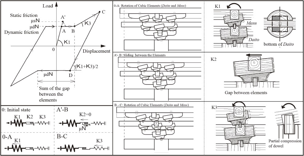
The load displacement relationship of each specimen determined by the static loading test is shown in Fig. 3. Although the shape and combination of brackets are different and complex, we showed that the results can be idealized by a multi-linear model, as shown in Fig. 4. The fundamental deformation characteristics at each stage of deformation are also shown in Fig. 4 (reproduced from Reference 11).
For each procedural step of the multi-linear model, the stiffness is determined theoretically based on the deformation observed in the experiment as follows (details of the stiffness evaluation and calculation are shown in Reference 11).
Initial stiffness: (O-A) Rotation of daito and masu (cubic elements). Stiffness can be determined by the elastic deformation of wood perpendicular to the grain13) at the bottom of daito and masu. This stiffness can be determined from the size and shape of the daito and masu elements and the stiffness of the material.
Second stiffness: (A-B) Sliding between elements. The stiffness is 0, and the resistance is the friction between the timber elements. The friction coefficient between two timber elements was 0.3–0.5 based on experimental results. The length of the sliding is the gap between the elements and therefore depends on the accuracy of construction (approximately 5 mm based on experimental results).
K2 = 0, F2 = µN where µ: 0.3–0.5, N: vertical load (2 tons)
Third stiffness: (B-C) Rotation of daito and masu. When the horizontal sliding displacement exceeds the gap between the elements, the edge of the dowels meets the edge of the holes, and thus daito and masu rotate, and the dowels start to deform. The stiffness at this stage is determined by the stiffness of the elastic deformation of the timber perpendicular to the grain of the dowels.
3. Experimental method
3.1. Specimens.
The four most fundamental types of bracket complexes were selected as test specimens (Fig. 5): Specimen K1; Daito-Hijiki, Specimen K2; Hira-Mitsuto, Specimen K3; De-Mitsuto, Specimen K4; De-Gumi. In the tests, the columns were cut short (to a length of 70 cm) and fastened to the shaking table under the assumption that the rocking angle of the column can be ignored. Four columns were placed at the corners of a square plan of dimensions 2 m by 2 m (Fig. 6), and the bracket complexes were placed on the columns. The bracket complex is a combination of two types of elements called daito and masu (cubic elements) and hijiki (beam-like element). These two elements were placed on top of each other and were connected with wooden dowels and halved joints, as shown in Fig. 7. Specimen K3 is a full-scale model of the bracket complex of an existing Buddhist temple, Kita-in Jigen-do, Important Cultural Property. The other specimens were designed based on Specimen K3.
3.2. Testing method.
A shaking table with three-dimensional movement of the Technical Institute of Tokyu Construction Company was used in the experiment. The response acceleration, velocity, and displacement were measured using accelerograms and displacement transducers. The movements of the specimens were recorded using nine video tape recorders. The tests were carried out under four conditions: a combination of two different vertical loads and two different conditions of the specimen (with or without a biwa-ita, i.e., a timber board), as shown in Fig. 8. These four conditions were denoted as Phases A, B, C, and D. The two different vertical loads correspond to different types of roofing. The vertical stress was calculated for columns of several buildings with different types of roofing, and the average stress value was obtained. The two conditions of vertical load adopted for the experiment were 1) 2 tons (0.5 tons/column), representing thatched cypress bark roofs, and 2) 12 tons (3 tons/column), representing clay tile roofs. The biwa-ita is a board that is installed between the beam and the column. The biwa-ita is approximately 15-mm thick and is placed inside a 10-mm deep groove cut in the attaching element (Fig. 7).

The schedule of the shaking table excitation is shown in Table 1. The excitations were predominantly one-dimensional horizontal excitations. However, since sliding and rocking were assumed to be two major vibration modes, two-, and three-dimensional excitations (horizontal and vertical) were also conducted for comparison.
Table 1. Schedule of excitation
| Input Motion |
Dimension |
Level |
| Micro Tremour |
3D-XYZ |
— |
| Random Noise |
1D-X |
20 Gal |
50 Gal |
— |
| 1D-Z |
20 Gal |
50 Gal |
— |
| 1D-Y |
10 Gal |
20 Gal |
— |
| Sine Sweep |
1D-X |
20 Gal |
50 Gal |
— |
| 1D-Z |
20 Gal |
50 Gal |
— |
| 1D-Y |
10 Gal |
20 Gal |
— |
| JMA Kobe |
1D-X |
10 kine |
25 kine |
50 kine |
| 2D-XZ |
X:10 kine |
X:25 kine |
X:50 kine |
| 3D-XYZ |
X:10 kine |
X:25 kine |
— |
| Sine Wave |
1D-X |
(2 Hz) 0 → 200 Gal |
| 2D-XZ |
X:(2 Hz) 0 → 200 Gal Z:(7 Hz) 50 Gal |
The values of the input motions shown in Table 1 are as follows.
Random noise: A band-limited white noise excitation: X; 0–30 Hz, Y, Z; 0–50 Hz.
Sine sweep: Sine wave excitation with a constant amplitude of acceleration, and a frequency that increases by 0.25 Hz at each step. The duration of each step was five seconds.
JMA Kobe: The acceleration record measured at the Kobe Meteorological Station during the 1995 Hyogoken-Nanbu Earthquake was used as the principle input motion. The acceleration records of the NS and EW directions were used for the X and Y directions, respectively. The maximum input acceleration of the NS direction was normalized to 10, 25, and 50 kine.
Sine wave: Sine wave excitation with a constant frequency and an acceleration that is varied from 0 to 200 Gal. The duration of the excitation was two minutes.
4. Results of the shaking table test
4.1. Results of random noise excitation.
An example of the results of the fundamental vibration characteristics of the specimens by random noise excitation (maximum acceleration: 50 Gal) is shown in Table 2. The damping ratio was calculated from the acceleration response, and the dynamic equivalent stiffness was calculated from the natural frequency and the mass of the specimens. The maximum relative displacement measured in the excitation was approximately 1/3,000 rad, which is well within the initial stiffness range. The damping ratio was 4%–9%, and the natural frequency was 5–18 Hz. Comparison of the results for Phase B with those of Phase C shows that when the timber board (biwa-ita) is installed, the stiffness has a tendency to increase by approximately 1.35–1.9 times. By comparing the results for Phase A with those of Phase B, the stiffness of the brackets has a tendency to increase 1.5 times as the vertical load increases.
Table 2. Results of the shaking table test (random noise 50 Gal excitation)
| Specimen (Height*) |
Phase |
Biwa Ita |
Vertical Load |
Damping Ratio |
Natural Frequency |
Equivalent Stiffness |
| cm |
ton |
% |
Hz |
kN/cm |
kN/rad |
| K1 |
A |
○ |
2 |
4.6 |
18.0 |
256 |
5116 |
| 20.0 |
B |
○ |
12 |
8.1 |
9.0 |
384 |
7675 |
| C |
— |
12 |
7.8 |
7.8 |
285 |
5691 |
| K2 |
A |
○ |
2 |
4.4 |
15.3 |
185 |
6765 |
| 36.6 |
B |
○ |
12 |
8.0 |
7.8 |
285 |
10414 |
| C |
— |
12 |
6.5 |
6.6 |
208 |
7610 |
| K3 |
A |
○ |
2 |
6.4 |
15.4 |
187 |
6853 |
| 36.6 |
B |
○ |
12 |
9.4 |
7.5 |
266 |
9753 |
| C |
— |
12 |
6.5 |
5.6 |
150 |
5486 |
| K4 |
B |
○ |
12 |
8.5 |
8.0 |
303 |
16858 |
| 55.6 |
C |
— |
12 |
6.8 |
5.8 |
159 |
8861 |
Height*: Top of column to bottom of timber beam
The natural frequencies of all of the measured excitations are shown in Fig. 9. The natural frequency of vibration ranges from 13 to 20 Hz for Phase A (0.5 tons/column) and from 5 to 10 Hz for Phases B and C (3 tons/column). The natural frequency has a tendency to decline as the components of the bracket complex increase. The natural frequency also decreases as the input acceleration increases due to the nonlinearity of the timber structures.
4.3. Equivalent stiffness.
The equivalent stiffness normalized by the height of the specimen for all excitations are shown in Fig. 10. The average proportion of the equivalent stiffness of Phase B divided by that of Phase C is 1.43, which indicates the effect of the confinement of the timber board. In the actual situation, the board cannot be expected to be as precisely installed as that of the specimen. Therefore, this value represents the maximum effect of the board on the stiffness of the bracket complex.

The average proportion of the equivalent stiffness of Phase B divided by that of Phase A is 1.22, which indicates the effect of the increase in the vertical load from Phase A (0.5 tons/column) to Phase B (3 tons/column). This is a result of the fact that the centers of rotation of the cubic elements (daito and masu) are not fixed. Therefore, as the vertical load increases, the uplifting of the elements is confined and the center of rotation shifts so that the diameter of the compressive deformation by rotation increases. Since the theoretical stiffness of the elastic deformation of timber perpendicular to the grain is proportional to the rotation diameter of elastic deformation, the increase in stiffness can be theoretically proven.
The stiffnesses as determined by horizontal static loading tests and theoretical calculations are shown in Fig. 11 for comparison. The stiffness was determined by the tangent stiffness of the load displacement relationship, as determined by the static loading test. The theoretical initial stiffness was determined under the assumption of either rotation mode deformation or shear mode deformation, as shown in Fig. 12. (1) Rotation mode: the bracket rotates as one body, and only the bottom of the daito exhibits compressive deformation. (2) Shear mode: the beams and beam-like elements shift horizontally, and all of the cubic elements (daito and masu) rotate so that the bracket acts as a single shearing body. The stiffness is realized by the compressive deformation of all the cubic elements. Based on the static experiment, the results obtained under the shear mode assumption showed good agreement with the results of the static experiment, whereas the results of the shaking table test agreed with the results obtained under the rotation mode assumption. However, a closer look revealed that the results of the shaking table tests for the smaller amplitude showed prominent agreement with the results obtained under the rotation mode, and as the amplitude became larger, the results of the shaking table tests agreed with those obtained under the shear mode assumption. The results of the static loading tests for Specimen K2, which were performed in the minor displacement range (Fig. 3), show the characteristics of the rotation mode. In the experiment, the top of the specimen was confined by steel beams so that the bracket complex would behave as a shearing body. Therefore, only a small change in amplitude was observed under the assumption of the rotation mode. In actual existing structures, the deformation mode of the bracket complex is dependent on the rigidities of the beam and the roof truss, which are supported by the bracket complex.

The equivalent shear force (response acceleration multiplied by mass) and displacement relation obtained by the sine sweep excitation of Specimen K4 Phase C is shown in Fig. 13 as an example. The relations show high energy dissipation, and as the response reaches resonance frequency, the viscous damping ratio reaches 0.9. As shown in Fig. 14, the viscous damping ratio is dependent on the input frequency.
4.5. Load displacement relation.
The load displacement relations of Specimen K4 Phase C as determined by shaking table test and static loading test are shown in Fig. 15. The equivalent shear force was determined by multiplying the mass and the response acceleration by shaking table test. The input motion of the shaking table test was the acceleration record of the 1995 Kobe earthquake NS direction (JMA Kobe). The maximum velocity was normalized to 50 kine. The results are shown by the red line. In order to compare the dynamic effect, the load displacement relations by the static loading test for Phases C and D are illustrated in the same graph by the green line and the blue line, respectively. The difference in the two phases is the vertical load, where Phase C carries a vertical load of 12 tons (3 tons/column) and Phase D carries a vertical load of 2 tons (0.5 tons/column). The results for Phase C show that the overall hysteresis relation is constant between the dynamic test and the static test. The initial stiffness corresponds well with the results of the static test, and the second stiffness appears at approximately 40 kN. Based on the static test, the second stiffness deformation mode is slipping between the elements. Since the vertical force is 118 kN (3 tons/column) the friction coefficient can be determined as 0.34. The dynamic hysteresis relation is fairly smooth in the second stiffness range, where the results of the static test have a jagged shape, indicating the stick-slip phenomenon by static and dynamic (kinetic) friction. The results of the static loading test for Phase D show that the initial stiffness is much lower as compared to Phase C for both the dynamic test and the static test. As explained earlier, the initial stiffness is the result of the partial compression of timber perpendicular to the grain by rotation of the daito (cubic element). Therefore, the stiffness is sensitive to the vertical load it carries. Based on the results of the dynamic tests, the average stiffness increase was 1.22 for an increase in weight of six times (2–12 tons).

Figure 16 shows the same load displacement relationship as Fig. 15, but the vertical axis is normalized (divided) by the vertical load in order to compare the two different phases. The results show that the overall hysteresis curvature corresponds fairly well for both the static and dynamic tests and that the slipping occurs at a base shear coefficient (friction coefficient) of 0.4.

Figure 17 shows the load displacement relation and the deformation of each element measured at maximum horizontal displacement of the top beam (magnification factor indicated in the illustration) for all specimens. In order to compare the results of the static loading test, which were obtained primarily for Phase D, and the results of the shaking table test, which was performed for Phase C, the shear force was normalized by the vertical load as the base shear coefficient. The horizontal axis was normalized by the height of the specimen in order to compare the different specimens. The initial stiffness shows a lower value for the shaking table test, which is not a dynamic effect but rather the effect of the difference in the vertical load. The sliding of the elements or the second stiffness range appears at around 0.3 for the shaking table test and at 0.4–0.5 for the static loading test, which correspond to the dynamic and static friction coefficients. The third stiffness is only apparent for Specimen K4. For Specimens K3 and K4, the results of the shaking table tests show that the second stiffness tends to increase from zero at approximately 0.01 rad., indicating that the rotation of the cubic elements and the compressive deformation of the dowels occur continuously with the slipping of the elements. For Specimens K1 and K2, because there are no orthogonal beam elements, it is understandable that the third stiffness does not appear. Although the four bracket complexes used in the experiment appear to have a complex structure, including many elements combined by dowels and halved joints, the load displacement relation and corresponding deformation behavior can be explained by a single structural model proposed based on the static lateral loading test.

5. Earthquake response analysis.
Non-linear earthquake response analysis of the bracket complexes was carried out using the proposed structural model (Fig. 4). The specimen was idealized by a single-mass shearing body, and the Newmark β method was used. Figures 18 and 19 show the results for Specimens K3 and K4. In the figures, the results for the load displacement relation, time history of relative displacement, and time history of the equivalent shear force obtained by the response analysis and shaking table tests are shown for comparison. The input motion for both the response analysis and the shaking table tests was the acceleration record of JMA Kobe NS, with a maximum velocity of 50 kine. The results of the analysis show reasonably good agreement with the results of the shaking table test until 19 s for Specimen K3 and until 17 s for Specimen K4. When the relative displacement exceeds −1 cm in the shaking table test, the values of relative displacement from the analysis become smaller than the values obtained from the shaking table test. This is because the movement of the bracket complex is dependent on the frictional capacity of the specimen, and the relative displacement greatly increases once the shear force reaches the value of frictional capacity. Thus, the amplitude of the shear force does not differ greatly. Although the parameters used in the model require further consideration, the proposed model is shown to be appropriate for idealizing the bracket complex.

6. Discussion
6.1. Structural characteristics of the bracket complex.
Based on the results of the shaking table tests, the bracket complex used in Japanese traditional timber structures exhibited high energy dissipation. In the small-amplitude range, the viscous damping caused by the elastic deformation of timber perpendicular to the grain resulting from the rotation of the cubic elements (daito and masu) can be assumed. When the horizontal force exceeds the frictional capacity, slipping between timber elements occurs, which causes large Coulomb damping. After the slipping between the elements absorbed the sum of the gap between the elements, compression of the dowels and halved joints showed that the elastic deformation of timber perpendicular to the grain occurred. The characteristics of the system are such that because the deformation is accompanied by slipping, no stiffness degradation is observed from multiple cycles, even for a deformation of 1/30 rad. The reason for this is that the displacement is distributed among multiple timber elements, each of which is still within the elastic range.
6.2. Effect of the bracket complex on the overall structure.
Two examples of traditional timber structures of Buddhist temples are shown in Figs. 20 and 21. Figure 20 depicts the section of a hall (Jigen-do) in Kita-in temple. This building was selected as the model of the specimens. Figure 21 depicts the section of a hall (Bustu-den) in Kencho-ji temple. Both the buildings are designated as Important Cultural Properties by the Japanese national government. As seen from the sections, the bracket complex is set on top of the column or frame supporting the heavy load of the roof and outstretching eaves. In the course of a seismic event the bracket complex transmits the inertia force between the roof system and the frame. The bracket complex is in serial connection with the roof and frame (Note 2). Therefore, the relative proportion of the rigidity of the frame and bracket complex will define the performance of the overall structure. If the rigidity of the bracket complex and that of the frame are similar, the bracket complex can be expected to respond and dissipate the vibrational energy from seismic motion. The rigidity of the bracket complex, as determined from experiments, decreases according to the increase in the stacked elements. For a fairly simple bracket complex, as in the case of Kita-in (Fig. 20), the rigidity of the bracket complex is approximately ten times that of the frame.14) Whereas the example of Kencho-ji (Fig. 21), with multiple layers of elements, the rigidity of the bracket complex and that of the frame are approximately the same14) and can be expected to respond in the course of a seismic event and contribute as an energy dissipation device on the overall structure.

7. Conclusion
In order to clarify the dynamic performance of the bracket complex, shaking table tests were performed on full-scale models of four fundamental types of bracket complexes used in traditional timber architecture in Japan. The natural frequencies of vibration, damping factor, equivalent stiffness, and equivalent load displacement relationships were determined. Two types of vertical load, corresponding to a thatched roof (0.5 tons/column) and a clay tile roof (3 tons/column), were tested in order to determine the effect of a vertical load.
The natural frequency of vibration in the first mode was 4–10 Hz for the clay tile roof specimens. The equivalent initial stiffness as determined from the mass and measured natural frequency of vibration exhibited a tendency to decline as the brackets became more complex and as the number of components increased. The equivalent stiffness increased by 1.43 times on average when the timber board (biwa-ita) was installed due to the confinement by the board. However, in actual constructions, the board cannot be expected to be installed as precisely as in the experimental specimen. Therefore, the confinement and increase in equivalent stiffness as determined by the experiment are the maximum expected values. As a result of the increase in the vertical load, the equivalent stiffness increased by 1.22 times on average from the thatched roof (0.5 tons/column) to the clay tile roof (3 tons/column). The initial stiffness was realized by the compression of timber from the rotation of the cubic element (daito and masu). Moreover, since the center of rotation is not completely fixed (only by timber dowels), the increase in the vertical load confined the uplifting of the cubic element. Since the compressive stiffness is proportional to the rotation diameter, the increase in vertical load increased the initial stiffness. The load displacement relation by sine sweep excitation showed high energy dissipation and a large viscous damping ratio ranging from 0.2 to 0.9, which was dependent on the frequency. The viscous characteristic of the compressive strain of timber perpendicular to the grain, especially in the small-deflection range, requires further study.
The results of shaking table tests were compared with those of previously conducted static horizontal loading tests on the same specimens. From the load displacement hysteresis curve and deformation characteristics, in the initial stiffness range, the rotation of cubic elements (daito and masu) was clarified to be the dominant deformation. The second stiffness was approximately zero, as realized by the slippage between the elements with a friction coefficient ranging from 0.3 to 0.5, and the third stiffness was continuous over the second stiffness range, but rotation of the cubic elements was observed. The overall hysteresis and deformation characteristic were observed to be constant with respect to those determined by the static loading tests. The results of the shaking table tests were compared with those of the non-linear earthquake response analysis. The analysis was carried out using the proposed structural model based on the static lateral loading test by the authors in a previous study. It was proven that, although the parameters require further consideration, the model is applicable to and appropriate for idealizing the bracket complex used in traditional timber structures.
In the course of a seismic event, the bracket complex transmits the shear force between the roof system and the frame. Since the bracket complex is in serial connection with the frame, the relative proportion of the rigidity of the frame and bracket complex will define the performance of the overall structure. If the rigidity of the bracket complex and that of the frame are similar, the bracket complex can be expected to respond and contribute as an energy dissipation device on the overall structure.
Note
(Note 1) The elastic deformation of timber perpendicular to the grain was determined by the following equation:13)
| \begin{equation*}
\text{M} = \frac{x_{p}^{3}y_{p}C_{y}E_{\bot}\theta}{z_{0}}\left(C_{xd} + \frac{1}{3} \right),
\end{equation*}
|
where
-
M: moment,
-
θ: rotation angle,
-
E⊥: Young’s modulus, compression perpendicular to the grain,
| \begin{equation*}
C_{y} = 1 + \cfrac{\varPhi\biggl( \cfrac{2ny_{1}}{z_{0}}\biggr) + \varPhi \biggl( \cfrac{2ny_{2}}{z_{0}} \biggr) - 1}{\cfrac{0.8ny_{p}}{z_{0}}},
\end{equation*}
|
| \begin{equation*}
C_{xd} = \cfrac{\varPhi \biggl( \cfrac{2x_{1}}{z_{0}} \biggr) - \cfrac{1}{2}}{\cfrac{0.8x_{p}}{z_{0}}},
\end{equation*}
|
| \begin{equation*}
\varPhi (X) = \int_{-\infty}^{X}\frac{1}{\sqrt{2\pi}}e^{-\frac{X^{2}}{2}}dX,
\end{equation*}
|
-
n: coefficient factor depending on the status of the grain (n = 5–7).
(Note 2) The rigidity of the roof system is normally much larger compared with that of the frame, resulting from the confinement of the thick thatch or clay tile roofing. This can be proven based on the damage to traditional timber structures caused by earthquakes. Specifically, although the frame is crushed, the roof remains as an intact body.
Acknowledgements
The experiments of the present paper were conducted as part of a cooperative research project by the Tokyu Construction Company, the Japanese Association for Conservation of Architectural Monuments, and Sakamoto Laboratory, the University of Tokyo, and were funded by the Agency of Cultural Affairs of the national government of Japan. The author would like to express her sincere gratitude to Professor Isao Sakamoto, Professor Emeritus of the University of Tokyo, Professor Yoshimitsu Ohashi of Tokyo City University, Dr. Masahiko Kimura of the Tokyu Construction Company, Mr. Kazuo Yasuda of JACAM (The Japanese Association for Conservation of Architectural Monuments), Mr. Yoshikazu Mizunuma of the Shimizu Company, and all of the former members of Sakamoto Laboratory of the University of Tokyo and Fujita Laboratory of Tokyo Metropolitan University. I would like to express gratitude to Kencho-ji and Kita-in for their permission to use pictures and drawings of the temple. My deepest appreciation to Professor Shuichi Matsumura of the University of Tokyo for all his support and encouragement.
References
- 1) Fujii, K. (1994) Rhetoric in Japanese Architecture–Observing Bracket Complexes (INAX ALBUM 21). INAX Publishing, Tokyo (in Japanese).
- 2) Tanabashi, R. (1960) Earthquake resistance of traditional Japanese wooden structures. In Proc. of the Second World Conference on Earthquake Engineering Japan, Vol. 1 (Tokyo and Kyoto, 1960). Science Council of Japan, Tokyo, pp. 151–163.
- 3) Yamabe, K. and Kanai, K. (1988) Study on the aseismic properties of the Gozyunotos (Pagodas). J. Coll. Ind. Tech., Nihon Univ. 21, 91–110 (in Japanese).
- 4) Ban, S. (1944) Research on the Stability of Buddhist Hall Structures, No. 8 Structural Properties of Buddhist Temple Structures No. 4. Conservation and Restoration Division of Agency for Cultural Affairs, Tokyo (in Japanese).
- 5) Nishizawa, H. (1996) Basic Research on the Seismic Properties of Traditional Timber Structures, Structural Properties of Bracket Complexes and Hanging Walls. Department of Architecture, Kyoto University (in Japanese).
- 6) Yamada, N. (1997) Dynamic Response Analysis of Three Dimensional Frame Structures Subjected to Two Dimensional Earthquake Strong Motion, Earthquake Response Analysis of Traditional Timber Structures. Graduation Thesis of Department of Architecture, Kyoto University (in Japanese).
- 7) Hayashi, T., Karube, M., Harada, M., Takahashi, T. and Kimura, T. (1998) Full-size test of ancient traditional wooden frame under horizontal loading. Part 1: Outline of the experiment and full-size test of Masu-Gumi structural component. Summ. Tech. Pap. Ann. Meet. Architect. Inst. Jpn. C-1, 267–268 (in Japanese).
- 8) Hayashi, T., Karube, M., Harada, M., Takahashi, T. and Kimura, T. (1998) Full-size test of ancient traditional wooden frame under horizontal loading. Part 2: Full-size test of ancient wooden frame. Summ. Tech. Pap. Ann. Meet. Architect. Inst. Jpn. C-1, 269–270 (in Japanese).
- 9) Kusunoki, T., Nagase, T., Kibayashi, M., Kibayashi, M., Hayashi, Y. and Ueda, T. (2005) Experimental study on the structural behavior of traditional architectural component “Masugumi”. J. Struct. Constr. Eng., AIJ 70 (592), 129–136 (in Japanese).
- 10) Fujita, K., Sakamoto, I., Ohashi, Y. and Kimura, M. (2000) Static and dynamic loading tests of bracket complexes used in traditional timber structures in Japan. In 12th World Conference on Earthquake Engineering. New Zealand Society for Earthquake Engineering, Auckland, Article No. 0851.
- 11) Fujita, K., Kimura, M., Ohashi, Y. and Sakamoto, I. (2001) Hysteresis model and stiffness evaluation of bracket complexes used in traditional timber structures based on static lateral loading tests. J. Struct. Constr. Eng., AIJ 66 (543), 121–127 (in Japanese).
- 12) Mizunuma, Y., Fujita, K. and Sakamoto, I. (2002) Static lateral loading tests of bracket complexes used in traditional timber structures, stiffness evaluation of DEMITSUTO and DAITOHIJIKI bracket complexes. Summ. Tech. Pap. Ann. Meet. Architect. Inst. Jpn. C-1, 265–266 (in Japanese).
- 13) Inayama, M. (1991) Theory and Application of Deformation of Timber Perpendicular to the Grain. Doctoral Thesis, The University of Tokyo (in Japanese).
- 14) Fujita, K. (2018) Mechanics of kumimono. In History, Style, and Society of Architecture (ed. Committee of Thesis Series in Dedication to Professor Keisuke Fujii.). Chuo Kouron Bijyutsu Syuppan, Tokyo, pp. 279–288 (in Japanese).
- 15) Kitain (1976) Repair report of Sanmon, Syourou-mon, Jigen-do, Kuri, Syoin, and Kyakuden of Kita-in temple, Important cultural property (in Japanese).
- 16) Committee for Protection of Cultural Properties (1967) Measurement Survey Report of National Treasures and Important Cultural Properties (Architecture) Vol. 3 (Tokyo and Kanagawa). pp. 8–25 (in Japanese).