Abstract
Toll-like receptors (TLRs) play central roles in innate immune defense against infection by binding to microbial molecules. TLR7 and TLR8 are highly homologous sensors with an RNA ligand preference for single-stranded RNA (ssRNA). Recent works reveal that these TLR sense degradation products of RNA at two distinct binding sites, designated 1st site and 2nd site, rather than long ssRNA. The highly conserved 1st site is responsible for the binding of nucleosides and the 2nd site confers the oligonucleotide binding. Binding of the oligonucleotide at the 2nd site synergistically enhances the affinity for nucleoside to the 1st site. However, it remains unclear why these ligands synergistically activate TLR7 and TLR8. Here, we performed a molecular dynamics (MD) calculation and successive decomposition analysis to clarify what this synergistic effect is derived from. We demonstrated that the main factor of the synergistic effect during the TLR7 and TLR8 activation processes was the lowering of the LRR dimerization barrier, mainly achieved by the reduction of the electrostatic repulsion with the oligonucleotide binding at the 2nd site.
Introduction
Toll-like receptors (TLRs) are a family of innate immune receptors whose activation is crucial for the induction of innate and adaptive immune responses.1) TLRs are type I transmembrane proteins that have been structurally characterized to possess extracellular leucine-rich repeat (LRR) domain, a single transmembrane domain, and a cytoplasmic Toll/interleukin-1 receptor (TIR) domain.2,3) By recognizing pathogen-associated molecular patterns (PAMPs) via the LRR domain, inactive monomeric or preformed dimeric TLRs are induced to form a face-to-face activated dimer.4) Then, TIR domains are brought in proximity and recruit downstream adaptor proteins to initiate transcriptional responses, which finally induce immune responses.5,6)
There are ten TLRs (TLR1–10) in human and nearly half of TLRs (TLR3, TLR7, TLR8, and TLR9) recognize nucleic acid ligands. They reside in endolysosome and respond to double-stranded [ds] RNA (TLR3),7) single stranded [ss] RNA (TLR7 and 8),8,9) and unmethylated CpG containing ssDNA (TLR9).10) TLR7, TLR8 and TLR9 are homologous and constitute TLR7 subfamily. They are the largest TLR proteins containing 26 LRRs and a long inserted loop between LRR14 and LRR15.11–14) This long loop, termed “Z-loop,” plays important roles in receptor function and ligand recognition. TLR7 subfamily is assumed to exist as an inactive preformed dimer prior to ligand recognition, and structural rearrangement is necessary for receptor activation.15) In fact, the apo form LRR domain of TLR8 forms a preformed dimer and the rearrangement occurs to form an active dimer upon ligand binding.13) This preformed dimer contrasts with the ligand-induced dimerization mechanism of other TLRs.
Crystallographic studies of TLR7 and TLR8 have revealed the ligand recognition and activation mechanisms of these receptors.11–13) TLR7 and TLR8 are ssRNA sensors, but small antiviral compounds, e.g., imidazoquinoline derivatives (R848 and imiquimod) and guanine nucleoside analogues (loxoribine, etc.) were initially described for the TLR7 and/or TLR8 agonistic ligands.16–19) Of great interest, structural studies revealed that TLR7 and TLR8 recognize degradation products of RNA at two distinct binding sites, one for nucleosides and small antiviral compounds (1st site), and the other for oligoribonucleotides (2nd site).11,12,20) The 1st site is highly conserved between these TLRs and this site lies within the dimerization interface of these TLRs, and agonistic ligands within this site bridge the two TLR molecules. In contrast, the 2nd site is spatially and structurally distinct (Fig. 1). In both TLR7 and TLR8, the binding affinity of 1st for nucleoside is very weak, but this low-affinity interaction is greatly improved by the presence of ssRNA bound to the 2nd site. However, it remains largely unknown why these ligands synergistically activate TLR7 and TLR8, and what interaction energy causes this synergistic effect. Here, we performed molecular dynamics (MD)-calculation of these systems and report the underlying reason and mechanism of synergistic effect in TLR7 and TLR8.
Results
TLR Activation Model Assumed in This Computational AnalysisThe structural study reveals that TLR8 and TLR7 are in different states of association in the absence of the ligands: TLR8 exists as a preformed dimer and TLR7 exists as a monomer. Upon ligand binding at the 1st site, TLR8 and TLR7 form the active LRR dimer, of which structures are very similar (Figs. 1, 2). Therefore, the activation processes of TLR8 and TLR7 from the different inactive states to a similar active state can be understood in a unified manner by considering the following activation process model under the assumption that a formation of the active LRR dimer occurred first, followed by binding of the nucleoside at the 1st site (Fig. 2), because the binding affinity of the oligonucleotide at the 2nd site is stronger than that of the nucleoside at 1st site in both TLR8 and TLR7.11,12) Hypothetically, the process of the LRR dimer rearrangement from the inactive to active forms was introduced in the case of TLR8 (Fig. 2A), and the LRR dimerization process from the monomer of LRR to the LRR dimer active form was introduced in the case of TLR7 (Fig. 2B). The virtual structures assumed in the LRR rearrangement process and the LRR dimerization process were modeled using MD simulations, and we evaluated them energetically using snapshots sampled by MD simulations. The synergy effect was represented as the difference between the activation processes when oligonucleotide was bound to the 2nd site and when the oligonucleotide was not bound.
Hereafter, the system for TLR8 or TLR7 bound with nucleoside at the 1st site and oligonucleotide at the 2nd site was represented as TLR7 or TLR8/1st site/2nd site.
Synergistic Effect of TLR8 Prompted by the Reduction of the Electrostatic RepulsionThe 1st site of TLR8 is formed by LRR11–14 and LRR16*–18*, and accommodates uridine as well as synthetic ligands such as imidazoquinolines and nucleoside analogs.13) The 2nd site of TLR8 is composed of the concave surface of LRR9–13 and a portion of the Z-loop and accommodates oligonucleotide (Fig. 1). Throughout this paper, we indicate the second TLR in the dimer with asterisks. In TLR8, the binding affinity of the 1st site for uridine is very weak with a Kd value of 55 µM. However, the affinity of TLR8 to uridine is significantly increased to 1 µM in the presence of ssRNA.12)
We performed MD simulations of LRR dimer of TLR8 with bound uridine (URI) and 20-mer agonist ssRNA (ORN06) in solution (Fig. 3A), and solution structures were sampled. During 1 µs MD simulation, each LRR domain itself in the LRR dimer maintained its structure: Root mean square deviations of Cα atoms (Cα-RMSD) for TLR8/URI/ORN06 were about 2–3 Å (Fig. 3B). Their relative positions changed up to approx. 5–8 Å of Cα-RMSD (Fig. 3B), but not enough to cause the dimer to collapse.
The energy of the activation process was lower when ORN06 was present at the 2nd site: the activation energy was approx. −1339 kJ/mol when ORN06 was unbound, whereas it changed to approx. −2390 kJ/mol when ORN06 was present (Fig. 4), where the activation energy was calculated from the difference of the MM-PB/SA energy of TLR8/ / and TLR8/URI/ /, and TLR8/ /ORN06 and TLR8/URI/ORN06. It suggested that the LRR rearrangement was promoted by the ORN06 binding at the 2nd site, and that the driver for the synergy effect of TLR8 was the promotion of the LRR rearrangement. According to the energy decomposition analysis, the electrostatic energy was found to be the main factor of the reduction of the rearrangement energy (Fig. 4); Most of the electrostatic energy was canceled by the polar solvation energy, but in the TLR/URI/ORN06 system, the change in the electrostatic energy from that of TLR8/URI/ / system was not able to be canceled by polar solvation energy because of the decrease in the polar solvation energy, and the contribution in the change between the electrostatic energy and the polar solvation energy was larger than that of the change between the van der Waals energy and solvent accessible surface area (SASA) energy.
In addition, to understand the energetical and structural contribution at the residue level, we specified the energetically affected residues from ORN06 by the energy decomposition analysis. The top 10 residues with larger negative change of interaction energy upon ORN06 binding (Fig. 5A). The top 10 residues were located at the interface of the dimer (Fig. 5B). The interaction with ORN06 shifted the basic residues into closer proximity. This was unlikely in the absence of ORN06. For example, R375 and R569 located at the interface were shifted into closer proximity upon ORN06 binding (Fig. 5C). Although this was a local change at the sidechain level, it might be a part of the structural change brought by the presence of ORN06.
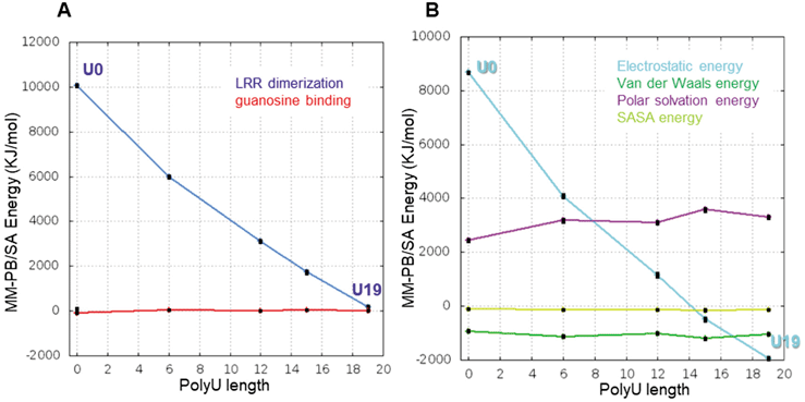
Synergistic Effect of TLR7 in a PolyU Length MannerThe 1st site of TLR7 is essentially the same as that of TLR8, formed by LRR11–14, and LRR16*–18* and accommodates guanosine and the synthetic ligands.11,21,22) The 2nd site of TLR7 is composed of the concave surface of LRR1–5 and a portion of the Z-loop, and this site is spatially and structurally distinct of that of TLR8 (Fig. 1). TLR7 prefers ssRNA containing two consecutive uridine nucleotides at the 2nd site. TLR7 exhibits the binding affinity of the 1st site for guanosine with a Kd value of 13.5 µM. The affinities of guanosine for TLR7 were markedly enhanced to Kd = 0.93 µM in the presence of polyU_19mer. Of note for TLR7, the binding capacity of guanosine increased as the polyU at the 2nd site became longer: polyU_12mer, polyU_9mer, and polyU_6mer enhanced the affinity for guanosine, yielding Kd values of 1.2, 1.6, and 1.5 µM, respectively.11)
We also performed MD simulations of LRR dimer of TLR7 with guanosine (GUA) and different polyU length of 0mer, 6mer, 15mer, and 19mer (Fig. 6A) in the same way as TLR8. During 1 µs MD simulation, each LRR domain itself in the LRR dimer maintained its structure with a Cα-RMSD. value of 1–2 Å for TLR7/GUA/polyU_19mer (Fig. 6B). Like TLR8, decomposition analysis was also performed.
In TLR7, the energy in the LRR dimerization process decreased with increasing polyU length, and, in contrast, the energy in the nucleotide binding process was almost constant regardless of polyU length (Fig. 7A), suggesting that a promotion of the LRR dimerization was the primary driver of the synergy effect. According to the component analysis in the LRR dimerization process, the polyU length dependence of the electrostatic energy (cyan line, Fig. 7B) was remarkably decreased, compared with other components, indicating that the electrostatic energy was the major factor in the promotion of the LRR dimerization by polyU binding at the 2nd site. To understand the effect of the polyU to TLR7 residues energetically and structurally, the top 10 residues with larger negative change of interaction energy upon polyU_19mer binding were specified by the decomposition analysis in a manner similar to TLR8 (Fig. 8A). These residues were located at the interface of the LRR dimer (Fig. 8B). As was so for the TLR8 discussed above, the interaction with polyU_19mer allowed the basic residues to be shifted into closer proximity. This was unlikely in the absence of polyU_19mer. For example, K688 and R476 are located in opposite positions across polyU_19mer (Fig. 8C). Consequently, in TLR7, as in TLR8, the interaction with the polynucleotide might work in the stabilization of the dimer interface by suppressing repulsion energetically (Fig. 9).
Discussion
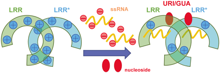
Structural studies of TLR7 and TLR8 have identified two distinct binding sites that engage with distinct types of RNA molecules and the binding to the 2nd site of the oligonucleotide allosterically increases the affinity of the 1st site toward its ligand. MD calculation and successive decomposition analysis demonstrated that the main factor of the synergy effect during the TLR7/TLR8 activation processes was the lowering of the LRR dimerization barrier and this promotion was mainly achieved by the reduction of the electrostatic repulsion with the oligonucleotide binding at the 2nd site. This was because the LRR domain monomers when polyU and ORN06 were unbound had a positive charge on each other, which caused a repulsion during rearrangement and dimerization. Since the oligonucleotides were electrically negative, the LRR domain and oligonucleotide complex approached electrically neutral, resulting in less electrical repulsion during the rearrangement and dimerization, which was thought to allow more stable dimer structures to form (Fig. 9). Reduction of electrical repulsion is effective although the location of the 2nd site is completely different between TLR7 and TLR8. Similar to TLR7 and TLR8, TLR9, one of TLR7 subfamily members, requires two different ssDNA for the efficient activation. Likewise, reduction of the electrostatic repulsion may facilitate the synergistic activation in TLR9 by the oligonucleotide binding at the 2nd site.
Conclusion
It is widely accepted that the ligand (agonist)-induced dimerization of the LRR domain of TLRs for the TLR activation. To accomplish this, TLR7 family adopts the complicated system. TLR7 and TLR8 are dual receptors of nucleoside and oligonucleotide derived from RNA degradation products, synergistically activating these receptors. Oligonucleotide is a negatively charged molecule, effectively reducing the positive charge of the ectodomain of TLR7 and TLR8 by the binding at the 2nd site, thus lowering the dimerization barrier and increasing the affinity of the 1st site for the nucleoside.
Experimental
Structure Modeling of TLR8 and TLR7 for MD SimulationsInitial models of TLR8 and TLR7 in complex with nucleoside and oligonucleotide were prepared by crystal structures. The system for TLR8 or 7 bound with nucleoside at the 1st site and oligonucleotide at the 2nd site was referred to as TLR7 or TLR8/1st site/2nd site.
In TLR8, four systems with different patterns of bound ligand/nucleotide were prepared: TLR8//, TLR8/URI/ORN06, TLR8/URI/, and TLR8/ /ORN06, where URI is uridine, ORN06 was a poly nucleotide (UUGUUGUUGUUGUUGUUGUU). These structures were modeled using the crystal structures of TLR8// (PDBID: 3W3G), TLR8/URI/ORN06 (PDBID: 4R07), and TLR8/URI/ monomer (PDBID: 4R0A). A LRR dimer of chainID of A and B was employed from PDBID: 3W3G and 4R07, and a LRR dimer of TLR8/URI/ was developed by a symmetry mate of the monomer crystal structure (PDBID: 4R0A) using PyMol.23) Missing residues, sidechains, and nucleotides in ORN06 were added using the same application used in TLR7 systems. The structure of TLR8//ORN06 was prepared by transplanting ORN06 of TLR8/URI/ORN06 after superimposingTLR8/URI/ORN06 and TLR8//. Z-loop was disconnected between residue numbers 455 and 456 for TLR7, between 443 and 444 for TLR8.
In TLR7, five systems with different lengths of poly uridine (polyU) were prepared: TLR7/GUA/U0, TLR7/GUA/U6, TLR7/GUA/U12, TLR7/GUA/U15, and TLR7/GUA/U19, where GUA was guanosine, and U19 denoted 19mer of U. These structures were modeled using the crystal structure of TLR7/GUA/U3 (PDBID: 5GMF). A LRR dimer of chainID of A and C was employed, missing residues and missing sidechains were added using MODELLER24) implemented in UCSF Chimera,25) nucleotide modeling was performed using Maestro (Schrödinger release 2018-2 for TLR7 and 2020-4 for TLR8). Mutated residues in the crystal structure were set to the that in the wildtype: Q167N, Q389N, Q488N, and Q799N. The glycosylation part was reflected in TLR7 systems as solved in the crystal structure of PDBID: 5GMF, and, in TLR8, it was reflected in one common to all the three crystal structures of PDBID: 4R07, 4R0A, and 3W3G.
The solution systems were prepared using the Solution Builder implemented in CHARMM-GUI.26,27) In the setup process of the CHARMM-GUI, missing hydrogen atoms were added, and the protonation sates of residues were set according to pKa value estimated by H++ module28) with pH 5.5 condition, the N- and C-termini were set to NH3+ and COO−, respectively, and the 5′- and 3′-termini were set to 5TER and 3 TER, respectively. The input structure was put at the center of a rectangular cell, and the cell was filled with water molecules (TIP3 water model), sodium and chloride counterions (NaCl) were added with 150 mM ion density for the TLR7 systems and 100 mM NaCl for the TLR8 systems. The different ion concentrations in TLR7 and TLR8 systems were due to the matching solvent conditions in each binding experiment.11,12)
MD SimulationsAll the MD simulations were performed using the MD program package GROMACS ver. 2019.629) under periodic boundary conditions. The CHARMM36m force field30–32) was used. An energy minimization and equilibration runs before production runs were performed according to the default setting in the Solution Builder, detailed conditions were the same as those of our previous simulations.33) One-microsecond production run with 298 K temperature was performed for each system.
Interaction energy analyses were performed using the g_mmpbsa 5.1.34,35) One hundred snapshots saved every 10 ns from the 1-μs simulation were used. Dielectric constants of the inner protein and solvent were set to 1 and 80, respectively. Here, the MM-PB/SA binding energy calculations between the LRR dimer or between the ligand and the LRR dimer were performed by the single trajectory protocol36): each component structure of a LRR monomer or the ligand was extracted from that in the complex.
Acknowledgments
This work was supported by Research Support Project for Life Science and Drug Discovery [Basis for Supporting Innovative Drug Discovery and Life Science Research (BINDS)] from the Japan Agency for Medical Research and Development (AMED) under Grant Number: JP24ama121023 (M.I.), by AMED under Grant Number: JP24fk0310517 (M.I.), Grant-in-Aid from the Japanese Ministry of Education, Culture, Sports, Science and Technology Grant Nos. 22K15046 (Z.Z.), 24K09349 (Z.Z.), 22H02556 (U.O.), 22H05184 (T.S.), 23H00366 (T.S.). CREST, JST (Grant No. JPMJCR21E4) (T.S.). This work was partly supported by the Grant for the 2021–2023 Strategic Research Promotion (No. SK202202) of Yokohama City University (M.I.). This research used the computational resources of the TSUBAME 3.0 supercomputer provided by BINDS from AMED (JP24ama121023 (M.I.)). This research also used the computational resources of the Yokohama City University, Tsurumi campus.
Conflict of Interest
The authors declare no conflict of interest.
References
- 1) Takeuchi O., Akira S., Cell, 140, 805–820 (2010).
- 2) Bell J. K., Mullen G. E. D., Leifer C. A., Mazzoni A., Davies D. R., Segal D. M., Trends Immunol., 24, 528–533 (2003).
- 3) Matsushima N., Tanaka T., Enkhbayar P., Mikami T., Taga M., Yamada K., Kuroki Y., BMC Genomics, 8, 124 (2007).
- 4) Asami J., Shimizu T., Protein Sci., 30, 761–772 (2021).
- 5) Nimma S., Ve T., Williams S. J., Kobe B., Curr. Opin. Struct. Biol., 43, 122–130 (2017).
- 6) O’Neill L. A., Bowie A. G., Nat. Rev. Immunol., 7, 353–364 (2007).
- 7) Alexopoulou L., Holt A. C., Medzhitov R., Flavell R. A., Nature (London), 413, 732–738 (2001).
- 8) Diebold S. S., Kaisho T., Hemmi H., Akira S., Reis e Sousa C., Science, 303, 1529–1531 (2004).
- 9) Heil F., Hemmi H., Hochrein H., Ampenberger F., Kirschning C., Akira S., Lipford G., Wagner H., Bauer S., Science, 303, 1526–1529 (2004).
- 10) Hemmi H., Takeuchi O., Kawai T., Kaisho T., Sato S., Sanjo H., Matsumoto M., Hoshino K., Wagner H., Takeda K., Akira S., Nature (London), 408, 740–745 (2000).
- 11) Zhang Z., Ohto U., Shibata T., Krayukhina E., Taoka M., Yamauchi Y., Tanji H., Isobe T., Uchiyama S., Miyake K., Shimizu T., Immunity, 45, 737–748 (2016).
- 12) Tanji H., Ohto U., Shibata T., Taoka M., Yamauchi Y., Isobe T., Miyake K., Shimizu T., Nat. Struct. Mol. Biol., 22, 109–115 (2015).
- 13) Tanji H., Ohto U., Shibata T., Miyake K., Shimizu T., Science, 339, 1426–1429 (2013).
- 14) Ohto U., Shibata T., Tanji H., Ishida H., Krayukhina E., Uchiyama S., Miyake K., Shimizu T., Nature (London), 520, 702–705 (2015).
- 15) Latz E., Verma A., Visintin A., Gong M., Sirois C. M., Klein D. C., Monks B. G., McKnight C. J., Lamphier M. S., Duprex W. P., Espevik T., Golenbock D. T., Nat. Immunol., 8, 772–779 (2007).
- 16) Jurk M., Heil F., Vollmer J., Schetter C., Krieg A. M., Wagner H., Lipford G., Bauer S., Nat. Immunol., 3, 499 (2002).
- 17) Hemmi H., Kaisho T., Takeuchi O., Sato S., Sanjo H., Hoshino K., Horiuchi T., Tomizawa H., Takeda K., Akira S., Nat. Immunol., 3, 196–200 (2002).
- 18) Lee J., Chuang T., Redecke V., She L., Pitha P. M., Carson D. A., Raz E., Cottam H. B., Proc. Natl. Acad. Sci. U.S.A., 100, 6646–6651 (2003).
- 19) Heil F., Ahmad-Nejad P., Hemmi H., Hochrein H., Ampenberger F., Gellert T., Dietrich H., Lipford G., Takeda K., Akira S., Wagner H., Bauer S., Eur. J. Immunol., 33, 2987–2997 (2003).
- 20) Greulich W., Wagner M., Gaidt M. M., Stafford C., Cheng Y., Linder A., Carell T., Hornung V., Cell, 179, 1264–1275.e13 (2019).
- 21) Zhang Z., Ohto U., Shibata T., Taoka M., Yamauchi Y., Sato R., Shukla N. M., David S. A., Isobe T., Miyake K., Shimizu T., Cell Rep., 25, 3371–3381.e5 (2018).
- 22) Shibata T., Ohto U., Nomura S., Kibata K., Motoi Y., Zhang Y., Murakami Y., Fukui R., Ishimoto T., Sano S., Ito T., Shimizu T., Miyake K., Int. Immunol., 28, 211–222 (2016).
- 23) DeLano W. L., CCP4 Newsletter on protein crystallography, 40, 82–92 (2002).
- 24) Šali A., Blundell T. L., J. Mol. Biol., 234, 779–815 (1993).
- 25) Pettersen E. F., Goddard T. D., Huang C. C., Couch G. S., Greenblatt D. M., Meng E. C., Ferrin T. E., J. Comput. Chem., 25, 1605–1612 (2004).
- 26) Jo S., Kim T., Iyer V. G., Im W., J. Comput. Chem., 29, 1859–1865 (2008).
- 27) Lee J., Cheng X., Swails J. M., Yeom M. S., Eastman P. K., Lemkul J. A., Wei S., Buckner J., Jeong J. C., Qi Y., Jo S., Pande V. S., Case D. A., Brooks C. L. 3rd, MacKerell A. D. J. Jr., Klauda J. B., Im W., J. Chem. Theory Comput., 12, 405–413 (2016).
- 28) Gordon J. C., Myers J. B., Folta T., Shoja V., Heath L. S., Onufriev A., Nucleic Acids Res., 33 (Web Server), 368 (2005).
- 29) Abraham M. J., Murtola T., Schulz R., Páll S., Smith J. C., Hess B., Lindahl E., SoftwareX, 1-2, 19–25 (2015).
- 30) Huang J., Rauscher S., Nawrocki G., Ran T., Feig M., de Groot B. L., Grubmüller H., MacKerell A. D. J. Jr., Nat. Methods, 14, 71–73 (2017).
- 31) MacKerell A. D. J. Jr., Feig M., Brooks C. L. 3rd, J. Am. Chem. Soc., 126, 698–699 (2004).
- 32) Klauda J. B., Venable R. M., Freites J. A., O’Connor J. W., Tobias D. J., Mondragon-Ramirez C., Vorobyov I., MacKerell A. D. J. Jr., Pastor R. W., J. Phys. Chem. B, 114, 7830–7843 (2010).
- 33) Ekimoto T., Kudo T., Yamane T., Ikeguchi M., J. Chem. Inf. Model., 61, 3625–3637 (2021).
- 34) Kumari R., Kumar R., Lynn A., J. Chem. Inf. Model., 54, 1951–1962 (2014).
- 35) Baker N. A., Sept D., Joseph S., Holst M. J., McCammon J. A., Proc. Natl. Acad. Sci. U.S.A., 98, 10037–10041 (2001).
- 36) Wang E., Sun H., Wang J., Wang Z., Liu H., Zhang J. Z. H., Hou T., Chem. Rev., 119, 9478–9508 (2019).