Articles
The Development of the Organic/Inorganic Composite Separator for Use in Secondary Zinc Batteries

2022 年 90 巻 1 号 p. 017001

詳細
2022 年 90 巻 1 号 p. 017001
The problem of dendrite growth remains unresolved in secondary zinc batteries. In order to improve the cycle life of zinc-secondary batteries, we developed an organic/inorganic composite separator that exhibits an inhibitory effect on short circuits caused by zinc dendrite growth. This separator is designed to have a sufficient ionic conductivity as well as suppression properties for preventing a short circuit. To obtain these performances, inorganic particles and hydrophobic particles are utilized which provide no extra space and no extra electrolyte for dendrite growth. Additionally, this material exhibits a good ionic conductivity. It was also confirmed that the separator we developed provided the carbon-zinc hybrid capacitor with a long life. It was also found that the carbon-zinc hybrid capacitor systems are preferable for evaluating the cyclability of separators used for zinc secondary batteries because the system has a good reproducibility. Consequently, the cycle life using the organic/inorganic composite separator was more than 10 times longer than that of conventional microporous membranes.
The changing climate and ballooning energy demands have urged societies to shift from fossil fuels to sustainable energy sources. Secondary batteries are quite important for storage and sustainable energy, thus the market has been expanding with the focus on lithium ion batteries.
On the other hand, battery accidents, such as fires, are increasing and have become a new problem of societies. Aqueous batteries that do not catch fire have thus been quite important despite their lower energy density.
As the active material of the aqueous batteries, zinc has been used as the negative material of the primary battery for a long time. The capacity density of zinc is approximately 820 mAh/g, and it enables the high-speed operation in alkaline solutions.1–4 Therefore, many scientists have tried to make secondary batteries using zinc as the negative active material. However, the main disadvantage of this battery system is its limited cycle life5,6 due to the degradation of the zinc electrode including a shape change,7,8 densification of the zinc electrode,9,10 and internal short-circuit caused by dendrite growth11,12 that have been identified. To address these issues, many improvements have been made including the zinc electrode,5,7–10,13 electrolyte,14 separator,15,16 etc. On the other hand, the crucial requirement for the market is obtaining steady performances. Sudden death caused by an internal short-circuit would not be accepted during the early stage of cycling. This problem remains unresolved. Consequently, development of a new separator has been desired so that secondary zinc batteries could be accepted in the market.
The charged zinc product produces dendrite growth which penetrates through the pores of the separator placed between the positive and negative electrodes. This penetration behavior is largely related to the number of pores or its pore size in the separator.17 For example, a smaller pore size is beneficial for suppression of the dendrite penetration, but it would provide an insufficient conductivity. A trade-off relationship was found between the ion conductivities and the durability of the cycles.
To overcome the relationship problem, separators having an organic/inorganic composite structure have been investigated. Conventional separators, such as Celgard,17 have many pores to achieve sufficient ionic conductivities. As already mentioned, it is very difficult to suppress the zinc dendrite growth into the pores during the charge/discharge cycling.
A newly produced organic/inorganic composite separator has been investigated to obtain both a suppression ability of the dendrite growth and good ionic conductivity. Consequently, the state of the electrolyte in the separator was found to be important. Extra space for dendrite growth should be reduced and an excessive electrolyte solution should be restricted. Based on these conditions, the separator consists of a mixture of inorganic particles and hydrophobic particles with a certain proportion that has been found to be applicable. It is thought that ions diffused on the inorganic particle surfaces are wet with electrolyte.
Next, a test evaluation method of the separator properties was examined. For testing separators, nickel zinc cells have been usually used,9,18–20 because a considerable cycle life can be obtained using this system. However, its reproductivity has not been discussed. It is thought that obtaining steady performances of the cells would be difficult under certain conditions. Oxygen tends to be generated on the nickel electrode during charging.21 The degradation of the nickel electrode itself is known in the nickel-zinc system.22 As a result, it was found that a carbon-zinc hybrid capacitor as a test cell is suitable for the evaluation. The reason for this is as follows.
Taking the reproductivity into account, it is thought to be very important to keep the positive electrode stable during such observations. An activated carbon electrode has an electric double layer capacity which allows a stable charge/discharge operation under various conditions including a wide temperature range, high current densities and long cycles.23,24 Therefore, it would be possible to observe the behavior of zinc dendrite growth without any other electrochemical problems.
In this paper, we present the preparation method and the configuration of the developed separator, and its effect on suppressing the zinc dendrite growth and cycle life performances using the carbon-zinc hybrid system. We suggest that the separator is quite useful to use in many kinds of the zinc secondary batteries and also in the carbon-zinc hybrid capacitor.
The preparation method of the organic/inorganic composite separator involves a two-step process. First, magnesium hydroxide with a particle size of approximately 300 nm and polytetrafluoroethylene (PTFE) were well mixed with water to produce a slurry. The PTFE was obtained from Daikin Industries. Next, the slurry was infiltrated into a non-woven fabric using the dipping method to obtain a synthetic separator having a thickness of about 100 µm, then dried in the open atmosphere. A schematic diagram of the product is shown in Fig. 1.

A schematic diagram of the separator. It is mainly formed by the hydrophilic particles; the hydrophobic particles fill the space between the hydrophilic particles. The ion conductivities are determined by the interface connection of the hydrophilic particles.
The ionic conductivity is mainly generated by the electrolyte solution existing on the magnesium particle surface. The PTFE particles work as a hydrophobic agent. This material exists among the inorganic particles due to its flexibility. It makes the amount of electrolyte in the electrode reduced in order to suppress the zinc dendrite growth. Porosity control seems to be important to obtain a good cyclability, which can be controlled by the slurry content, manufacturing process, etc.
The cell test evaluation of the separators was then performed using carbon-zinc hybrid capacitors. The configuration of the carbon-zinc hybrid capacitors was as follows. The positive electrode is mainly made of activated carbon that was obtained from AT Electrode Co., Ltd. The surface area of the activated carbon was about 1000 m2/g. The activated carbon was coated on a Ni mesh (# 100) with SBR resin as the binder. The electrode was 30 mm × 33 mm × 0.5 mm.
The negative electrode consists of two active material layers as shown Fig. 2. The first layer that contacts the separator is made of 95 wt% ZnO and 5 wt% PTFE, which were wet mixed into sheets. The particle size of the ZnO was about 300 nm. Regarding the thickness of this first layer, two types were prepared. The thicker one had a capacity density of 20 mAh/cm2 and the another one had a capasity of 10 mAh/cm2. The second layer was made using a zinc plate having a thickness of about 30 µm and a capacity of about 30 mAh/cm2. These two layers were placed on the current collector made from tin-plated copper foil to form a negative electrode. These negative electrodes were 35 mm × 35 mm.

The single cell geometry of the carbon-zinc hybrid capacitor. The thickness of the separator was about 100 µm. Because the capacity of zinc is much greater than that of the activated carbon, the total thickness of this device is dominated by the positive electrode.
The electrochemical reaction seems be proceeding on the interface. The second layer would act as a zinc reservoir to maintain the zinc potential. The overall capacity of the negative electrode is determined by the amount of zinc oxide and zinc, and the zinc ratio determines the initial SOC level.
The hybrid capacitor is designed so that the capacitance of the negative electrode is greater than that of the positive electrode. Even if the cell voltage would reach the charging upper limit or discharging lower limit, the positive side reactions on the zinc negative electrode can be completely suppressed and exhibit a stable potential behavior (Fig. 3a).
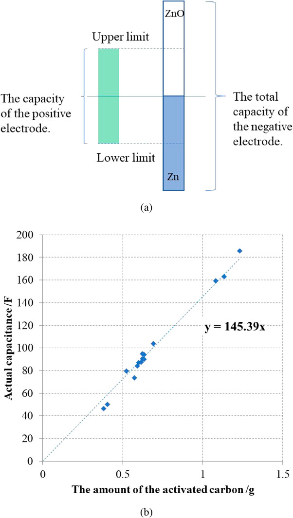
Image of the capacity formation; (a) The capacity relationship of the hybrid capacitor. (b) The actual capacity of the activated carbon in the hybrid capacitor.
The capacitance per weight of activated carbon was about 145 F per gram (Fig. 3b). The relationship between the capacitance and charge capacitance is expressed as follows.
| \begin{equation} Q (\text{mAh}) = \frac{C (\text{F})\cdot \Delta V(\text{V})}{3.6} \end{equation} | (1) |
Q (mAh) is the capacity that activated carbon can be charged and discharged, C (F) is the capacitance, and ΔV is the difference between the upper limit charge voltage and the lower limit discharge voltage. The higher ΔV produces a higher capacity, but it cannot exceed the decomposition potential of water, thus, set it was set at about 1.0 to 1.2 V.
The capacity of the positive electrode was about 1 to 2 mAh/cm2 when the voltage range was 0.4 to 1.4 V based on the Zn potential. The capacity ratio would then be about 10 : 1, which means that the ZnO layer utilization was about 10 %. The current density was calculated based on the positive electrode area as the charge-discharge reaction area was regulated by the positive electrode that was smaller.
The electrolyte solution was 6.7 mol/L KOH (6.7 M-KOH) saturated with ZnO. The ionic conductivity of the separator with the solution was measured. The separator was inserted between nickel metal electrodes and an AC voltage applied to the electrodes. (The voltage amplitude was 10 mV; the frequency was 1000 Hz. The measurement area was about 2 cm2.) To eliminate the resistance caused by the electrode interfaces and the excessive amount of electrolyte, the value of several stacked sheets was measured and the resistance per one sheet calculated. For the cycle life measurement, the electrolyte was poured into the cell and allowed to stand for 3 h. The HJ series battery charging/discharging system made by HOKUTO DENKO Co., Ltd., was used for the measurement.
Figure 4 shows the relationship between the proportion of inorganic particles and the porosity of the separator. The resistance value per unit area was also plotted in the graph. A 6.7 M-KOH solution was used to measure the resistance value. As the proportion of inorganic particles decreased, the porosity of the separator decreased, which can be expected to have a better ability to suppress the dendrite growth. However, the separator resistance increased. This led to a lower output performance. Therefore, we selected the inorganic particle ratio of 50 % as the well-balanced condition.

The dependence of the ratio between the organic/inorganic components.
The potential behavior of the carbon-zinc hybrid capacitor was evaluated. In a conventional electric double layer capacitor (EDLC), it consists of two capacitors, a positive electrode and a negative electrode. These are connected in series, and the combined capacitance of the EDLC is lower than that of the double layer capacitance of one electrode. On the other hand, in the case of a hybrid capacitor, the negative electrode undergoes an electrochemical reaction; its capacitance is determined by the double layer capacitance on the positive electrode side only. Therefore, the double capacity can be theoretically obtained and compared to an EDLC having the same type of electrode. The actual data are shown in Fig. 5. The amount of activated carbon used for the electrodes was 0.45 g. Since the capacitance of the hybrid capacitor is doubled, it can be confirmed that the slope of the potential with respect to the charge/discharge capacitance is halved. It can also be seen that the center of the charge/discharge curve is shifted by the potential difference between the carbon and zinc.

The voltage phenomena of the capacitor. The capacitance of the hybrid capacitor is twice compared to the EDCL geometry using the same activated carbon electrodes.
The typical cycling data for the carbon-zinc hybrid capacitors are shown in Fig. 6. In this measurement, the charging was carried out at constant current (40 mA/cm2) until the capacity reached 10 mAh and the discharging was also done at a constant current (40 mA/cm2) until the cell voltage reached 0.4 V. The amount of activated carbon was 0.30 g, which enable to charge more than 10 mA. The negative electrodes in the capacitors were made using the first layer having a capacity of 20 mAh/cm2 (thicker one). The charge/discharge curve only changed very slightly even after 10000 cycles. It was found that the stability of the electrodes was quite high, which led to the long-life cycles that were more than 10000 cycles.

The stability of the hybrid capacitor operation; (a) The charge-discharge curve at 100 cycles. (b) The charge-discharge curve at 10000 cycles.
Next, Fig. 7 shows the cycle performances of the hybrid capacitors having two types of separators. In this test, negative electrodes with the first layer having a capacity of 10 mAh/cm2 (thinner one) were used. The charge-discharge condition and the positive electrode were the same as those in Fig. 6. The utilization of the ZnO layer became double compared with that of the prior test, which could reduce the time of the evaluation. Regarding the separator, one was the organic/inorganic composite separator already mentioned and the other was the conventional porous separator.17 The conventional one was the hydrophilic-treated microporous membrane (Gale value of 100 to 200 s, thickness of 25 µm).

The results of the cycling properties; (a) The discharge efficiency of the carbon-zinc capacitor at the charge/discharge rate of 40 mA/cm2. (b) SEM image of the porous separator shorted by zinc dendrites.
Based on this result, when a microporous membrane is used, the zinc dendrite growth cannot be sufficiently suppressed, and an internal short circuit occurs during an early stage of the cycling test. Figure 7b shows a cross-sectional SEM photograph of the microporous membrane to confirm the behavior of the short-circuit. Zinc dendrite growth was observed. This seems to be generated from the zinc electrode side and grew toward the counter electrode through the pores in the microporous membrane, and finally inducing an internal short. In this study, the electrodes were so stable that dendrite shorting was a typical failure mode for the zinc hybrid capacitors.
Finally, the effect of the charging rate on the cycle life was examined. The cell configuration was the same as shown in Fig. 7. The discharge rate was fixed at 0.5 mA/cm2, and the charge capacity was also fixed at 1 mA/cm2. The charging rates were changed from 0.5 to 100 mA/cm2. Such a high-speed operation without any side reaction can be applied to these cells. This is due to the features of the electric double-layer capacitor as well as the high exchange current density of the zinc material.
The absolute value of the cycle life is thought to depend on the battery configuration, however, the relative merit would have a certain tendency. Figure 8 shows the life-times of the test cells under the various current densities. Based on these results, as the charging rate was increased, the life tended to be shorter overall. Based on the data, a higher charging rate would accelerate the dendrite growth. This fact allows the possibility of an accelerated test for cycling under reasonable conditions.

Comparison of the cycle life that depends on the charge current density. The cycle life was normalized by the result of the porous separator (single) at a low rate. The hybrid separator can provide more than 10 times the life cycles.
We also examined the effect of the separator thickness. The organic/inorganic composite separator has a thickness of 100 µm, which is 4 times thicker than that of the porous separator. The evaluation results of the double layer of the porous separator are shown in Fig. 8. Based on these results, stacking two microporous membranes does not significantly improve the cycle life. It was also found that the cyclability with 4 sheets of (100 µm) microporous separators was inferior to that of the organic/inorganic composite separator. This difference was more than 10 times.
For the development of zinc secondary batteries, we have developed a separator that effectively suppresses zinc dendrite growth. It was found that zinc dendrites can be effectively suppressed by using a dense structure of inorganic particles instead of the conventional separator having a porous structure. In addition, the carbon-zinc hybrid capacitor used for the evaluation is less likely to cause side reactions and has less electrode deterioration during cycling, so that it is not only effective for the separator evaluation but can also be expected to be applied as a power storage device. In order to realize a sustainable society in the future, it is important to select raw materials that are abundant and are not harmful. The newly developed separator may be applicable to configurations other than carbon-zinc capacitors, and it is speculated that it will be useful for the future development of zinc secondary batteries.
Satoshi Ogawa: Conceptualization (Lead), Project administration (Lead)
Yasuyuki Takazawa: Conceptualization (Equal), Investigation (Equal)
Hiroko Harada: Conceptualization (Equal), Formal analysis (Equal)
Mitsuzo Nogami: Conceptualization (Equal), Investigation (Equal)
The authors declare no conflict of interest in the manuscript.
S. Ogawa, Y. Takazawa, H. Harada, and M. Nogami: ECSJ Active Members