Abstract
We have developed a phase retrieval holography system using a single-board computer (SBC) with a graphics processing unit (GPU) for particle size measurement. The system comprises two cameras connected to the SBC with a GPU (Jetson NanoTM, NVIDIA®), a diode-pumped solid-state green laser, and a beam splitter. The GPU enables us to reconstruct holograms in real-time and measure particle size. The system can record the shapes and positions of particles falling in a static flow in a three-dimensional volume as two holograms generating an interference pattern. Two holograms solve the twin image problem that arises because of the lack of phase information using phase retrieval holography. We also present the requirement of this system for experimentally recording and numerically reconstructing holograms of particles. Finally, we compare the particle size distribution obtained by the system to that of conventional two-dimensional image measurement.
1. Introduction
Digital transformation (Stolterman and Fors, 2004) has changed society as a whole, as evidenced by the spread of telework and other online activities due to the COVID-19 pandemic. The use of Internet of Things (IoT) (Mattern and Floerkemeier, 2010) has also been advancing. In particular, Malik et al. (2021) reported that the use of Industrial IoT in industry has brought significant improvements and profitability in process visualization using the Raspberry Pi, an inexpensive single-board computers (SBC). In powder production, big data aggregated from each process are used for trouble detection, quality control, and determination of production conditions through artificial intelligence technology (Fujita et al., 2020).
As the processing speed of computers has improved, the amount of information obtained by optical measurement, which is used in powder production, has increased from point measurement with phase Doppler anemometry (Durst et al., 1981) to image measurement (Lichti and Bart, 2018). In addition, holography, invented by Gabor (1948), has been used for measuring particles in three-dimensional space. Gabor holography can be realized easily with a light source and a complementary metal oxide semiconductor (CMOS) camera and is insensitive to vibration because the reference and object waves are on the same optical axis.
Gabor holography is a three-dimensional microparticle measurement with a deep focal depth, involving size (Nayak et al., 2021), position (Memmolo et al., 2015), and velocity (Katz and Sheng, 2010). However, only the light intensity of the complex amplitude is recorded by the camera, which causes the twin image problem that degrades the contrast of reconstructed particles (Latychevskaia and Fink, 2007). To solve this problem, phase retrieval holography using two or more cameras has been proposed (Liu and Scott, 1987; Zhang et al., 2003). The present authors have used this method to measure microparticles (Tanaka et al., 2016), microbubbles (Kubonishi et al., 2018), and microdroplets (Nakatani et al., 2019; Tanaka et al., 2019b). However, practical usage of Gabor holography and phase retrieval holography is limited by the huge execution time for volumetric reconstruction.
Parallel processing by a graphics processing unit (GPU) accelerates holography processing (Tian et al., 2010) to be much faster than that by a central processing unit (CPU). In particle measurements, the CPU to GPU execution time ratio has been shown to be higher than 100 times (Tanaka et al., 2019a). Since 2014, NVIDIA® has released GPU-equipped SBCs for AI and IoT applications, and in 2019 it released the Jetson NanoTM as an inexpensive SBC.
This paper proposes particle size measurement using a phase retrieval holography system with a GPU-equipped SBC with theoretical and fabrication considerations. We also confirm the effectiveness of the system by comparing particle size distributions measured by it and conventional two-dimensional image measurement.
2. Recording and reconstruction of holograms in particle measurement
First, we focus on the principles of recording and reconstructing particles in three-dimensional space using Gabor holography. In particular, we discuss hologram recording conditions, the twin image problem, and particle elongation in the optical direction. Moreover, we explain the principle of phase retrieval holography used in the proposed system to suppress the twin image problem.
2.1 Recording holograms using Gabor holography
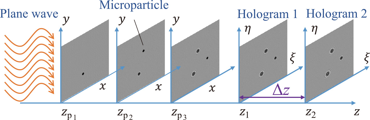
We consider the case in which particles are illuminated by a plane wave of wavelength λ as shown in Fig. 1. The complex amplitude Ψz at a distance z is formulated as
|
Ψ
z
=
exp
(
j
2
π
z
λ
)
j
λ
z
∫
∫
-
∞
∞
(
1
-
b
i
)
exp
{
j
π
λ
z
[
(
x
-
ξ
)
2
+
(
y
-
η
)
2
]
}
d
x
d
y | (1) |
where j2 = −1 is the imaginary unit. The diffracting aperture bi for the ith particle is defined as the transmittance function, namely,
|
b
i
(
x
p
i
,
y
p
i
,
z
p
i
)
=
{
1
(
(
x
-
x
p
i
)
2
+
(
y
-
y
p
i
)
2
≤
d
p
/
2
)
0
(
(
x
-
x
p
i
)
2
+
(
y
-
y
p
i
)
2
>
d
p
/
2
) | (2) |
where dp is the diameter of the particle, xpi and ypi are its center position.
Because this aperture has circular symmetry, the intensity distribution is derived by performing the integration
|
I
z
p
i
=
1
-
π
d
p
2
λ
z
p
i
sin
(
π
r
2
λ
z
p
i
)
J
1
(
π
d
p
r
λ
z
p
i
)
π
d
p
r
λ
z
p
i
+
(
π
d
p
2
4λ
z
p
i
)
2
[
2
J
1
(
π
d
p
r
λ
z
p
i
)
π
d
p
r
λ
z
p
i
]2 | (3) |
where J1 represents the first-order Bessel function. The particle information is contained mostly in the first lobe (Vikram, 1992) as shown in Fig. 2. The recording distance of a particle is limited to the range in which the lobe can be resolved, that is,
|
d
p
2
λ
<
z
1
<
d
p
W
/
2
1.22
λ | (4) |
where W/2 is the half width of the CMOS elements. Additionally, the pixel pitch Δx of the elements is also limited by the relation,
2.2 Reconstruction of holograms using Gabor holography
We reconstruct holograms explained in sec. 2.1 by introducing the convolution kernel defined as (Onural and Scott, 1987)
|
h
z
=
1
λ
z
exp
[
j
2
π
λ
z
(
x
2
+
y
2
)
] | (6) |
Eqn. (1) can be expressed compactly using the two-dimensional convolution ** as
|
Ψ
z
i
=
exp
(
j
2
π
λ
z
i
)
[
1
-
b
i
]
*
*
h
z
i | (7) |
The hologram intensity is recorded on a hologram as
|
I
z
i
=
|
Ψ
z
i
|
≈
1
-
b
i
*
*
*
h
*
z
i
-
b
i
*
*
h
z
i | (8) |
where a superscript * denotes complex conjugate, and the complex amplitude of particles is reconstructed as
|
Ψ
z
p
i
=
I
z
i
*
*
h
-
z
p
i
=
1
-
b
i
*
*
*
h
-
2
z
p
i
-
b
i
*
*
h
z
p
i | (9) |
The second and third terms on the right-hand side of Eqn. (9) lead to the virtual and real particle images. The virtual particle image causes the out-of-focus particle, as shown in the intensity line profile of Fig. 3. This is known as the twin image problem (Latychevskaia and Fink, 2007) due to the loss of phase information when the complex amplitude of the hologram is recorded by the CMOS camera.
2.3 Suppression of twin image problem using phase retrieval holography
We use phase retrieval holography, which requires two holograms separated by a distance Δz to obtain the phase information as shown in Fig. 4 (Liu and Scott, 1987; Zhang et al., 2003). This iterative phase retrieval algorithm is based on the Gerchberg–Saxton algorithm (Gerchberg and Saxton, 1972) using two holograms as intensity constraint conditions. The distance Δz between the two holograms with good convergence of the iterative process is given by Tanaka et al. (2016)
|
Δ
z
=
z
1
m
(
m
=
1
,
2
,
…
,
m
∈
ℕ
) | (10) |
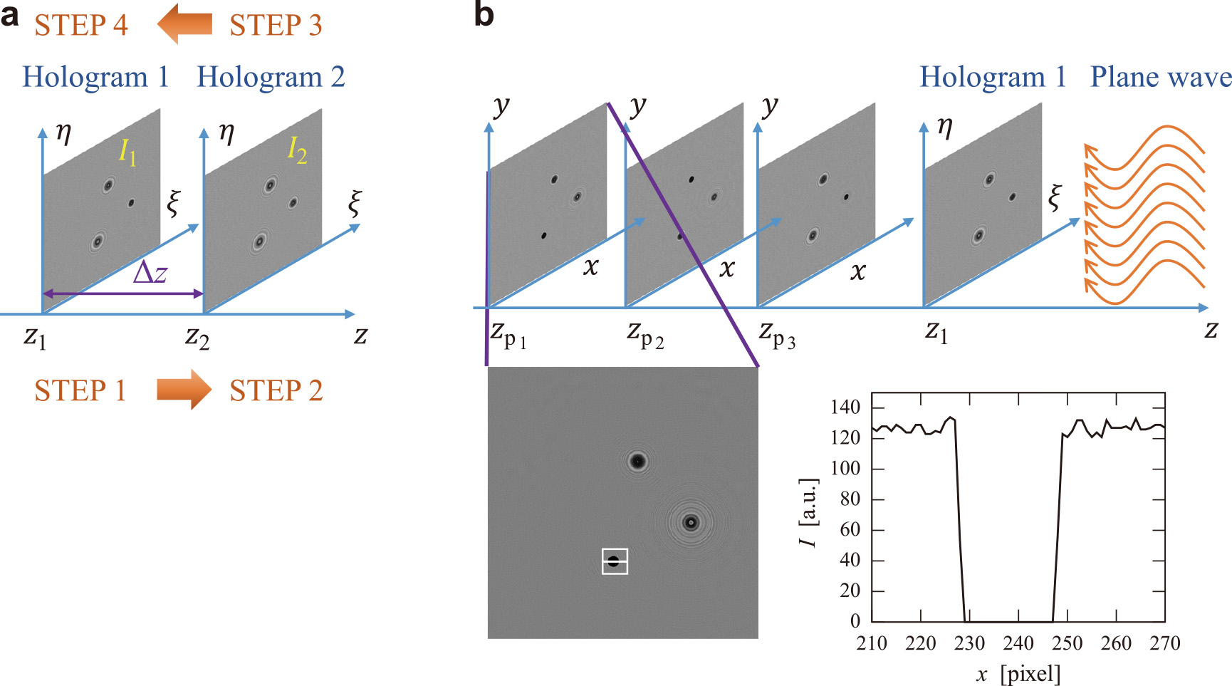
This method has an iterative process with four steps as shown in Fig. 5(a).
Step 1. Reconstruct the complex amplitude of the first hologram to the second hologram with the distance:
|
Ψ
z
2
k
=
exp
(
j
Δ
z
)
Ψ
z
1
k
*
*
h
Δ
z
=
|
Ψ
z
2
k
|
exp
(
j
φ
2
) | (11) |
Step 2. Replace the absolute value of |Ψz2k| with
I
2:
|
Ψ
z
2
k
=
I
2
exp
(
j
φ
2
) | (12) |
Step 3. Back-reconstruct the amplitude of step 2 to the first hologram:
|
Ψ
z
1
k
=
exp
(
j
Δ
z
)
Ψ
z
2
k
*
*
h
-
Δ
z
=
|
Ψ
z
1
k
|
exp
(
j
φ
2
) | (13) |
Step 4. Replace the absolute value of |Ψz1k| with
I
1:
|
Ψ
z
1
k
=
I
1
exp
(
j
φ
1
) | (14) |
where ϕ 1 and ϕ 2 are the retrieved phases at the first and second holograms, respectively. The iterative loop exits when the mode of the reconstructed image at zp3 becomes the maximum value (Tanaka et al., 2016). The virtual particle image has been removed by phase retrieval holography, as shown in the intensity line profile of Fig. 5(b) compared with Fig. 3.
2.4 Particle elongation in the optical axis direction
In addition to the twin image problem, another problem is that the reconstructed particle is elongated in the optical axis direction. To understand this problem, the complex amplitude reconstructed from the hologram formed by one particle at (xp, yp) = (0,0) on the z axis can be considered as a circular aperture on a screen (Yang et al., 2006), that is,
|
ψ
z
a
(
0
,
0
,
z
)
≈
1
-
exp
(
j
φ
) | (15) |
where ϕ is πrp2/(λz). On the other hand, the amplitude ψzo of an opaque disk is derived by using Babinet’s principle (ψza + ψzo = 0) (Born et al., 1970) as
|
ψ
z
o
(
0
,
0
,
z
)
≈
(
1
+
cos
φ
)
-
jsin
(
φ
) | (16) |
whereupon we obtain the intensity as
|
I
z
=
|
ψ
z
o
|
≈
[
1
+
cos
(
π
r
p
2
λ
z
)
]
2
+
sin
2
(
π
r
p
2
λ
z
) | (17) |
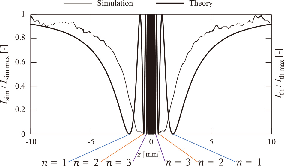
Fig. 6 shows that the intensity oscillates, with the frequency increasing toward the position of the particle. In practice, the oscillations are limited owing to the finite sensor size, as shown in the numerical plots in Fig. 6.
Particle elongation is defined by a zero-valued position that oscillates symmetrically about z = 0 in the following equation (Nakatani et al., 2019):
|
Δ
L
=
d
p
2
2
(
2
n
-
1
)
λ
′
(
n
=
1
,
2
,
⋯
,
n
∈
N
) | (18) |
Particle elongation can be expressed as dp2/(6λ) by substituting n = 2 into Eqn. (18) under the conditions of Fig. 2. Furthermore, taking this elongation into account, the recording range of Eqn. (4) can be extended as
|
d
p
2
6
λ
<
z
1
<
d
p
W
/
2
1.22
λ | (19) |
3. Holographic particle size measurement system using a GPU-equipped single-board computer
In this section, we illustrate the details of the holographic particle size measurement system using a GPU-equipped SBC (Jetson Nano, NVIDIA). Fig. 7 shows the optical setup for the phase retrieval holography system with two holograms. The laser beam (532 nm, 5 mW, Edmund®) is magnified using an objective lens (40/0.65) and converted to a collimated beam using a beam expander (TS Scorpii®, 8×, Edmund). After passing through the measurement volume (6.9 mm × 6.9 mm × 40 mm) where the particles (SP20SS, Mitsubishi Chemical Corporation) fall at their terminal velocity, the collimated light is split by a beam splitter and recorded by two CMOS cameras (BFS-U3-31S4C-BD2, FLIR, processing rates: 0.4 fps (Gabor holography) and 0.5 fps (phase retrieval holography), shutter speed: 200 μs, image size: 512 pixels × 512 pixels, cell pitch: 3.45 μm) fitted with telecentric lenses (VS-TCT05-65/S, 0.5×, WD: 65.7 mm, VS Technology®). Two cameras are installed at positions z1 = 10 mm and z2 = 20 mm under the condition of m = 1. The misalignment of a rotation and a shift in the xy plane between the two cameras was calibrated numerically within one pixel by bundle adjustment of the image distortion correction (Russ and Neal, 2016) using a calibration plate printed with random dots.

The holograms recorded by the two cameras are processed by the NVIDIA Jetson Nano with JetPack® SDK 4.6.1. Camera control and image acquisition are conducted with the Spinnaker® SDK C++ v2.5.0.80 library. The CUDA C/C++ 10.2 library and Thrust API are used for image processing and hologram reconstruction calculation using the GPU. The textbook by Shimobaba and Ito (2019) is informative, detailing GPU programming of hologram recording and reconstruction. OpenCV 4.5.4 is used to display images in GUI windows during processing. The application for bundle adjustment of the two cameras is implemented in Julia® 1.7.2.
Table 1 gives the CPU and GPU execution times for reconstruction processes using Gabor and phase retrieval holography. The CPU to GPU execution time ratio indicates that a GPU-equipped SBC is essential for early-time processing.
Table 1
Comparison of execution time comparison between CPU and GPU for Gabor and phase retrieval holography.
|
[s] |
[Ratio] |
| CPU |
GPU |
CPU/GPU |
| Gabor |
82.5 |
2.0 |
41.2 |
| Phase retrieval |
101.7 |
2.6 |
39.1 |
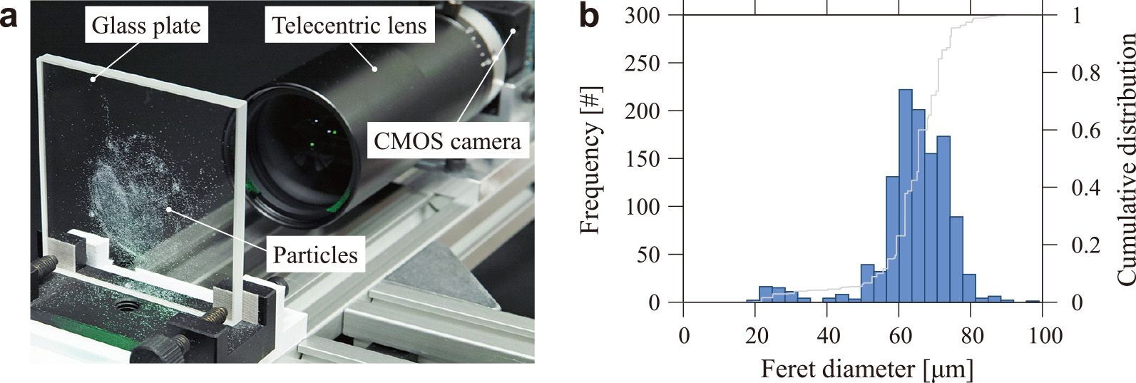
For comparison with holographic measurement, we used image measurement to determine the sizes of particles stuck to a glass plate, as shown in Fig. 8(a). We used image analysis software (Fiji 2.3.0: Schindelin et al., 2012) to apply dynamic thresholding (Prewitt et al., 1966) to the recorded image to obtain a binarized image, and we measured the particle size as the Feret diameter, as shown in Fig. 8(b).
4. Results
In this section, we report use of the fabricated system to measure particle size distributions in three-dimensional space using Gabor holography and phase retrieval holography. The effectiveness of the system is confirmed by comparing its measured distributions with that measured conventionally by two-dimensional image measurement.
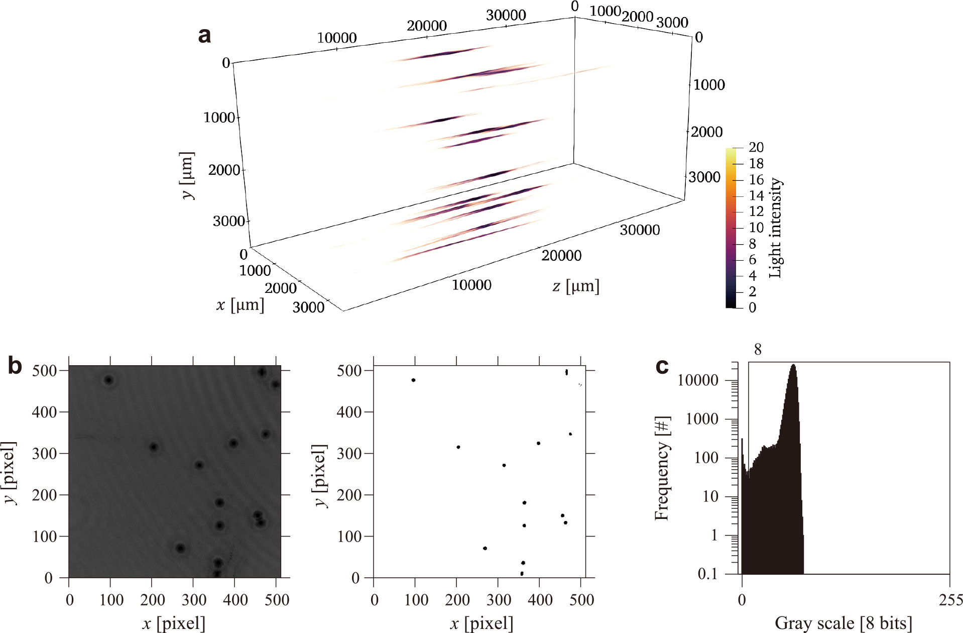
Reconstructed volumes (6.9 mm × 6.9 mm × 40 mm) of Gabor and phase retrieval holography are shown in Figs. 9(a) and 10(a), respectively. Particles are elongated along the optical axis, as shown in Eqn. (18) and Fig. 6. Although particle size can be measured from the elongation (Nakatani et al., 2019), to reduce the computational load for real-time processing, we measure the size by using the binarized image with the minimum value in the optical axis direction in the volume.
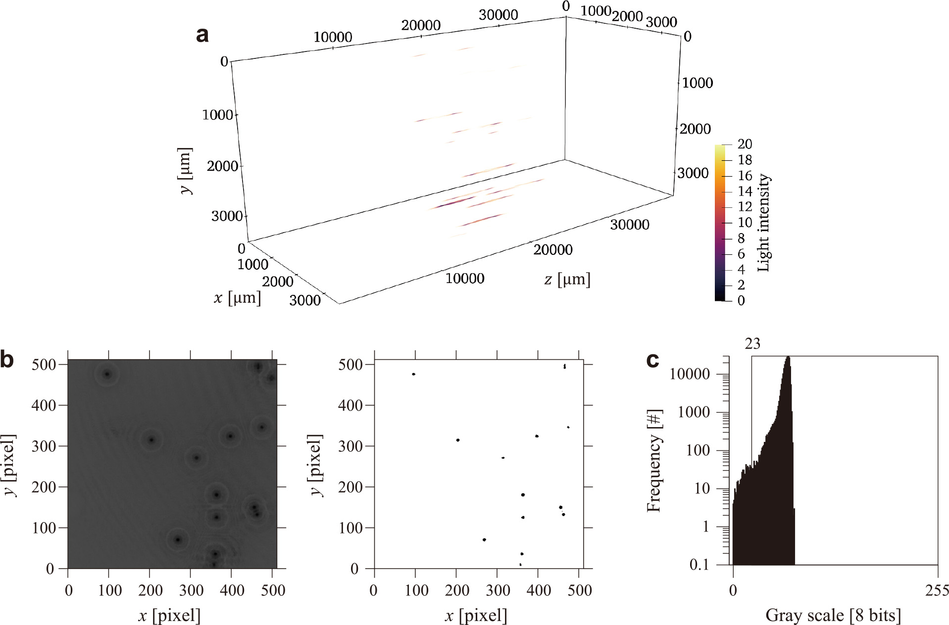
The obtained minimum-intensity image, binarized image, and intensity histogram are shown in Figs. 9(b) and 9(c) and Figs. 10(b) and 10(c), respectively. As compared in Figs. 3 and 5, phase retrieval holography, which suppresses the twin image problem, has a histogram peak at the value of zero light intensity as focused particles. In contrast, Gabor holography, which is affected by the twin image problem, has no peak in the histogram at the zero value. Consequently, Gabor holography has a larger threshold value than that of phase retrieval holography, and its binarized particle size is smaller than that of phase retrieval holography.
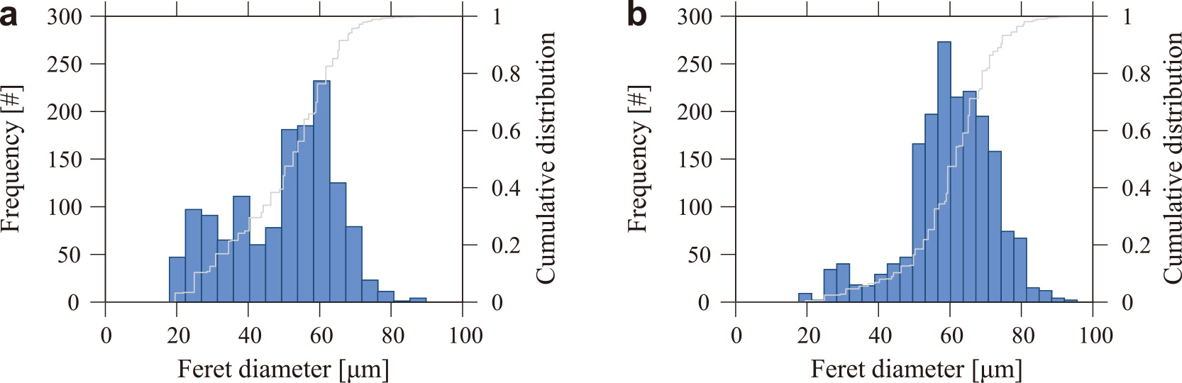
The Feret diameter is measured from the binarized images as in the image measurement of Fig. 8(b), and the particle size distributions of Gabor and phase retrieval holography are shown in Figs. 11(a) and 11(b), respectively. Gabor and phase retrieval holography have peaks of similar size. However, as mentioned above, Gabor holography has more particles below 40 μm than does phase retrieval holography because of the smaller size due to the twin image problem.
The cumulative frequency distribution functions are generated from the particle size distribution of image measurement, phase retrieval, and Gabor holography. The distributions determine the sizes corresponding to the 10th, 50th, 90th percentiles, and the span, labeled d10, d50, d90, and dspan respectively. From the values in Table 2, unlike Gabor holography, phase retrieval holography enables the measurement of almost the same distribution levels as those of image measurement.
Table 2
Particle size distributions of Feret diameter.
|
[μm] |
[-] |
| d10 |
d50 |
d90 |
dspan* |
| Image measurement |
53.9 |
65.4 |
74.3 |
0.3 |
| Phase retrieval |
44.1 |
61.7 |
74.3 |
0.5 |
| Gabor |
24.8 |
52.5 |
65.4 |
0.8 |
*
dspan = (
d90 −
d10)/
d505. Conclusion
We have illustrated a phase retrieval holography system with a GPU-equipped SBC with theoretical and fabrication considerations. This system enables real-time measurements of particle size distributions in a three-dimensional space with almost the same accuracy as that of conventional two-dimensional image measurement. The results show that the fabricated system has reached the stage of practical particle size measurements in three-dimensional space.
Data Availability Statement
The data on particle distributions by image measurement, Gabor holography, and phase retrieval holography is available publicly in J-STAGE Data (https://doi.org/10.50931/data.kona.22002518).
Acknowledgments
Our research on the phase retrieval holography system for measuring particle size distribution was supported by the Hosokawa Powder Technology Foundation (Grant Number HPTF20108).
References
- Born M., Wolf E., Bhatia A.B., Clemmow P.C., Principles of Optics: Electromagnetic Theory of Propagation, Interference and Diffraction of Light, fourth ed., Pergamon Press, Oxford, 1970, ISBN: 0521642221.
- Durst F., Melling A., Whitelaw J.H., Principles and Practice of Laser-Doppler Anemometry, Academic Press, 1981, ISBN: 0122252500.
- Fujita S., Kitamura T., Murata K., Innovation of powder process using IoT, AI, The Micromeritics, 63 (2020) 90–96. DOI: 10.24611/micromeritics.2020016
- Gabor D., A new microscopic principle, Nature, 161 (1948) 777–778. DOI: 10.1038/161777a0
- Gerchberg R.W., Saxton W.O., A practical algorithm for the determination of phase from image and diffraction plane pictures, Optik, 35 (1972) 237–246.
- Katz J., Sheng J., Applications of holography in fluid mechanics and particle dynamics, Annual Review of Fluid Mechanics, 42 (2010) 531–555. DOI: 10.1146/annurev-fluid-121108-145508
- Kubonishi A., Tanaka Y., Murata S., Observing bubbles using phase-retrieval holography, Journal of Flow Visualization and Image Processing, 25 (2018) 25–32. DOI: 10.1615/JFlowVisImageProc.2018026686
- Latychevskaia T., Fink H.W., Solution to the twin image problem in holography, Physical Review Letters, 98 (2007) 233901. DOI: 10.1103/PhysRevLett.98.233901
- Lichti M., Bart H.-J., Particle measurement techniques in fluid process engineering, ChemBioEng Reviews, 5 (2018) 79–89. DOI: 10.1002/cben.201800001
- Liu G., Scott P.D., Phase retrieval and twin-image elimination for in-line Fresnel holograms, Journal of the Optical Society of America A, 4 (1987) 159–165. DOI: 10.1364/JOSAA.4.000159
- Malik P.K., Sharma R., Singh R., Gehlot A., Satapathy S.C., Alnumay W.S., Nayak J., Industrial Internet of Things and its applications in industry 4.0: state of the art, Computer Communications, 166 (2021) 125–139. DOI: 10.1016/j.comcom.2020.11.016
- Mattern F., Floerkemeier C., From the internet of computers to the internet of things, in: Sachs K., Petrov I., Guerrero P. (Eds.), From Active Data Management to Event-Based Systems and More, Springer Berlin Heidelberg, Berlin, Heidelberg, 2010, pp. 242–259, ISBN: 978-3-642-17226-7. DOI: 10.1007/978-3-642-17226-7_15
- Memmolo P., Miccio L., Paturzo M., Di Caprio G., Coppola G., Netti P.A., Ferraro P., Recent advances in holographic 3D particle tracking, Advances in Optics and Photonics, 7 (2015) 713–755. DOI: 10.1364/AOP.7.000713
- Nakatani Y., Tanaka Y., Murata S., Estimation of spray droplet-size distribution based on droplet elongations reconstructed by phase retrieval holography, Japanese Journal of Multiphase Flow, 33 (2019) 63–70. DOI: 10.3811/jjmf.2019.004
- Nayak A.R., Malkiel E., McFarland M.N., Twardowski M.S., Sullivan J.M., A review of holography in the aquatic sciences: in situ characterization of particles, plankton, and small scale biophysical interactions, Frontiers in Marine Science, 7 (2021) 572147. DOI: 10.3389/fmars.2020.572147
- Onural L., Scott P.D., Digital decoding of in-line holograms, Optical Engineering, 26 (1987) 1124–1132. DOI: 10.1117/12.7974205
- Prewitt J.M., Mendelsohn M.L., The analysis of cell images, Annals of the New York Academy of Sciences, 128 (1966) 1035–1053. DOI: 10.1111/j.1749-6632.1965.tb11715.x
- Russ J.C., Neal F.B., The Image Processing Handbook, seventh ed., CRC Press, 2016, ISBN: 9781138747494.
- Schindelin J., Arganda-Carreras I., Frise E., Kaynig V., Longair M., Pietzsch T., Cardona A., Fiji: an open-source platform for biological-image analysis, Nature Methods, 9 (2012) 676–682. DOI: 10.1038/nmeth.2019
- Shimobaba T., Ito T., Computer Holography: Acceleration Algorithms and Hardware Implementations, 1st ed., CRC Press, 2019, ISBN: 9781482240498.
- Stolterman E., Fors A.C., Information technology and the good life, in: Kaplan B., Truex D.P., Wastell D., Wood-Harper A.T., DeGross J.I. (Eds.), Information Systems Research: Relevant Theory and Informed Practice, Springer US, Boston, MA, 2004, pp. 687–692, ISBN: 978-1-4020-8095-1. DOI: 10.1007/1-4020-8095-6_45
- Tanaka Y., Matsushi H., Murata S., Phase retrieval holography for particle measurement with GPU acceleration, Proceedings of the ASME-JSME-KSME 2019 8th Joint Fluids Engineering Conference, (2019a) V004T04A030. DOI: 10.1115/AJKFluids2019-5204
- Tanaka Y., Nakatani Y., Murata S., Visualization of spray droplets using phase retrieval holography, Proceedings of the SPIE 11051, 32nd International Congress on High-Speed Imaging and Photonics, (2019b) 69–74. DOI: 10.1117/12.2524601
- Tanaka Y., Tani S., Murata S., Phase retrieval method for digital holography with two cameras in particle measurement, Optics Express, 24 (2016) 25233–25241. DOI: 10.1364/OE.24.025233
- Tian L., Loomis N., Domínguez-Caballero J.A., Barbastathis G., Quantitative measurement of size and three-dimensional position of fast-moving bubbles in air-water mixture flows using digital holography, Applied Optics, 49 (2010) 1549–1554. DOI: 10.1364/AO.49.001549
- Vikram C.S., Particle Field Holography, 1st ed., Cambridge University Press, 1992, ISBN: 9780521018302.
- Yang W., Kostinski A.B., Shaw R.A., Phase signature for particle detection with digital in-line holography, Optics Letters, 31 (2006) 1399–1401. DOI: 10.1364/OL.31.001399
- Zhang Y., Pedrini G., Osten W., Tiziani H.J., Whole optical wave field reconstruction from double or multi in-line holograms by phase retrieval algorithm, Optics Express, 11 (2003) 3234–3241. DOI: 10.1364/OE.11.003234
Authors’ Short Biographies
Yohsuke Tanaka
Yohsuke Tanaka is an Associate Professor at the Faculty of Mechanical Engineering, Kyoto Institute of Technology. He worked for 3 years as a field engineer at Kyocera Corporation after receiving his Master’s Degree in 2002 from the Kyoto Institute of Technology. He received his Ph.D. in Engineering from Osaka University in 2008. He received fellowships (DC2) from the Japan Society for Promotion of Science from 2007 to 2008. His research interests include optical, flow, and sound measurements.
Dai Nakai

Dai Nakai received his Bachelor of Engineering from the Kyoto Institute of Technology in 2022. He has since been researching particle measurement using holography as a Master’s student at the Kyoto Institute of Technology. He is currently researching development of a machine learning-based holographic collision detection system to observe microdroplet collision in precipitation processes.

 https://ror.org/00965ax52


;%0A%09%09%09newWindow.document.open();%0A%09%09%09newWindow.document.write('<img src=%22./Graphics/41_2024002_12.jpg%22>');%0A%09%09%09newWindow.document.close();%0A%09%09)
;%0A%09%09%09newWindow.document.open();%0A%09%09%09newWindow.document.write('<img src=%22./Graphics/41_2024002_13.jpg%22>');%0A%09%09%09newWindow.document.close();%0A%09%09)