Abstract
Finite element modelling (FEM) has been extensively performed to study the flow process, the distribution of hydrostatic stress and the temperature rise in materials processed by high-pressure torsion (HPT). This overview provides a summary and a critical assessment of the most important findings obtained by means of these FEM simulations which permitted a better understanding about the microstructural evolution during processing by HPT. For convenience, FEM investigations focused on examining the nature of the HPT facility, the plastic flow, the hydrostatic pressure and the temperature evolution in HPT processing were separated into different topics. It is shown the distributions of strain, temperature and hydrostatic pressure along the disc diameter depend upon different factors such as the configuration of the HPT facility and the dimensions of the processed sample.
1. Introduction
High-pressure torsion (HPT) refers to the metal-working procedure in which a thin disc-shaped sample is severely deformed by imposing very high hydrostatic pressures and simultaneous torsional straining.1,2) This technique has been widely used to promote grain refinement down to the nanometre scale in different metals, thereby producing materials with enhanced mechanical strength and superior superplastic properties.3,4) In addition, HPT processing has been increasingly used to fabricate metal-matrix nanocomposites by consolidating powders of dissimilar materials at low homologous temperatures.5–7)
The high hydrostatic compressive stresses are needed to avoid slippage and cracking in the HPT samples.8) They are achieved using massive anvils mostly composed by tool steels, although tungsten carbide and even diamond anvils are also used when higher imposed pressures are necessary.9–11) In practice, HPT processing may be divided into two stages as illustrated in Fig. 1.12) Firstly, in the compression stage, a disc is placed at the central area of the lower anvil and an increasing load is applied at the disc surfaces until the achievement of the processing pressure. Afterwards, in the compression-torsion stage, the axial load is maintained nearly constant whilst one of the anvil rotates with a selected rotation speed imposing shear straining within the processed material.

The equivalent von Mises strain, εeq, imposed on HPT samples during the compression-torsion stage is also referred to as effective strain in different studies involving finite element modelling (FEM)13,14) and it is expressed by the following relationship:15)
| \begin{equation}
\varepsilon_{\textit{eq}} = \frac{2\pi Nr}{h\sqrt{3}}
\end{equation}
| (1) |
where
N is the number of revolutions,
r is the radial distance measured from the centre of the disc and
h is the work-piece thickness. It follows from
eq. (1) that, for a given number of turns, the sample displays an axisymmetric and heterogeneous distribution of strain and it undergoes higher torsional straining at increasing radii. Although different theoretical formulations have already been proposed for the equivalent strain in HPT,
16) it has been recently demonstrated with the aid of
in situ torque measurements that the use of
eq. (1) provides a more reasonable agreement when calculating the balance of the internal and external work during processing.
17)
In the past three decades, special attention has been dedicated to study the influence of the processing parameters and the fundamental material properties on the microstructural evolution during HPT processing.1,18,19) In general, these investigations revealed that the kinetics of grain refinement is faster at the edge of the disc compared to its centre. Nevertheless, these studies have also shown that both the hardness and grain size distribution may be substantially heterogeneous throughout the thickness of the samples depending upon the anvil design and the sample dimensions.19,20) This tendency for flow localization is not predicted in eq. (1) and this motivated the development of more advanced models to assess the plastic flow in high-pressure torsion.
Finite element modelling has been extensively used to simulate the flow process and to examine the stress state in work-pieces processed by HPT. The first report to date on FEM simulations of HPT processing was conducted using rigid anvils with unconstrained configurations together with a Cu disc represented by a two dimensional mesh constituted by elastic-plastic finite elements.21) In this study, the disc was processed up to 1/5 turn of HPT under a nominal pressure, Pnom, of 5.0 GPa. The Cu sample exhibited significant outflow and it displayed a very inhomogeneous distribution of hydrostatic pressure, with higher pressures at decreasing radial distances.
Since this pioneering study, there have been numerous investigations which successfully used the finite element method to evaluate the flow process,13,22–24) the distribution of hydrostatic stress24–28) and the temperature evolution29–31) in materials processed by HPT. The present overview aims to systematically summarise and discuss the most important contributions originated from these studies. For practical purposes, the first topic of this overview outlines the influence of the different configurations of the HPT facilities on the plastic flow during processing. The remaining topics are basically focused on quasi-constrained HPT and they survey the FEM results concerning the flow process, hydrostatic pressure and temperature evolution in samples during processing. Finally, it is drawn attention to additional material properties and new challenges which may be potentially addressed using HPT modelling.
2. HPT Facilities and Constraining Conditions
The first experiments on HPT processing were undertaken by Professor Bridgman as reported in 193532) and described in a recent review.2) In these ground-breaking studies, thin discs of different materials were simultaneously compressed and twisted using hardened steel anvils such that these samples were twisted to greater angles without fracture than in the absence of hydrostatic compressive stresses. The HPT anvils used by Prof. Bridgman did not provide any mechanical restriction to the radial flow of the work-piece which resulted in substantial reduction in the disc thickness during processing.
Since this early investigation, numerous HPT apparatus having different anvil designs have been developed. These facilities may be divided in different groups according to the geometry of the anvils and the mechanical restriction imposed to the material outflow. Therefore, HPT processing is classified into three distinct categories entitled unconstrained, quasi-constrained and constrained HPT, as illustrated in Fig. 2.23)

It is readily seen in Fig. 2 that HPT facilities with constrained configurations are constructed by placing a tube with thick walls around the work-piece. This element prevents the lateral flow of the sample which retains its overall shape after processing as demonstrated elsewhere.19) On the other extreme, the anvils do not provide any physical barrier to the sample outflow during unconstrained HPT. As a result, the extent of the material outflow depends upon the friction conditions at the interface anvil/disc and the relative size of the sample. Finally, in quasi-constrained HPT, each anvil has a shallow central depression in which the sample is located during processing. The lateral walls delineating this depression act as a mechanical restriction to the material outflow and permit the formation of only a thin ribbon at the work-piece periphery.
Finite element analyses have already been performed for unconstrained,21,25,26,33–36) quasi-constrained13,14,22,24,37–40) and constrained23,28,41–43) HPT configurations. A comprehensive study23) has recently compared the plastic flow, hydrostatic stresses and temperature distribution in Cu discs processed by one turn of HPT using the facilities shown in Fig. 2. In this investigation, FEM simulations were carried out using the commercial software DEFORM 2D 10.0 (Scientific Forming Technologies Corporation, Columbus, USA) and incorporated both the plastic straining and the heat transfer during processing. The anvils were considered as non-deformable parts and the discs were represented with meshes having ∼2200 quadrilateral elements.
Figure 3 displays the distribution of effective strain along the cross-sectional planes of samples subjected to HPT processing under different constraining conditions using a rotation rate of 1 rpm and Pnom = 1.5 GPa.23) Inspection of Fig. 3 reveals there is a more pronounced outflow and thinning in the work-piece subjected to unconstrained HPT as the anvils do not provide sufficient restriction to the radial outflow besides the frictional forces acting along the upper and lower surfaces of the sample. On the other hand, the HPT discs deformed using constrained and quasi-constrained facilities exhibited very limited outflow and almost retained their original dimensions after processing.

These FEM results also show that the plastic flow in samples processed by HPT is highly inhomogeneous, regardless of the anvil configurations. In general, the effective strain increases with increasing distances from the centre of the discs but different regions of flow localization were observed along their thicknesses. The disc processed through constrained HPT exhibits higher strains in the vicinity of its lower and upper surfaces and a region of restricted flow is formed along its lateral faces due to the friction along the contact area with the tube. It is important to note that the rotation rate of the hollow cylinder was taken as 0.5 rpm in this investigation and this resulted in a symmetrical distribution of strain in relation to the mid-thickness of the sample. By contrast, similar FEM studies performed in copper discs showed that the plastic strain tends to concentrate close to the area in contact with the rotating anvil if the lateral constraining surfaces are immobile.41–43)
It is apparent in Fig. 3 that the work-piece processed by one turn of unconstrained HPT is more severely deformed and it displays a larger area with εeq ≥ 25 by comparison with other constraining conditions. It follows from eq. (1) that the equivalent strain at a given location along the diameter of the sample is inversely proportional to its thickness. Therefore, the higher strains observed after processing using an unconstrained facility are associated with the substantial thinning of the disc which gradually increased the strain rate at a selected position along the diameter of the disc. It should be further noted that a large and thick ribbon was formed at the periphery of the sample after 1 HPT turn. This ribbon is also observed in other FEM investigations25,44) and its length may be diminished by increasing the ratio of r/h.
As evident in Fig. 3, the existence of depth shallow depressions at the surfaces of the anvils limits the extent of the material outflow during quasi-constrained HPT processing and they inhibit the reduction of the thickness of the work-piece to extreme levels. Furthermore, the distribution of effective strain along the sample thickness is more homogeneous than after processing by constrained HPT. In practice, these processing characteristics allied with relatively low torque requirements established quasi-constrained HPT as the most typical HPT configuration.19) Accordingly, various FEM studies are now available showing relevant processing features in quasi-constrained HPT and these are detailed discussed in the following topics of this overview.
In addition to the aforementioned HPT facilities and constraining conditions, 3D FEM simulations were also performed in a cone-shaped sample in the severe plastic deformation technique known as hollow cone high-pressure torsion.45) The simulation results revealed that the as-deformed cone displays a highly heterogeneous strain distribution with lower strain values at the tip of the work-piece.
3. Flow Process in High-Pressure Torsion
The theoretical relationship shown in eq. (1) does not consider the effect of compressive strains in the calculation of the equivalent strain in samples processed by HPT. However, significant hardness increments and formation of subgrains are reported for materials subjected solely to the compression stage in HPT.46,47) These results motivated the development of various FEM studies dedicated to examine the flow process and the changes in the shape of the work-piece after compression within quasi-constrained anvils.12,24,48–50)
In order to comprehensively assess the deformation behaviour in the compression stage in HPT, an elastic-plastic model was used to represent the HPT samples and the tool steel anvils were modelled as elastically deformable solids having meshes with a higher density of elements near the contact area with the disc.12,24,50) These considerations add considerable complexity to the FEM simulations which results in longer calculation times compared with FEM simulations neglecting the elastic deformation of the anvils.
Figure 4 shows the overall shape and the distribution of effective strain along the cross-sectional plane of an AZ31 magnesium alloy sample subjected to the compression stage in HPT processing.12) In this simulation, the axial load applied to the HPT disc was gradually increased until the achievement of a maximum nominal pressure of 5.0 GPa. Thereafter, the HPT facility was unloaded to permit the springback effect of the work-piece.

Inspection of the sample profile reveals that the initially flat surfaces of the HPT disc become curved after compression within the anvils. This behaviour is consistent with experimental evidences12,19) and it is attributed to the elastic distortion of the anvils during processing under high compressive stresses. It is interesting to note that this gradient in the sample thickness was also reported for samples subjected to compression within unconstrained HPT facilities25) and this may contribute to intensify the strain heterogeneity in the compression-torsion stage in HPT processing as the thickness decreases with increasing distances from the centre.
It is apparent in Fig. 7 that the AZ31 disc displays an inhomogeneous distribution of strain after quasi-constrained HPT compression. A more detailed examination of the evolution of the effective strain also reveals that the sample is plastically deformed during unloading and this is more prominent at its centre. Effective strains within the range of 0.05–0.13 are noticed at the central region of the sample after unloading and these are even higher at r > 3 mm.
Finite element analyses were also performed to investigate the flow process during the compression-torsion stage in quasi-constrained HPT. These FEM simulations used either bi-dimensional22–24,49) or three-dimensional13,14,37,39,40) models to represent the HPT facilities. The first FEM study of quasi-constrained HPT was conducted using a 3D model in which the anvils were modelled as rigid bodies and the disc having 0.8 mm in thickness and 10 mm in diameter was assumed to undergo only plastic straining using a mesh formed by ∼35,000 tetragonal elements.
Figure 5 shows the evolution of the shape of the Cu disc during the compression-torsion stage of HPT using a rotation rate of 1 rpm and Pnom = 1.0 GPa.13) In these simulations, sample slippage was prevented by considering a sticking condition for the nodes in contact with the anvils within the depression area. Also, a shear friction coefficient of 1 was assumed for simulating the contact interactions outside the depression. The FEM results show that the extruded ribbon formed at the beginning of HPT processing continuously increases with increasing rotation angles up ∼360° (1 turn). The material outflow is accompanied by significant reduction in the thickness of the sample and it extends up to the achievement of a steady-state condition where the frictional forces exerted at the contact surfaces are balanced with the extrusion forces pushing the material towards the gap between the quasi-constrained anvils.

The same study examined the evolution of the effective strain in HPT discs processed through rotation angles from 90° to 540° as depicted in Fig. 6.13) These plots show that the effective strain along the mid-section of the samples increases with increasing number of revolutions and increasing radii. The distribution of strain as a function of the distance from the centre was also calculated using eq. (1) and the theoretical predictions are consistent with the FEM calculations. After 1 HPT turn, the thickness of the sample was reduced down to ∼0.57 mm and, as a result, eq. (1) overestimates the effective strain at a given radial position for h = 0.57 mm and it underestimates the effective strain for h = 0.80 mm, as observed in Fig. 6(b). Nevertheless, it is noticed that the distributions of strain obtained through the 3D FEM simulations are not perfectly symmetrical which may be explained by inaccuracies due to constant remeshing and numerical interpolation.

The plastic flow in HPT processing is influenced by numerous variables such as the flow properties of the processed material, the dimensions of the disc, the geometry of the anvils, the applied pressure and the frictional conditions. These parameters have been analysed using FEM simulations to better understand the microstructural evolution during processing and to improve the tooling design. Figure 7 displays the distribution of effective strain rate in discs having different flow behaviour during processing by HPT under steady-state conditions.22)
It is readily seen in Fig. 7 that higher strain rates are present at the edge of the samples close to their extruded thin ribbons which corresponds to the position of minimum thickness inside the shallow depression of the anvils. A comparison of these FEM results reveals that discs with strain-hardening behaviour exhibit more uniform distributions of strain rate in the through-thickness direction. Both the perfect-plastic and the flow-softening material display higher strain rates at the mid-planes of the work-pieces and they clearly exhibit a dead metal zone at the edge of the discs. Accordingly, the microhardness distribution and the microstructure in the through-thickness direction may be heterogeneous after HPT processing as consistently verified in experiments performed in the Zn–22% Al51) and the AZ31 alloy.52,53)

More recent investigations were carried out to evaluate the influence of the flow properties on the distribution of strain within HPT discs processed using anvils with constrained configurations.54,55) Similarly to the FEM results shown in Fig. 7, these studies revealed that materials with a strain-hardening behaviour represented using a Hollomon equation exhibit a more homogenous distribution of strain rate compared with metals which reach a saturation stress after sufficient level of plastic straining. It is further indicated that HPT processing may be used to reduce the porosity of pre-compacted discs and this is more efficiently achieved in materials having a strain-hardening flow behaviour.
Finite element analyses were conducted with the aim of evaluating the influence of the dimensions of the samples on the flow process in quasi-constrained HPT.37) In these FEM calculations, perfectly-plastic discs with 10 mm in diameter and initial thicknesses varying from 0.8 to 3.8 mm were modelled in DEFORM 3D using meshes with similar densities of elements. The depth of the anvil depression was increased at the same proportion as the sample thickness in each corresponding simulation. The shear friction coefficient outside the depressions was taken as 0.3 to simulate realistic conditions for the material outflow. Figure 8 shows the distribution of instantaneous strain rate in work-pieces processed through 1/4 turn of HPT using Pnom = 2.0 GPa and a rotation speed of 1 rpm.37)

It follows from Fig. 8 that the strain rate at any selected radial position decreases with increasing sample thicknesses. Additionally, the distribution of strain rate in the through-thickness direction is more heterogeneous in thicker discs. These results are consistent with experiments undertaken using bulk samples of the Al–3Mg–0.2Sc alloy.20,56) In these studies, the Al–Mg–Sc samples had 10 mm in diameter and an initial thickness of ∼8.57 mm. The thickness was reduced down ∼8.00 mm after 1 turn and the HPT-processed cylinder displayed slower kinetics of hardening and grain refinement compared with the same material processed at equivalent conditions using samples with an initial thickness of ∼0.8 mm.57,58) It is important to note that no relevant differences in the hardness and grain size distributions were noticed in HPT samples with thicknesses varying from 0.6 to 12 mm upsized maintaining the ratio h/r within the range of 0.15 to 0.40.59) This suggests that satisfactory microstructural homogeneity may be achieved in bulk HPT samples having values of h/r < 0.4.
In quasi-constrained HPT, the angle between the bottom of the anvil depressions and the inclined lateral walls, θ, also plays a significant role in the hardness distribution19) and plastic flow in the through-thickness direction as shown in Fig. 9.39) In these simulations, the shallow depressions of the anvils have a depth of 0.25 mm and the inclinations of the lateral walls vary between 0 up to 75°.
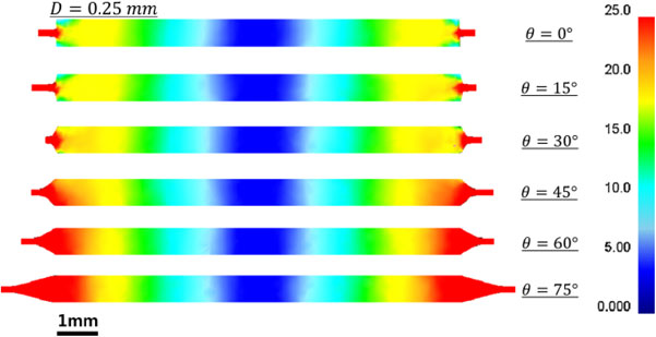
An examination of Fig. 9 reveals that the effective strain is highly heterogeneous at the edge of discs processed using anvils with depressions having θ ≤ 30°. An increase in the inclination of the walls results in more homogeneous distributions of strain in the through-thickness direction by eliminating the dead metal zones.14) On the other hand, the radial flow is facilitated by increasing the angle of the lateral walls and it leads to undesirable consequences such as higher processing torques, a more difficult control of the final dimensions of the HPT disc and excessive material loss in the form of the extruded ribbon.
In order to avoid the sample slippage during quasi-constrained HPT, the inner surfaces of the anvil depressions have high roughness and samples are processed using nominal pressures higher than three times the yield stress of the undeformed material.19) However, this condition may not be attained when processing hard metals as these eventually achieve flow stresses comparable to the yield stress of the tool steel anvils. In this case, the disc surfaces may not completely fill the micro-cavities in the shallow depressions and the material may not reach a perfect sticking condition with the anvils.
FEM simulations were used to examine the influence of friction conditions on the material flow during HPT processing.22,34,35,37,60,61) These simulations considered different friction models and coefficients for each region along the surface of the anvils. Figure 10 shows the distribution of equivalent strain in discs processed through 1/4 turn of quasi-constrained HPT using friction factors from 0 to 1.0 outside the depression area.13) It is apparent from these images that a larger and less deformed ribbon is formed in samples processed using anvils with lower friction factors corresponding to more lubricated conditions outside the depressions.

The same study demonstrated that increasing the friction coefficients outside the depression area results in higher processing torques as seen in Fig. 11.13) It is also noted that the torque needed to impose torsional straining in materials with a strain-hardening behaviour increases with increasing number of HPT revolutions and this is more significant in samples processed using less lubricated conditions. These FEM results are consistent with experimental observations in the practice of HPT processing as the area outside the depressions wears out after extensive use of the anvils. This leads to higher friction coefficients outside the shallow depressions of the anvils and higher torque requirements during processing.

The effect of friction conditions outside the anvil depressions on the material outflow in HPT processing was also analysed by means of 2D FEM simulations with a significant larger density of elements. Figure 12 shows the distribution of strain rate along the cross-section of HPT discs processed in quasi-constrained facilities considering different levels of friction at the lateral walls of the anvil depressions.22) In these simulations, a sticking condition was adopted at the inner surface of the shallow depression and the shear friction coefficient was varied from 0.1 to 0.75 at the lateral walls and at the area outside the depressions.

The results depicted in Fig. 12 demonstrate that the strain concentrates in regions at the upper and bottom corners of the disc for simulations adopting a friction coefficient of 0.1 at the inclined walls of the depressions. An increase in the friction coefficients leads to the displacement of the highly deformed areas towards the mid-section of the sample next to the extruded thin ribbon. In addition, the distribution of strain rate becomes asymmetrical if different friction coefficients are assumed for the top and bottom anvils and the plastic flow tends to concentrate in the vicinity of the anvil having a lower friction factor. It is therefore important to use pairs of anvils with depressions having similar roughness to prevent strain concentration and the generation of asymmetric mechanical properties in the through-thickness direction of HPT discs.
4. Hydrostatic Pressure in High-Pressure Torsion
The nominal pressure in HPT processing is defined as the axial load applied in the work-piece divided by the initial area of the disc. However, in most HPT configurations, the material gradually outflows increasing the area of the sample in contact with the anvils during processing. Consequently, the real hydrostatic pressure in HPT samples is expected to be somewhat lower than the estimated nominal pressure as confirmed in recent experiments.27) In addition, the distribution of hydrostatic compressive stress within the sample may depend on a series of processing parameters such as the configuration of the HPT facility and the frictional conditions at the sample interface. These aspects were considered in several FEM investigations initiated to determine the distribution of hydrostatic pressure in HPT samples during processing.13,21,23,24,26–28,49)
Figure 13 shows the distribution of mean stress in discs processed by 1/4 turn of quasi-constrained HPT processing using different nominal pressures.13) It is readily seen in these images that the distribution of hydrostatic stress is very heterogeneous along the diameter of the work-piece for all applied pressures. The hydrostatic stresses are more negative at the centre of the discs and positive mean stresses are displayed in areas of the extruded ribbon not in contact with the HPT anvils. Furthermore, an increase of the nominal pressure from 0.5 to 1.0 promotes the development of larger ribbons at the sample periphery. As a result, the HPT discs processed using higher axial loads exhibit larger volumes in which the hydrostatic pressures are not as high as the theoretical nominal pressures.

The evolution of hydrostatic stresses at the mid-section of samples processed by 1/4, 1/2 and 1 turn of HPT processing is presented in Fig. 14 for 3D FEM simulations performed using a rotation rate of 1 rpm and Pnom = 1.0 GPa.13) Inspection of these plots shows the hydrostatic stresses within the interval from about −1400 to −600 GPa are depicted in the Cu disc after 1/4 turn. These compressive stresses significantly decrease after processing to a total of 1/2 HPT revolution due to the expansion of the extruded. It is therefore indicated that the attenuation of the hydrostatic pressures in HPT samples may be prevented by using facilities with constrained configurations23) or by placing a hard ring around discs processed by HPT using a conventional quasi-constrained facility.28)

The results presented in Figs. 13 and 14 were obtained in rigid-plastic FEM calculations considering the anvils as undeformable objects.13) In more recent studies,24,49) the tool steel anvils were modelled as elastic components and it permitted the simulation of the elastic distortions of the anvils during quasi-constrained HPT processing. These simulations revealed that the inner surface of the shallow depression becomes curved which results in pronounced changes in the distribution of mean stresses at the cross-sectional plane of HPT discs. It has been consistently demonstrated that the distribution of hydrostatic pressures is more uniform than in predictions considering rigid anvils; nevertheless, the values calculated for the hydrostatic pressures in the FEM simulation remain lower than the nominal pressure.
In order to evaluate the real hydrostatic pressure in quasi-constrained HPT, discs composed of either Cu or Bi were initially processed through 5 HPT turns under a nominal pressure of ∼1.9 GPa.27) Thereafter, the same discs were compressed within the anvils using loads varying from 24.5 to 490 KN and processed by 0.5 turn of HPT. The torque evolution was recorded using strain gauges fixed to the top anvil and these measurements were used to construct plots of the torque rise after processing through additional 0.5 HPT turn as a function of the applied axial load.
The results demonstrated that there is a continuous and monotonic increment of torque with increasing loads for Cu discs processed under the described conditions. By contrast, the torque increment for Bi samples abruptly rises at the axial load of 320 KN corresponding to Pnom ≈ 4.1 GPa. Bismuth undergoes a distinct phase transformation from a rhombohedral to a harder monoclinic phase under a hydrostatic pressure of ∼2.7 GPa.62) The torque measurements indicate this phase transformation occurs when the applied load is ∼320 KN and thereby the nominal pressure significantly overestimates the mean hydrostatic pressure within the Bi disc.
In this comprehensive study, the average hydrostatic pressure for samples processed under Pnom ≈ 4.1 GPa was also predicted using 3D FEM simulations and calculated as the load divided by the total contact area in HPT discs including the extruded thin ribbon. The FEM results displayed good agreement with the pressure for phase transformation in Bi and the theoretical calculations using the new proposed method provided a better estimation for the real hydrostatic pressure in HPT processing.
5. Temperature Evolution in High-Pressure Torsion
There have been several exploratory experiments showing the temperature evolution in quasi-constrained anvils during processing by HPT.29,30,63–65) In these studies, the instantaneous temperature of the upper anvil was recorded using thermocouples placed at ∼10 mm of the inner surface of the shallow depression. It has been shown that the temperature gradually increases with increasing number of revolutions for discs composed by different materials subjected to HPT processing. Furthermore, careful measurements revealed that the maximum temperature achieved in HPT anvils depends upon the rotation rate of the anvil and the mechanical strength of the processed metal.
Nevertheless, the real temperature in the HPT disc was not directly measured in these early investigations63–65) and this motivated the development of detailed FEM models23,29,31) together with new experimental procedures66) dedicated to examine the temperature evolution in discs processed by HPT. Assuming that 90% of the plastic work is converted into heat during deformation, the temperature rise, ΔT, as a consequence of the plastic straining in materials deformed at adiabatic conditions is given by the following expression:67)
| \begin{equation}
\varDelta T = \frac{0.9}{C}\int\sigma_{\textit{eq}}\,d\varepsilon_{\textit{eq}}
\end{equation}
| (2) |
where
C is the heat capacity of the deformed material, σ
eq is the equivalent flow stress. Early attempts used
eq. (2) to predict the temperature rise in an Al–Si alloy after 5 HPT turns and they estimated temperature increments of ∼300 K and ∼140 K considering ratios of plastic work converted into heat of 0.90 and 0.35, respectively.
68) It should be noted however that the sample heating during high-pressure torsion is not adiabatic and thereby
eq. (2) substantially overestimates
ΔT.
Recent investigations used finite element modelling to provide more realistic estimations of the temperature rise in HPT processing.23,29–31) These FEM studies used eq. (2) to calculate the local amount of heat generated through torsional straining, but also incorporated the heat losses by conduction towards the HPT anvils and by convection to the environment. Figure 15 displays the distribution of temperature at different locations in the anvils composed by tool steel and in the Fe disc after processing by 10 turns of HPT at an initial temperature of 20°C using a rotation rate of 1 rpm and Pnom = 2 GPa.30)

It is readily apparent in Fig. 15 the existence of a minor temperature gradient in the Fe work-piece after 10 HPT turns. Temperatures within the interval of 50–52°C are noticed at the central area of the disc (P1) and these gradually increase with increasing radii up ∼54°C in the vicinity of the extruded ribbon (P2). It is also noted that the HPT disc consistently exhibits higher temperatures compared with the massive anvils. These results indicate that the temperature measurements carried out using thermocouples within the anvils may significantly underestimate the real temperature increase in samples processed by HPT.
The instantaneous temperature at the positions labelled P1–P4 was tracked from the beginning of HPT processing up to the completion of 10 turns (600 s) and the recorded values were used to construct plots of temperature as a function of time as shown in Fig. 15. It follows from these plots that there is an abrupt increase in the temperature of the HPT disc in the early stage of processing. This temperature increment is associated with the lack of heat dissipation through convection because there is no temperature gradient between the surfaces of the anvils and the environment in the beginning of torsional straining. Further inspection of Fig. 15 shows that the temperature at the surface of the anvils (P4) continuously increases with increasing processing time and this causes a gradual decrease in the rate of temperature rise due to the increase of the temperature gradient at the surface of the anvils.
The effect of HPT processing variables on the temperature evolution in high-pressure torsion was also analysed through numerical simulations carried out considering different materials and rotation rates as presented in Fig. 16.30) It is apparent from these plots that HPT processing eventually achieves an equilibrium condition in which the amount of heat generated by plastic work equals the sum of the various heat losses in the HPT facility and the temperature in the sample ceases to increase with increasing number of revolutions. These results also suggest that the temperature rise in HPT discs is directly proportional to the rotation speed of the anvil and the material flow stress.

Additional FEM simulations were conducted to develop a general relationship capable of predicting the instantaneous temperature in disc-shaped samples processed by HPT.31) These calculations were carried out considering different values of the angular velocity, ω, volume of the anvils, V, radius, r, and initial thicknesses, h, of the samples. Figure 17 shows the variation of the maximum temperature, ΔT, as a function of time in Ti discs processed by quasi-constrained HPT under different processing conditions.31)

The continuous lines in Fig. 17 represent results obtained from FEM simulations validated by experimental data and the dotted lines show the predictions for the temperature evolution in HPT processing determined using a general relationship derived in the same investigation.31) An examination of these plots demonstrates that the temperature rise estimated using the semi-empirical equation is consistent with the FEM results such that the difference of both predictions is within <15%. The maximum temperature increment in the HPT sample is directly proportional to the material flow stress, the angular velocity and the square of the sample radius. Accordingly, the occurrence of a significant increase in the temperature of the disc constitutes as a challenge for upscaling HPT processing which could hinder the production of HPT-processed samples in industrial scale. Nevertheless, this issue could be addressed by designing a cooling system connected to the HPT facility or by using anvils having higher heat capacities and higher volumes as the variation of temperature in HPT discs is inversely proportional to these variables.
A simplified relationship for the variation of temperature as a function of time, t, in HPT discs during processing was derived considering tool steel anvils with volumes for each anvil of ∼58,200 mm3 and samples with 10 mm in diameter as follows:31)
| \begin{equation}
\varDelta T = 0.22\sigma\omega[1 + 1.28(1-e^{-(t/482)})]
\end{equation}
| (3) |
It should be noted that the flow stress, σ, in eq. (3) corresponds to the saturation stress achieved during processing by quasi-constrained HPT and it may be estimated as the average Vickers microhardness after processing divided by 3. This general relationship permits evaluating whether there is a significant increase in the temperature of the HPT discs as higher grain sizes and decreased hardness values are obtained after processing with increasing homologous temperatures.69–74) Furthermore, it has been recent demonstrated using FEM simulations that eq. (3) gives reasonable approximations for the temperature rise in discs processed under constrained and unconstrained configurations.23)
6. Further Achievements and New Challenges in HPT Modelling
Finite element modelling has been successfully used to examine the evolution of the dislocation cell size and the dislocation density in disc-shaped samples processed by quasi-constrained HPT.40) In these simulations, the values of the shear stresses, strains and strain rates calculated in each node within the disc were incorporated to a dislocation density-based model75) to predict the microstructural changes during HPT processing. The FEM model demonstrated that the distributions of dislocation density and cell size along the diameter of the samples become more uniform with increasing number of turns. Also, these microstructural features appear to saturate after sufficient torsional straining. The FEM results for the dislocation densities and the cell sizes in HPT-processed discs were reasonably consistent with experimental measurements in Cu discs performed through transmission microscopy and X-ray diffraction analyses. Nevertheless, a more recent study revealed that more accurate estimations for these parameters may be obtained by considering the temperature rise in HPT discs in the proposed model.76)
Further accomplishments in FEM modelling of HPT processing include models for the establishment of flow vortices in HPT-processed composites,77) predictions of the evolution of texture in FCC metals,42) simulations showing the influence of formation of anisotropic lamellar structure in pearlitic steel78) and the development of an iterative model to measure stress-strain curves based on torque measurements during processing of disc-shaped samples using anvils having either constrained or unconstrained configurations.43,44)
It has been consistently shown throughout the numerous investigations summarised in this overview that the finite element method is recognized as an important mathematical tool capable of providing a better understanding concerning the flow behaviour and the microstructural evolution during HPT processing. Nevertheless, in view of the new developments in this research area, there remain numerous research questions which may be well addressed using this numerical method.
Recent comprehensive investigations used FEM simulations to examine the occurrence of phase transformations in materials subjected to high hydrostatic pressures and concomitant torsional straining within diamond anvil cells.79–86) The same approach could be potentially used to model the thermodynamics and kinetics of phase transformations during quasi-constrained HPT processing. This phenomenon has been extensively documented for pure Zr,87,88) zirconia89) and Ti27,90–95) alloys after HPT and the FEM simulations may also provide quantitative information concerning the volume fraction and distribution of the new phases and their influence on the flow process during subsequent torsional straining.
It has been consistently demonstrated that HPT processing at room temperature may be used to bind dissimilar materials96,97) and to consolidate powders composed by different materials after a sufficient number of revolutions.5–7) A Mg–10% Al2O3 composite (% in vol.) was fabricated through cold-consolidation of Mg machining chips and alumina particles using a quasi-constrained HPT facility.7) In this study, a preferential outflow of alumina particles towards the periphery of the discs was experimentally observed and this led to the formation of spiral-like structures composed by the hard-phase after one HPT turn. However, the influence of material properties and processing parameters on the flow process and solid-state reactions during powder consolidation by high-pressure torsion are not well understood and thereby FEM simulations could provide helpful insights on tailoring composites using this processing route.
In addition to the abovementioned applications, finite element analyses may be potentially applied to examine the flow process and temperature evolution in materials processed using new variations of HPT processing such as in Planar High Pressure Torsion (P-HPT)98) and in High-Pressure Tube Twisting (HPTT).99,100) This numerical method may also be utilised to model HPT processing using ring-shaped samples63,101) and most importantly to develop new designs for HPT anvils and work-pieces capable of fabricating HPT-processed materials at faster production rates.
7. Summary and Conclusions
-
(1)
Finite element modelling is well established as an effective tool to analyse the plastic flow, the microstructural evolution, the distribution of hydrostatic stress and the temperature rise in materials processed by high-pressure torsion.
-
(2)
An examination of different FEM simulations demonstrated that HPT processing using quasi-constrained facilities provides a better combination of torque requirements and dimensional control of the work-piece compared with other anvil configurations.
-
(3)
The plastic flow and the distribution of strain in HPT samples depends upon the dimensions and the flow behaviour of the processed material, the geometry of the anvils, the applied pressure and the frictional conditions during processing. The strains predicted using a theoretical formulation show a general consistency with the values calculated using finite element analyses.
-
(4)
Quasi-constrained HPT processing leads to an inhomogeneous distribution of hydrostatic pressures along the diameter of the discs. These pressures are significantly lower than the nominal pressure and they increase with decreasing radial positions.
-
(5)
The saturation temperature achieved in disc-shaped samples processed by HPT is directly proportional to the material strength, the rotation speed of the anvil and the square of the radius of the work-piece. In practice, the maximum temperature in HPT discs may be reduced using anvils with higher volumes and higher heat capacities.
Acknowledgements
This work was supported by the Serrapilheira Institute under grant number Serra-1709-17750, CNPq, FAPEMIG and CAPES-Proex.
REFERENCES
- 1) A.P. Zhilyaev and T.G. Langdon: Prog. Mater. Sci. 53 (2008) 893–979.
- 2) K. Edalati and Z. Horita: Mater. Sci. Eng. A 652 (2016) 325–352.
- 3) M. Kawasaki and T.G. Langdon: J. Mater. Sci. 49 (2014) 6487–6496.
- 4) R.B. Figueiredo, S. Sabbaghianrad, A. Giwa, J.R. Greer and T.G. Langdon: Acta Mater. 122 (2017) 322–331.
- 5) Y. Huang, P. Bazarnik, D. Wan, D. Luo, P.H.R. Pereira, M. Lewandowska, J. Yao, B.E. Hayden and T.G. Langdon: Acta Mater. 164 (2019) 499–511.
- 6) K. Edalati, S. Toh, H. Iwaoka, M. Watanabe, Z. Horita, D. Kashioka, K. Kishida and H. Inui: Scr. Mater. 67 (2012) 814–817.
- 7) M.M. Castro, P.H.R. Pereira, A. Isaac, R.B. Figueiredo and T.G. Langdon: J. Alloys Compd. 780 (2019) 422–427.
- 8) K. Edalati, Z. Horita and T.G. Langdon: Scr. Mater. 60 (2009) 9–12.
- 9) A. Jayaraman: Rev. Mod. Phys. 55 (1983) 65–108.
- 10) Y. Ma, V.I. Levitas and J. Hashemi: J. Phys. Chem. Solids 67 (2006) 2083–2090.
- 11) K. Edalati, J. Matsuda, H. Iwaoka, S. Toh, E. Akiba and Z. Horita: Int. J. Hydrogen Energy 38 (2013) 4622–4627.
- 12) P.H.R. Pereira, R.B. Figueiredo, P.R. Cetlin and T.G. Langdon: Mater. Sci. Eng. A 631 (2015) 201–208.
- 13) R.B. Figueiredo, P.R. Cetlin and T.G. Langdon: Mater. Sci. Eng. A 528 (2011) 8198–8204.
- 14) D.J. Lee, E.Y. Yoon, L.J. Park and H.S. Kim: Scr. Mater. 67 (2012) 384–387.
- 15) R.Z. Valiev, Y.V. Ivanisenko, E.F. Rauch and B. Baudelet: Acta Mater. 44 (1996) 4705–4712.
- 16) A.P. Zhilyaev, T.R. McNelley and T.G. Langdon: J. Mater. Sci. 42 (2007) 1517–1528.
- 17) J.J. Jonas, C. Ghosh and L.S. Toth: Mater. Sci. Eng. A 607 (2014) 530–535.
- 18) T.G. Langdon: Acta Mater. 61 (2013) 7035–7059.
- 19) A. Hohenwarter, A. Bachmaier, B. Gludovatz, S. Scheriau and R. Pippan: Int. J. Mater. Res. 100 (2009) 1653–1661.
- 20) G. Sakai, K. Nakamura, Z. Horita and T.G. Langdon: Mater. Sci. Eng. A 406 (2005) 268–273.
- 21) H.S. Kim: J. Mater. Process. Technol. 113 (2001) 617–621.
- 22) R.B. Figueiredo, M.T.P. Aguilar, P.R. Cetlin and T.G. Langdon: J. Mater. Sci. 47 (2012) 7807–7814.
- 23) P.H.R. Pereira, R.B. Figueiredo, P.R. Cetlin and T.G. Langdon: IOP Conf. Ser. Mater. Sci. Eng. 63 (2014) 012041.
- 24) M. Kamrani, V.I. Levitas and B. Feng: Mater. Sci. Eng. A 705 (2017) 219–230.
- 25) H.S. Kim, S.I. Hong, Y.S. Lee, A.A. Dubravina and I.V. Alexandrov: J. Mater. Process. Technol. 142 (2003) 334–337.
- 26) A. Draï and B. Aour: Eng. Struct. 46 (2013) 87–93.
- 27) K. Edalati, D.J. Lee, T. Nagaoka, M. Arita, H.S. Kim, Z. Horita and R. Pippan: Mater. Trans. 57 (2016) 533–538.
- 28) S.-H. Joo and H.S. Kim: Metall. Mater. Trans. A 47 (2016) 3473–3478.
- 29) K. Edalati, R. Miresmaeili, Z. Horita, H. Kanayama and R. Pippan: Mater. Sci. Eng. A 528 (2011) 7301–7305.
- 30) R.B. Figueiredo, P.H.R. Pereira, M.T.P. Aguilar, P.R. Cetlin and T.G. Langdon: Acta Mater. 60 (2012) 3190–3198.
- 31) P.H.R. Pereira, R.B. Figueiredo, Y. Huang, P.R. Cetlin and T.G. Langdon: Mater. Sci. Eng. A 593 (2014) 185–188.
- 32) P.W. Bridgman: Phys. Rev. 48 (1935) 825–847.
- 33) S.C. Yoon, Z. Horita and H.S. Kim: J. Mater. Process. Technol. 201 (2008) 32–36.
- 34) A. Halloumi, M. Busquet and S. Descartes: IOP Conf. Ser. Mater. Sci. Eng. 63 (2014) 012036.
- 35) M. Jahedi, M. Knezevic and M.H. Paydar: J. Mater. Eng. Perform. 24 (2015) 1471.
- 36) S. Ghaemi Khiavi and E. Emadoddin: J. Mater. Res. Technol. 7 (2018) 410–418.
- 37) R.B. Figueiredo, G.C.V. de Faria, P.R. Cetlin and T.G. Langdon: J. Mater. Sci. 48 (2013) 4524–4532.
- 38) Y. Song, W. Wang, D. Gao, E.Y. Yoon, D.J. Lee, C.S. Lee and H.S. Kim: J. Mater. Sci. 48 (2013) 4698–4704.
- 39) D.J. Lee and H.S. Kim: J. Mater. Sci. 49 (2014) 6620–6628.
- 40) D.J. Lee, E.Y. Yoon, D.-H. Ahn, B.H. Park, H.W. Park, L.J. Park, Y. Estrin and H.S. Kim: Acta Mater. 76 (2014) 281–293.
- 41) P. Wei, C. Lu, K. Tieu, G. Deng, H. Wang and N. Kong: Steel Res. Int. 84 (2013) 1246–1251.
- 42) P.T. Wei, C. Lu, K. Tieu and G.Y. Deng: IOP Conf. Ser. Mater. Sci. Eng. 63 (2014) 012045.
- 43) Y. Yogo, M. Sawamura, M. Hosoya, M. Kamiyama, N. Iwata and T. Ishikawa: Mater. Sci. Eng. A 600 (2014) 82–89.
- 44) Y. Yogo, M. Sawamura, N. Iwata and N. Yukawa: Mater. Des. 122 (2017) 226–235.
- 45) H.Y. Um, E.Y. Yoon, D.J. Lee, C.S. Lee, L.J. Park, S. Lee and H.S. Kim: Scr. Mater. 71 (2014) 41–44.
- 46) A.P. Zhilyaev, K. Oh-ishi, T.G. Langdon and T.R. McNelley: Mater. Sci. Eng. A 410–411 (2005) 277–280.
- 47) Y. Song, E.Y. Yoon, D.J. Lee, J.H. Lee and H.S. Kim: Mater. Sci. Eng. A 528 (2011) 4840–4844.
- 48) D.J. Lee, E.Y. Yoon, S.H. Lee, S.Y. Kang and H.S. Kim: Rev. Adv. Mater. Sci. 31 (2012) 25–30.
- 49) P. Verleysen, F. Van den Abeele and J. Degrieck: IOP Conf. Ser. Mater. Sci. Eng. 63 (2014) 012043.
- 50) P.H.R. Pereira, T.H.P. Costa, R.B. Figueiredo, P.R. Cetlin and T.G. Langdon: Adv. Mater. Res. 922 (2014) 592–597.
- 51) T.-S. Cho, H.-J. Lee, B. Ahn, M. Kawasaki and T.G. Langdon: Acta Mater. 72 (2014) 67–79.
- 52) R.B. Figueiredo and T.G. Langdon: Mater. Sci. Eng. A 528 (2011) 4500–4506.
- 53) M. Kawasaki, R.B. Figueiredo and T.G. Langdon: J. Mater. Sci. 47 (2012) 7719–7725.
- 54) Y. Beygelzimer, R. Kulagin, L.S. Toth and Y. Ivanisenko: Beilstein J. Nanotechnol. 7 (2016) 1267–1277.
- 55) R. Kulagin, Y. Zhao, Y. Beygelzimer, L.S. Toth and M. Shtern: Mater. Res. Lett. 5 (2017) 179–186.
- 56) Z. Horita and T.G. Langdon: Scr. Mater. 58 (2008) 1029–1032.
- 57) G. Sakai, Z. Horita and T.G. Langdon: Mater. Sci. Eng. A 393 (2005) 344–351.
- 58) P.H.R. Pereira, Y. Huang and T.G. Langdon: Mater. Sci. Forum 879 (2017) 1471–1476.
- 59) A. Hohenwarter and R. Pippan: Metall. Mater. Trans. A 50 (2019) 601–608.
- 60) Y. Song, W. Wang, D. Gao, E.Y. Yoon, D.J. Lee and H.S. Kim: Met. Mater. Int. 20 (2014) 445–450.
- 61) A. Ben Kaabar, A. Aoufi, S. Descartes and C. Desrayaud: IOP Conf. Ser. Mater. Sci. Eng. 194 (2017) 012044.
- 62) P.W. Bridgman: Rev. Mod. Phys. 18 (1946) 1–93.
- 63) Y. Harai, K. Edalati, Z. Horita and T.G. Langdon: Acta Mater. 57 (2009) 1147–1153.
- 64) Y. Mine, Z. Horita and Y. Murakami: Acta Mater. 58 (2010) 649–657.
- 65) Y. Todaka, M. Umemoto, A. Yamazaki, J. Sasaki and K. Tsuchiya: Mater. Trans. 49 (2008) 7–14.
- 66) K. Edalati, Y. Hashiguchi, P.H.R. Pereira, Z. Horita and T.G. Langdon: Mater. Sci. Eng. A 714 (2018) 167–171.
- 67) W.F. Hosford and R. Caddell: Metal Forming: Mechanics and Metallurgy, Third Ed., (Cambridge University Press, New York, 2007).
- 68) A.P. Zhilyaev, J.M. García-Infanta, F. Carreño, T.G. Langdon and O.A. Ruano: Scr. Mater. 57 (2007) 763–765.
- 69) Y. Harai, M. Kai, K. Kaneko, Z. Horita and T.G. Langdon: Mater. Trans. 49 (2008) 76–83.
- 70) G.B. Rathmayr and R. Pippan: Acta Mater. 59 (2011) 7228–7240.
- 71) Y. Huang, R.B. Figueiredo, T. Baudin, F. Brisset and T.G. Langdon: Adv. Eng. Mater. 14 (2012) 1018–1026.
- 72) P. Ghosh, O. Renk and R. Pippan: Mater. Sci. Eng. A 684 (2017) 101–109.
- 73) P.H.R. Pereira, Y. Huang and T.G. Langdon: J. Mater. Res. Technol. 6 (2017) 348–354.
- 74) P.H.R. Pereira, Y. Huang and T.G. Langdon: IOP Conf. Ser. Mater. Sci. Eng. 194 (2017) 012013.
- 75) L.S. Tóth, A. Molinari and Y. Estrin: J. Eng. Mater. Technol. 124 (2002) 71–77.
- 76) H. Parvin and M. Kazeminezhad: Mater. Sci. Technol. 32 (2016) 1218–1222.
- 77) R. Kulagin, Y. Beygelzimer, Y. Ivanisenko, A. Mazilkin and H. Hahn: Procedia Eng. 207 (2017) 1445–1450.
- 78) N. Larijani, C. Kammerhofer and M. Ekh: J. Mater. Process. Technol. 223 (2015) 337–343.
- 79) V.I. Levitas and O.M. Zarechnyy: EPL 88 (2009) 16004.
- 80) B. Feng, V.I. Levitas and O.M. Zarechnyy: Comput. Mater. Sci. 84 (2014) 404–416.
- 81) B. Feng, V.I. Levitas and R.J. Hemley: Int. J. Plast. 84 (2016) 33–57.
- 82) B. Feng and V.I. Levitas: J. Appl. Phys. 119 (2016) 015902.
- 83) B. Feng and V.I. Levitas: Int. J. Plast. 92 (2017) 79–95.
- 84) B. Feng and V.I. Levitas: Mater. Sci. Eng. A 680 (2017) 130–140.
- 85) B. Feng, V.I. Levitas and M. Kamrani: Mater. Sci. Eng. A 731 (2018) 623–633.
- 86) B. Feng, V.I. Levitas and W. Li: Int. J. Plast. 113 (2019) 236–254.
- 87) M.T. Pérez-Prado, A.A. Gimazov, O.A. Ruano, M.E. Kassner and A.P. Zhilyaev: Scr. Mater. 58 (2008) 219–222.
- 88) K. Edalati, Z. Horita, S. Yagi and E. Matsubara: Mater. Sci. Eng. A 523 (2009) 277–281.
- 89) K. Edalati, S. Toh, Y. Ikoma and Z. Horita: Scr. Mater. 65 (2011) 974–977.
- 90) K. Edalati, T. Daio, M. Arita, S. Lee, Z. Horita, A. Togo and I. Tanaka: Acta Mater. 68 (2014) 207–213.
- 91) A. Panigrahi, M. Bönisch, T. Waitz, E. Schafler, M. Calin, J. Eckert, W. Skrotzki and M. Zehetbauer: J. Alloys Compd. 628 (2015) 434–441.
- 92) H. Shahmir and T.G. Langdon: Mater. Sci. Eng. A 667 (2016) 293–299.
- 93) H. Shahmir and T.G. Langdon: Mater. Sci. Eng. A 704 (2017) 212–217.
- 94) A.R. Kilmametov, Y. Ivanisenko, A.A. Mazilkin, B.B. Straumal, A.S. Gornakova, O.B. Fabrichnaya, M.J. Kriegel, D. Rafaja and H. Hahn: Acta Mater. 144 (2018) 337–351.
- 95) W. Zhang, H. Ding, P.H.R. Pereira, Y. Huang and T.G. Langdon: Mater. Sci. Eng. A 732 (2018) 398–405.
- 96) B. Ahn, A.P. Zhilyaev, H.-J. Lee, M. Kawasaki and T.G. Langdon: Mater. Sci. Eng. A 635 (2015) 109–117.
- 97) M. Kawasaki, J.-K. Han, D.-H. Lee, J. Jang and T.G. Langdon: J. Mater. Res. 33 (2018) 2700–2710.
- 98) A. Hohenwarter and R. Pippan: Adv. Eng. Mater. 20 (2018) 1800050.
- 99) L.S. Tóth, M. Arzaghi, J.J. Fundenberger, B. Beausir, O. Bouaziz and R. Arruffat-Massion: Scr. Mater. 60 (2009) 175–177.
- 100) J.T. Wang, Z. Li, J.T. Wang and T.G. Langdon: Scr. Mater. 67 (2012) 810–813.
- 101) Y. Harai, Y. Ito and Z. Horita: Scr. Mater. 58 (2008) 469–472.

