Abstract
In the present article, recent reports on microstructure and mechanical properties in SPDed Fe–Ni–Co–Ti and Fe–Ni–Al–C alloys are overviewed. The chemical compositions in these alloys have been determined to have lattice softening where the elastic constant C′ goes to a very small value. The alloys with lattice softening were processed with severe plastic deformation, SPD, to raise the strength. Here, SPD includes severe cold working by rotary swaging, cold rolling and high-pressure torsion. These alloys have been reported to have ultrahigh strength along with good tensile ductility and the balance of strength and ductility is better than that in conventional high-strength steels. Microstructural development during the SPD process and the relation between microstructure and mechanical properties in SPDed alloys are summarized. The phase stability of γ has an important role in the microstructural development during SPD process and deformation behavior in the subsequent mechanical testing. The untransformed γ has a potent capability for plastic deformation where strain-induced transformation and deformation twinning can be expected to occur during mechanical tests after SPD processing. Simultaneous activation of these deformation mechanisms during plastic deformation would be a common feature in the lattice softened alloys, but the effects of alloying elements and phase stability on the deformation behavior have not been understood yet.

1. Introduction
High-strength metallic materials are required for various industrial products and many researchers have made a great effort to achieve higher strength along with higher ductility in metallic materials. Most of the researches focus on novel methods for strengthening, but high strength materials often tend to have poor ductility. They can not be used practically since they are not ductile enough to be manufactured into the industrial products or to satisfy specifications required for the reliability of the products in service. This article overviews recent reports1–9) on high strength Fe based lattice softened alloy with good ductility processed with severe plastic deformation (SPD). Here, SPD includes severe cold rolling, swaging and high-pressure torsion (HPT).
The Fe based lattice softened alloys have been designed based on the knowledge obtained in a Ti-based lattice softened alloy. In 2003, Saito et al. have reported that Ti-base alloy, Gum Metal,10) has very high strength near ideal strength along with sufficient ductility. The alloy has been practically used for eye-glass flames, sporting goods, wires for dental uses, etc. Gum Metal shows unique characteristics in plastic deformation where intense plastic localization does not lead to plastic instability. One of the characteristic features is “Giant fault” which is inhomogeneous shear developing in the interior of grains and exerts large stress concentration to grain boundaries. The large stress concentration results in large local plastic deformation near the giant fault, which does not result in local initiation of cracks. The capacity for local plastic deformation seems to be large enough to accommodate the stress concentration in the localized area near grain boundaries.
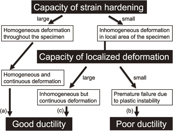
Figure 1 shows the effect of the strain localization on ductility of metallic materials. If the capacity of strain hardening is large enough, the material can deform to a large strain and show good ductility, which is indicated as route (a) in the figure. Here we compare the cases in the conventional high strength materials and Gum Metal. Generally, high strength metallic materials have poor strain hardenability, which leads to plastic instability at early stage of plastic deformation and premature failure with poor ductility, as shown in route (b). Gum Metal also has poor strain hardenability, which leads to intense strain localization like Giant fault. However, such strain localization is accommodated by local plastic deformation and does not result in premature failure, as shown in route (c). The authors consider that this might be the reason for the good ductility in Gum Metal. The origin of this ductile mechanism in Gum Metal has been considered to be related to lattice softening, where the elastic constant C′ goes to a very small value.11,12) Hence, we have investigated similar iron-based alloys with lattice softening. In the present article, we describe the lattice softening in Fe–Ni systems, and overview the researches on mechanical properties in SPDed Fe–Ni–Co–Ti and Fe–Ni–Al–C alloys reported in recent years.
2. Alloy Designing to Utilize Lattice Softening
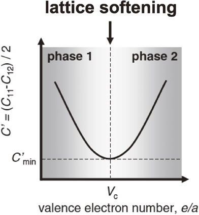
Here, we define the term lattice softening as elastic anisotropy with significant elastic softening along specific crystal orientations. Such elastic softening is often observed in the crystals at high temperature just below melting point, since the atomic bonding goes significantly weak at the transformation from solid to liquid. Even at room temperature, elastic softening can be realized in some alloy systems by choosing specific chemical compositions. The atomic arrangement of Gum Metal was designed by careful choice of the ratio e/a, where its crystal structure is unstable and elastic lattice softening occurs in specific crystallographic orientations. Figure 2 shows the schematic relation between the lattice softening and the crystal stability. For the case of Ti-base alloy, Gum Metal, phase 1 and 2 are hexagonal close-packed and body-centered cubic (bcc) structure, respectively, and C′ is minimized to 12.5–13.5 GPa at critical valence electron number, Vc, of 4.24.13) The Fe–Ni alloy system has similar lattice softening; the phase stability lies at the boundary where phase 1 and phase 2 are bcc and face-centered cubic (fcc) structure, respectively. In the Fe–Ni binary system, C′ is minimized to 21.5 GPa at critical valence electron number, Vc, of 8.75.14)
What happens in the alloy with low C′? Elastic softening in C′ results in reduced elastic moduli along specific crystallographic orientations. Shear moduli in the crystalline solids with cubic crystal structures are given by
| \begin{equation}
G_{001} = C_{44}
\end{equation}
| (1) |
| \begin{equation}
G_{011} = C' = (C_{11}-C_{12})/2
\end{equation}
| (2) |
where
G001 and
G011 are shear moduli along ⟨001⟩ on {011} and ⟨011⟩ on {011}, respectively. In bcc crystals,
G111, shear modulus along ⟨111⟩ on {011}, {112}, {123}, given by
| \begin{equation}
G_{111} = 3C_{44}(C_{11}-C_{12})/(C_{11}-C_{12}+4C_{44})
\end{equation}
| (3) |
is also important because these orientations are the easy slip directions in bcc crystals.
15) On the other hand, the easy slip direction in fcc crystals is known to be ⟨011⟩ on {111}, and shear modulus along this orientation,
G⟨011⟩{111}, is as follows.
5)
| \begin{equation}
G_{\langle 011\rangle\{111\}} = 3C_{44}(C_{11}-C_{12})/(C_{11}-C_{12}+4C_{44})
\end{equation}
| (4) |
Note that the right side of formula is the same in (3) and (4), and the lattice softened alloys with small
C′ value are elastically softened in the easy slip directions both in bcc and fcc crystals. This means that lowering
C′ is a common strategy to obtain the alloy with low shear modulus in easy slip directions.
Generally, merely reducing the elastic modulus results in just lowering the limit of strength, since the ideal shear strength is generally around 10% of the shear modulus in easy slip directions. In order to develop an alloy with high strength and high ductility, we should consider how the strength level of the materials can be raised under the limit of strength and also which kind of deformation mechanisms can operate at that range of strength. One possible strategy is activation of numbers of deformation mechanisms by raising the applied stress during deformation. In the following sections, the SPDed Fe–Ni base alloys with lattice softening are overviewed where SPD is utilized to raise the strength level.
3. Fe–Ni–Co–Ti Alloys
In this section, the reports on Fe–Ni–Co–Ti alloys are overviewed. The Fe–19Ni–34Co–8Ti alloy is the first iron-based high strength alloys the authors designed in 2009 from the view point of lattice softening. It had been reported by Cesari et al.16) that significant lattice softening occurs in an Fe–Ni–Co–Ti alloy with transformation temperature near ambient temperature. Table 1 summarizes chemical compositions and process conditions in the alloys described in this section. Here, e/a is calculated as averaged valence electron number per atom.

Table 1 Chemical compositions in mol% and process conditions for Fe–Ni–Co–Ti alloys.
The authors had reported that the Fe–19Ni–34Co–8Ti, alloy No. 1 in Table 1, shows very high strength along with sufficient tensile elongation after processed with HPT for 10 turns under a compression stress of 6 GPa.1) As shown in later in this section, we found that the critical valence electron number for lattice softening, Vc, in the Fe–Ni–Co–Ti system lies at 8.40, and determined the chemical composition as Fe–19Ni–34Co–8Ti. Initial crystal structure of solution treated specimen before HPT is γ phase with fcc structure, which totally transforms into α′ phase with bcc structure by HPT. The HPT process also changes the grain structure of the alloy; initial grain size of the alloy was about 200 µm, but the significant grain refinement by HPT resulted in very fine grain structure with grain size of 20–50 nm along with high density of crystal defects inside the grains. Such significant structural refinement was observed throughout the specimen.
Tensile tests of the HPTed Fe–19Ni–34Co–8Ti alloy revealed its ultrahigh strength and good ductility. The alloy started to deform plastically after the elastic limit and the applied stress increased up to maximum of 2.7 GPa and decreased to fracture point at 2.2 GPa with a total elongation to fracture of 9.4%. The significant grain refinement along with high density of defects would be responsible to suppress the dislocation motion up to ultrahigh stress level. Fracture surface was characterized by very fine and uniform distribution of microdimples, which confirmed substantial amount of local plastic deformation accompanied by ductile process of microvoid evolution and coalescence during the fracture process. The elastic deformability was as much as 1.8%, which is similar to that in Gum Metal, and considerably higher than conventional metallic materials with less than 0.5%.
The authors also examined the effect of alloy compositions on the lattice softening using Fe–Ni–Co–Ti alloys having e/a ranging from 8.29 to 8.53.2) The result of tensile tests revealed that Young’s modulus was minimized at an e/a value of around 8.4 where the martensitic transformation temperature was at ambient temperature. This indicates that the electronic state of the Fe–Ni–Co–Ti alloy has a strong relation with e/a and the largest lattice softening occurs at the e/a of 8.4. In relation to the phase stability, microstructural evolution during HPT process was investigated by electron backscatter diffraction (EBSD) analysis using the Fe–18.1%Ni–34.9%Co–9.3%Ti, alloy No. 2 in Table 1.3) In the early stage of HPT straining, equivalent strain up to 22.6, lamellar-shaped α′ phase was induced by martensitic transformation in γ grains. Subsequent straining in the later stage of HPT, equivalent strain over 22.6, generated very fine α′ grains with the size from 20 to 50 nm. The hardness of the alloy increased from 3.5 to 7 GPa in the early stage of straining during HPT, and this significant hardening in the early stage was considered to be related to the increase in dislocation density accompanied by the transformation from γ to α′. The hardness subsequently increased up to 8 GPa in the later stage of straining, and this moderate hardening was considered to be due to refinement of grains with some dynamic structural recovery.
Edalati et al. tried to improve the mechanical properties of Fe–Ni–Co–Ti alloys, alloys No. 3, 4 in Table 1, by post heat treatment after the HPT processing. They observed nanotwinned structures in the HPT-processed samples that were subsequently annealed at 473 and 773 K for 3.6 ks. In the HPT-processed sample after the annealing, they observed many nanotwins within the nanograins; the width of nanotwins after annealing at 473 K is larger than that after annealing at 773 K. The tensile strength after annealing at 473 K was 2.3 GPa for Alloy 3 with γ + α′ phases, and was higher, 3 GPa, for Alloy 4 with α′ phase. The elongation to failure was 20% for Alloy 3 and 10% for Alloy 4, with a uniform ductility of 2% for both materials. The difference between the ductility of Alloys 3 and 4 should be due to the difference in the fractions of γ and α′ phases and the effect of chemical composition on the inherent ductility of the α′ and γ phases. In addition, they found little ductility in the specimens of these two alloys after annealing the two alloys at 773 K. They concluded that the brittle behavior is due to the elemental distribution and extremely small width of twins. Since the compositions of these alloys were selected to have a lattice softening and resultant high ductility, the changes in the composition by the elemental distribution changes the elastic properties of the alloy.
3.2 Strengthening by swaging
In addition to the HPTed specimens, the authors recently examined the mechanical properties in the Fe–Ni–Co–Ti alloy, alloy No. 5 in Table 1, processed with rotary swaging at room temperature. The reduction of swaging is 87% in cross sectional area, and the cold swaged bar was machined into round tensile test pieces with 2.4 mm in diameter. The tensile tests were performed at room temperature. Figure 3 shows an example of stress vs. strain curve obtained by the tensile tests. Here, the specimen shows very high 0.2% proof stress near 3 GPa, and the stress starts to decrease just after yielding and plastic deformation continues until the specimen fails at a total elongation of 4.3%. Figure 4 shows the fracture surface of the tensile specimen, showing cup-cone type ductile fracture behavior characterized by well-developed dimples in the center area of the fracture surface.
3.3 Comparison in mechanical properties of SPDed Fe–Ni–Co–Ti
The relation between ultimate tensile strength and tensile elongation is plotted in Fig. 5, where the number indicated at each plot corresponds to the alloy number shown in Table 1. The alloys No. 1, 4, 5 have UTS over 2.5 GPa and total elongation of 4–10%. The alloy No. 3 has slightly lower UTS and the elongation of as much as 20%. These combinations of UTS and total elongation are far better than those in conventional high-strength steels ever reported. The precipitation hardened Fe–Mo base laboratory alloys17,18) have very high UTS of around 3.6 GPa but poor ductility below 1% of tensile elongation. Some of the cold drawn thin wires19,20) have the better combination of strength and ductility than the Fe–Mo alloys but their ductility is only 3% of elongation.

Figure 6 shows the effect of equivalent strain during the SPD process on the ultimate tensile strength. Here, although numbers of the plots are not enough to understand the detailed tendency, even the equivalent strain of around 2, in swaged specimen in alloy No. 5 in Table 1, can achieve as much as 3 GPa of UTS. This agrees with the result where the significant strengthening was observed due to the increase in dislocation density accompanied by the γ to α′ transformation in the initial stage of HPT processing.3) The swaged material has ultrahigh strength, but the ductility is smaller than HPTed material. The reason for this smaller ductility in the swaged specimen is unknown, and further research is required to clarify the effect of method of cold working, amount of applied strain, and also the effect of each alloying element on the mechanical properties in SPDed Fe–Ni–Co–Ti alloys.
4. Fe–Ni–Al–C Alloys
In this section, the reports on Fe–Ni–Al–C alloys are overviewed. The authors have been interested in this alloy system, since the SPDed Fe–Ni–Co–Ti alloys described in the previous section have very attractive mechanical properties but the cost for manufacturing these alloys is unfortunately very high due to high amount of cobalt content, 32–35 mol%. Table 2 summarizes chemical compositions and process conditions in the Fe–Ni–Al–C alloys described in this section.5–9) The chemical compositions were indicated in mass% in the original papers, but they are converted into the one in mol% in Table 2, in order to enable easier comparison with the compositions of Fe–Ni–Co–Ti alloys in Table 1. In addition, e/a in Table 2 is calculated as averaged valence electron number per atom from the chemical compositions of iron and nickel; the effect of addition of aluminum and carbon on the electronic structure of the alloys are neglected in the calculation of e/a here. This is because the effects of these elements on the electronic structure in this alloy system is unknown, and the exact estimation of electronic structure requires critical studies by ab initio calculations, etc. Hence, the e/a values shown here are not strict ones and just used as tentative parameters to indicate the phase stability. According to Kajiwara et al.,21) the martensite transformation starting temperature of Fe–(20–22)%Ni–(4–6)%Al–0.4%C (in mass%) is approximately the ambient temperature. The Fe–Ni–Al–C alloys in Table 2 also have chemical compositions similar to the alloy reported by Kajiwara et al., and the critical valence electron number for lattice softening, Vc, in this alloy system is considered to be at 8.50.
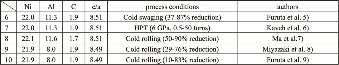
Table 2 Chemical compositions in mol% and process conditions for Fe–Ni–Al–C alloys.
The authors reported that Fe–22Ni–11.3Al–1.9C, alloy No. 6 in Table 2, had very high strength along with excellent tensile elongation after swaged by 87%.5) We examined the effect of amount of reduction in cold working on the tensile properties in this alloy. By increasing the amount of the reduction up to 87%, the yield stress (YS) increased from 0.4 GPa before cold working to approximately 2 GPa, where the upper yield point appeared in the stress-strain curves of the cold worked specimens. In addition, the most important thing was that cold working did not reduce the tensile ductility; the specimen cold worked by 87% with a YS of 2 GPa exhibited a uniform elongation (UE) of over 20% and finally failed after the total tensile elongation over 25%. Microstructure just after the solution treatment was basically composed of an fcc phase matrix (γ) with a grain size of 30–50 µm and the second phase with a size of less than 10 µm. The microstructure after cold working consisted of a heavily deformed structure in γ grains; an inhomogeneous microstructure of the γ grains consists of a mixture of two areas, namely, one area with a small grain size of 20–50 nm and the other area with a large grain size of 2–5 µm, where second-phase particles were also observed. In addition, the larger γ grains had lamellae of very thin domains of approximately 10 nm in size with deformation twins. Such ultrafine microstructure accounted for the strengthening associated with cold working. Regarding the excellent ductility, the relationship between true stress (σ) and true strain (ε) in the cold-worked specimen, along with dσ/dε was considered to evaluate the strain hardening behavior during tensile deformation. The strain-hardening capacity of the cold-worked specimen is high enough to avoid plastic instability during tensile deformation under the condition of dσ/dε > σ.
Ma et al. also reported that a Fe–Ni–Al–C, alloy No. 8 in Table 2, exhibited ultrahigh strength along with excellent ductility after cold rolling by 90%.7) They confirmed that similar strengthening can be also achieved by severe cold rolling using the alloy with almost identical composition to alloy No. 6 in Table 2. In addition, they made some analyses on the deformation mechanism and revealed that obvious phase transformation was observed during the tensile loading for the cold-rolled samples, and the amount of phase transformation was found to increase with increasing cold-rolling reduction, resulting in excellent tensile ductility in the severely deformed alloy. They also insisted that the back-stress hardening played an important role in the cold-rolled samples due to the load transfer and the strain partitioning between the two phases.
Miyazaki et al. reported the unusual tensile behaviors of the cold-worked Fe–21.9Ni–8.0Al–1.9C, alloy No. 9 in Table 2, where tensile tests at various temperatures and multiscale microstructure observations were conducted.8) In their report, the alloy with smaller amount of aluminum was used to eliminate the effect of second phase particles. The alloy exhibited decreased elongation after cold rolling of 29%, but after the cold rolling of 76%, the elongation increased to the value of the pre-strengthened state. Their tensile tests revealed that γ phase after cold working is thermally stable and plastically unstable. They also found that the deformation-induced transformation was assisted by the simultaneous occurrence of mechanical twinning due to its contribution to the relaxation of the constraints to the martensite phase. Furthermore, the authors studied a heterogeneous microstructure in cold-rolled Fe–24.1Ni–4.06Al–0.43C, alloy No. 10 in Table 2, to clarify the underlying mechanism of the ultrahigh-strength and large ductility of the alloy.9) Microstructural analysis revealed that the heterogeneous microstructure in the alloy exhibited a mixture of four kinds of morphology, formed through different deformation processes activated by the specific phase stability with the lattice softening. In addition to the reduced C′, the alloy is also characterized by the lowered stacking fault energy and the decreased martensitic transformation temperature down to ambient temperature. These results suggested that both deformation twinning and stress-induced martensitic transformation are activated simultaneously or successively, in addition to dislocation glide, during cold rolling. The work-hardening induced by cold rolling activates a multimodal deformation mechanism which suppresses the premature failure during plastic deformation at ultrahigh strength.
4.2 Strengthening by HPT
Edalati et al. applied HPT on Fe–Ni–Al–C, alloy 7 in Table 2, and revealed that ultrahigh tensile strength of 1.9–2.2 GPa and high uniform ductility of 16–19% was achieved. They examined the effect of HPT conditions on the mechanical properties. In their study, HPT was introduced on disc specimens (10 mm diameter, 0.8 mm thickness) by compression under a pressure of 6 GPa for 0.5, 1, 10, and 50 turns. Following the HPT processing, phase transformation from γ to α′ occurred, while the fraction of α′ phase increased with an increase in the shear strain (i.e., increasing the number of HPT turns). The microstructure of the sample after HPT processing for 10 turns consisted of fine Al-rich precipitates with sizes in the range of 2–90 nm, equiaxed nanograins with 10–20 nm grain size and coarse-grained lamellar structure with up to 1 µm grain length. The tensile strength and ductility were 0.8 GPa and 40% for the coarse-grained solution-treated alloy, while the tensile strength increased and uniform ductility decreased after processing by HPT because of the formation of nanograins. The samples processed for 0.5, 1, and 10 turns exhibited excellent combinations of ultrahigh strength (1.9–2.2 GPa) and high uniform ductility (16–19%) because of having multimodal microstructures with γ + α′ crystal structures. However, the sample processed for 50 turns exhibits little ductility because of the formation of uniform nanograins of mainly α′ phase. In relation to this, the homogeneous formation of equiaxed nanograins (steady-state condition) occurred only after very large shear strains (after 50 turns) in the Fe–Ni–Al–C alloy. Generally, the steady state is achieved after a few turns in most single-phase metallic materials22,23) and occurred only after a few HPT turns also in the Fe–Ni–Co–Ti alloy.4) Regarding this, the presence of the second phase was considered to retard the steady state.
4.3 Comparison in mechanical properties of SPDed Fe–Ni–Al–C
The relation between ultimate tensile strength and tensile elongation is plotted in Fig. 7, where the number indicated at each plot corresponds to the alloy number shown in Table 2. The alloy No. 7 has four plots for the specimens with deferent conditions for HPT process. The alloys No. 6, 7, 8 have UTS over 2 GPa and total elongation of 0–26%. The alloy No. 9 has slightly lower UTS and the elongation of as much as 40%. Recently, high-strength steels with large uniform elongation have been reported, where the capacity of strain hardening is improved by transformation-induced plasticity, TRIP,24,25) or twinning-induced plasticity, TWIP.26) However, these steels generally have a lower YS than the SPDed Fe–Ni–Al–C alloys.

Regarding the large uniform elongation of the SPDed Fe–Ni–Al–C alloys, the authors reported Lüders-like deformation27) that starts just after yielding and continues up to 20%. It implies that the specimen has huge capacity of local deformation which confines within the Lüders bands. At the same time, it means that the plastic deformation does not occur uniformly during the “uniform elongation”. This characteristic phenomenon agrees with the one reported in Gum Metal which was explained in Fig. 1, and would be a common feature in high strength alloys with lattice softening.
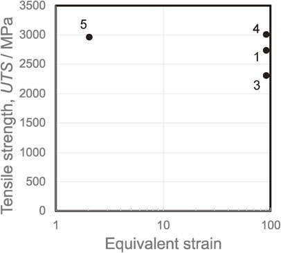
Figure 8 shows the effect of equivalent strain during the SPD process on the ultimate tensile strength. Here, the equivalent strain of around 2, in swaged specimen of alloy No. 6 and cold rolled specimen of alloy No. 8 in Table 1, can achieve as much as 2 GPa of UTS, and the further increase in equivalent strain gradually improves UTS up to 2.5 GPa. This gradual increase in UTS might be attributed to the strain induced transformation from γ to α′ which can be achieved only in the heavily strained specimens obtained by HPT up to 50 turns.
5. Conclusion
The recent researches on microstructure and mechanical properties in SPDed Fe–Ni–Co–Ti and Fe–Ni–Al–C alloys were overviewed. These alloys with lattice softening were processed with SPD to raise the strength up to ultrahigh strength level. Microstructural development during the SPD process consists of strain-induced transformation from γ to α′ and grain refinement and the sequence of the change in microstructure depends on the chemical compositions of the alloy. In the Fe–Ni–Co–Ti alloys, the phase stability of γ is not so high, and the transformation to α′ finishes in the early stage of SPD processing. On the other hand, the phase stability of γ is higher in the Fe–Ni–Al–C alloys, and the untransformed γ often remains after SPD processing. The SPDed Fe–Ni–Al–C alloys exhibit excellent ductility compared with the SPDed Fe–Ni–Co–Ti alloys, and this can be explained from the difference in the phase stability of γ. That is, the untransformed γ has a potent capability for plastic deformation where strain-induced transformation and deformation twinning can be expected to occur during mechanical tests after SPD processing. Simultaneous activation of these deformation mechanisms during plastic deformation would be a common feature in the lattice softened alloys, but the effects of alloying elements and phase stability on the deformation behavior have not been understood yet.
In addition, even in the Fe–Ni–Al–C alloys with higher stability of γ phase, total transformation to α′ can be achieved by significant amount of SPD, such as 50 turns of HPT. Unfortunately, the Fe–Ni–Al–C specimen with totally transformed α′ is brittle and does not show any ductility. This does not agree with the fact that the Fe–Ni–Co–Ti specimens with totally transformed α′ are not brittle and show about 10% of tensile elongation. This may be related to the capacity of local deformation. In the SPDed lattice softened alloys, capacity of strain hardening is small and strain localization easily occurs in the early stage of plastic deformation. In this situation, whether the material is ductile or not depends on the capacity of local plastic deformation. For examples, the giant fault in Gum Metal and the Lüders bands in Fe–Ni–Al–C alloys are considered to be evidences of such capacity of local deformation. However, similar evidence has not been found in Fe–Ni–Co–Ti and it has not been known what is the key to realize such conditions in the lattice softened alloys. Hence, the relation between microstructure and mechanical properties in these SPDed alloys are not fully understood and further researches will be required in future.
Acknowledgments
Most of the results referred in the present article have been performed in cooperation with Z. Horita and K. Edalati in Kyushu University, N. Tsuji and A. Shibata in Kyoto University, N. Nagasako, I. Miyazaki, K. Oh-ishi, T. Ohsuna, K. Horibuchi, N. Suzuki, A. Yamada and M. Sawamura in Toyota Central R&D Labs., Inc.
REFERENCES
- 1) S. Kuramoto, T. Furuta, N. Nagasako and Z. Horita: Appl. Phys. Lett. 95 (2009) 211901.
- 2) T. Furuta, S. Kuramoto, T. Osuna and Z. Horita: Proc. 2nd Int. Sym. Steel Sci. (ISSS 2009), ed. by K. Higashida and N. Tsuji, (The Japan Inst. Metals, 2010) pp. 151–154.
- 3) T. Furuta, S. Kuramoto, K. Horibuchi, T. Osuna and Z. Horita: J. Mater. Sci. 45 (2010) 4745–4753.
- 4) K. Edalati, S. Toh, T. Furuta, S. Kuramoto, M. Watanabe and Z. Horita: Scr. Mater. 67 (2012) 511–514.
- 5) T. Furuta, S. Kuramoto, T. Osuna, K. Oh-ishi and K. Horibuchi: Scr. Mater. 101 (2015) 87–90.
- 6) K. Edalati, T. Furuta, T. Daio, S. Kuramoto and Z. Horita: Mater. Res. Lett. 3 (2015) 197–202.
- 7) Y. Ma, M. Yang, P. Jiang, F. Yuan and X. Wu: Sci. Rep. 7 (2017) 15619.
- 8) I. Miyazaki, T. Furuta, K. Oh-ishi, T. Nakagaki, S. Kuramoto, A. Shibata and N. Tsuji: Mater. Sci. Eng. A 721 (2018) 74–80.
- 9) T. Furuta, I. Miyazaki, K. Oh-ishi, S. Kuramoto, A. Shibata and N. Tsuji: Mater. Des. 153 (2018) 166–176.
- 10) T. Saito et al. Science 300 (2003) 464–467.
- 11) S. Kuramoto, T. Furuta, J.H. Hwang, K. Nishino and T. Saito: Metall. Mater. Trans. A 37 (2006) 657–662.
- 12) T. Furuta, S. Kuramoto, J.W. Morris, Jr., N. Nagasako, E. Withey and D.C. Chrzan: Scr. Mater. 68 (2013) 767–772.
- 13) M. Hara, Y. Shimizu, T. Yano, N. Takesue, T. Furuta and S. Kuramoto: Int. J. Mater. Res. 100 (2009) 345–348.
- 14) A.G. Every and A.K. McCurdy: Landolt-Börnstein, New Series, Group III, Vol. 29, (Springer, Berlin, 1992) pp. 29–30.
- 15) S. Kuramoto, N. Nagasako, T. Furuta and Z. Horita: J. Alloys Compd. 577 Suppl. 1 (2013) S147–S150.
- 16) E. Cesari, V.A. Chernenko, V.V. Kokorin, J. Pons and C. Segui: Scr. Mater. 40 (1999) 341–345.
- 17) S. Muneki, Y. Kawabe and J. Takahashi: Trans. Iron Steel Inst. Jpn. 69 (1983) 983–989.
- 18) J.R. Mihalisin and C.G. Bieber: JOM 18 (1966) 1033–1036.
- 19) I. Ochiai, S. Nishida, H. Ohba and A. Kawana: Trans. ISIJ 79 (1993) 1101–1107.
- 20) Y. Oki, N. Ibaraki, K. Ochiai, T. Minamida and K. Maki: Kobe Steel Engineering Report 50 (2000) 37–40.
- 21) S. Kajiwara, T. Kikuchi and N. Sakuma: Proc. of ICOMAT (ICOMAT-86), (1986) pp. 991–996.
- 22) R. Pippan, S. Scheriau, A. Taylor, M. Hafok, A. Hohenwarter and A. Bachmaier: Ann. Rev. Mater. Res. 40 (2010) 319–343.
- 23) M. Kawasaki, H.J. Lee, B. Ahn, A.P. Zhilyaev and T.G. Langdon: J. Mater. Res. 3 (2014) 311–318.
- 24) G. Frommeyer, U. Brüx and P. Neumann: ISIJ Int. 43 (2003) 438–446.
- 25) D. Raabe, D. Pong, O. Dmitrieva and B. Sander: Adv. Eng. Mater. 11 (2009) 547–555.
- 26) I. Gutierrez-Urrutia and D. Raabe: Scr. Mater. 68 (2013) 343–347.
- 27) T. Furuta: Proc. of GSAM (GSAM2015), ed. by K. Edalati, Y. Ikoma and Z. Horita, (2015) pp. 28–30.