Abstract
Microstructural characterization of martensite with long period stacking order (LPSO) structure in a Hf–Co–Pd alloy was investigated by transmission electron microscopy (TEM) and high-angle annular dark-field scanning transmission electron microscopy (HAADF-STEM). LPSO structure with six stacking sequences; 6O (orthorhombic) (Space group: Immm), were newly discovered. Based on the electron diffraction experiments, the lattice parameters of LPSO phase were estimated to be a = 0.33 nm, b = 0.45 nm and c = 1.53 nm. The formation mechanism of martensite with LPSO structure and the crystallographic orientation relationship between parent B2 phase and 6O martensite are also discussed.
1. Introduction
Many types of martensitic phase with LPSO structure have been so far reported, such as, 18R in Cu–Al,1) Cu–Au–Zn,2) Cu–Sn3) and Cu–Zn4) alloys, 7R (14M) in Ni–Al5) alloy, 10M in Ni–Mn–Ga6) alloy, 4H in Ti–Ni–Cu7) alloy, 18R in Ti–Pd8) and Ti–Pt9) alloys. It is well known that the crystal structure and the number of stacking planes of LPSO phase depends on the electron/atom (e/a) ratio and/or the martensitic transformation points. For example, the martensitic transformation temperatures in the Ti–Pd–Fe alloys decrease with increasing the substituted amounts of Fe, that is, with decreasing the e/a ratio, and the crystal structure of those martensite changes from 2H(B19) to 9R, incommensurate and then 4H.10) Ni–Al–Mn alloys also have 14M, 12M and 10M structures according to decreasing the e/a ratio, leading to the decrease of the martensitic transformation temperatures.11)
Recently, we have newly discovered the LPSO structure with a period of six layers in Zr–Co–Pd alloy.12) Therefore, it is expected that Hf-based alloy consisting of the same group of Ti and Zr elements described above should have the LPSO structure. However, as far as we know, few studies have reported on martensitic transformation itself in Hf-based alloy, thus much less research on the martensite with LPSO structure.
The purpose of the present study is to investigate the existence and crystallography of martensite with LPSO structure in the Hf–Co–Pd alloy by TEM and HAADF-STEM. Based on these observations, the formation mechanism of such LPSO structure is also discussed.
2. Experimental Procedure
A Hf–30.0 at% Co–20.0 at% Pd alloy was prepared from 99.9% Hf, 99.9% Co, and 99.9% Pd (mass%) by arc melting in an argon atmosphere. The ingot was solution-treated in an argon atmosphere at 1273 K for 3.6 ks and then quenched into an ice water. Differential scanning calorimetry (DSC) measurements were performed with a calorimeter (DSC-60, Shimadzu) on a cooling and heating rate of 0.17 K/s. In order to mainly analyze the thermally induced martensites in this study, the solution-treated samples were immersed in the liquid nitrogen once. Subsequently, disk-shaped specimens with 3 mm in diameter for TEM studies were spark-cut from those samples and ground to thickness of 80 µm. The specimens were then dimpled with GATAN Model 656 dimple grinder and Ar ion milled with GATAN Model 691 PIPS system. TEM observations were performed using a JEM-2000FX microscope at an accelerating voltage of 200 kV. HAADF-STEM observations were performed using a JEM-ARM200F microscope (Cs-corrected 200 kV STEM, JEOL). The beam diameter of the electron probe was 0.1 nm and the current was approximately 20 pA. For obtaining the HAADF-STEM images, the annular detector was set to collect electrons scattered at angles between 90 and 170 mrad.
3. Results and Discussion
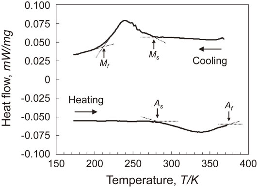
Figure 1 shows the DSC curves for a solution-treated specimen. During cooling an exothermic peak corresponding to the martensitic transformation is existed. The martensitic transformation start (Ms) and finish (Mf) temperature are estimated to be 275.5 K and 211.8 K, respectively, based on the point of intersections of baseline and tangent. Correspondingly, an endothermic peak during heating is observed, providing that the reverse transformation start (As) and finish (Af) temperatures are determined to be 281.1 K and 373.0 K, respectively. Compared with the transformation temperatures of equiatomic HfPd alloy,13) those temperatures decrease by the substitution of Co for Pd.
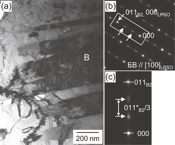
A typical bright-field image shown in Fig. 2(a) indicates some martensitic variants with plate-like morphology in B2 matrix. Figure 2(b) is the selected area diffraction pattern taken from the area B in Fig. 2(a). This diffraction pattern cannot be indexed as B33 structure, as expected from the martensites of equiatomic HfPd alloy13) and Zr–30.0 at% Co–20.0 at% Pd alloy14) with the same e/a ratio of 6.7 as the present Hf–30.0 at% Co–20.0 at% Pd specimen. It is noted that extra spots are detected between transmitted beam and the fundamental reflection of (011)B2 plane corresponding to the parent B2 phase, as indicated by the arrows in Fig. 2(b). Those extra spots are located in the one-third positions of the spot derived from (011)B2 plane in the enlarged pattern shown in Fig. 2(c). It is apparent that the extra spots are derived from LPSO structure.
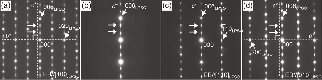
In order to clarify the crystallographic features of this LPSO structure, a series of selected area diffraction patterns were taken from a single martensite variant by tilting experiments. According to the crystallography of martensite, the LPSO structure is attributable to the periodical stacking change of (110)B2 planes upon martensitic transformation. Therefore, the position of extra spots along 110*B2 corresponds to the stacking sequence of the basal plane of the LPSO structure. Judging from both electron diffraction patterns and HAADF-STEM observations described below, we can index as (006)LPSO and (020)LPSO reflections by referring to 6O structure in Zr–38.0 at% Co–12.0 at% Pd alloy,12) as shown in Fig. 3(a). This provides that Fig. 3(a) is the electron diffraction pattern taken along the [100]LPSO direction of the LPSO structure. c*-axis is perpendicular to the b*-axis, as apparently from the dotted lines in Fig. 3(a), and the spot distribution on both side of the c*-axis is symmetric. Furthermore, the intensity of the 00l reflections indicated by two arrows in Fig. 3(b) does not decrease on tilting around the c*-axis from the [100]LPSO zone axis, proving that those 00l reflections are not due to multiple diffraction. Subsequently, by tilting about 54 degree around c*-axis from [100]LPSO zone axis of Fig. 3(a), the electron diffraction pattern of Fig. 3(c) is obtained. We can index $\{ \bar{1}10\} _{\text{LPSO}}$ reflection on both side of the c*-axis and it is apparent that Fig. 3(c) is the diffraction pattern taken from the [110]LPSO zone axis. With titling further 36 degree from [110]LPSO zone axis of Fig. 3(c), the diffraction pattern of Fig. 3(d) taken from the [010]LPSO zone axis is appeared. As indicated by the dotted line in Fig. 3(d), c*-axis is perpendicular to a*-axis, and the spot distribution on both side of the c*-axis is symmetric. From these tilting experiments, LPSO structure in the present Hf–Co–Pd alloy has an orthorhombic structure.
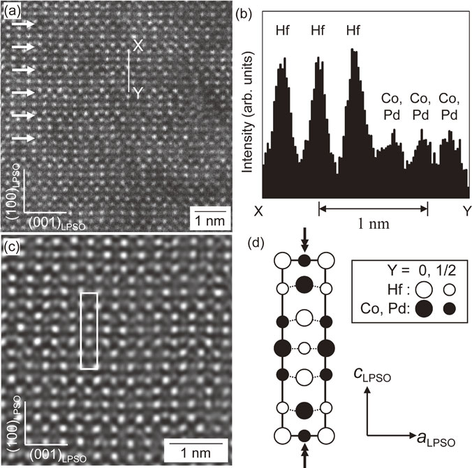
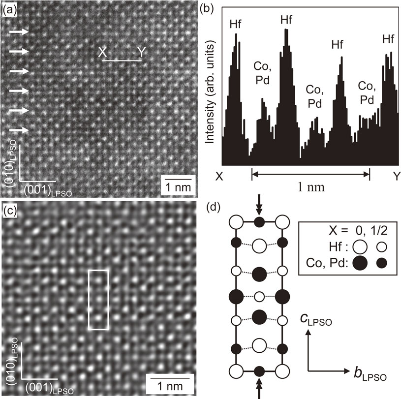
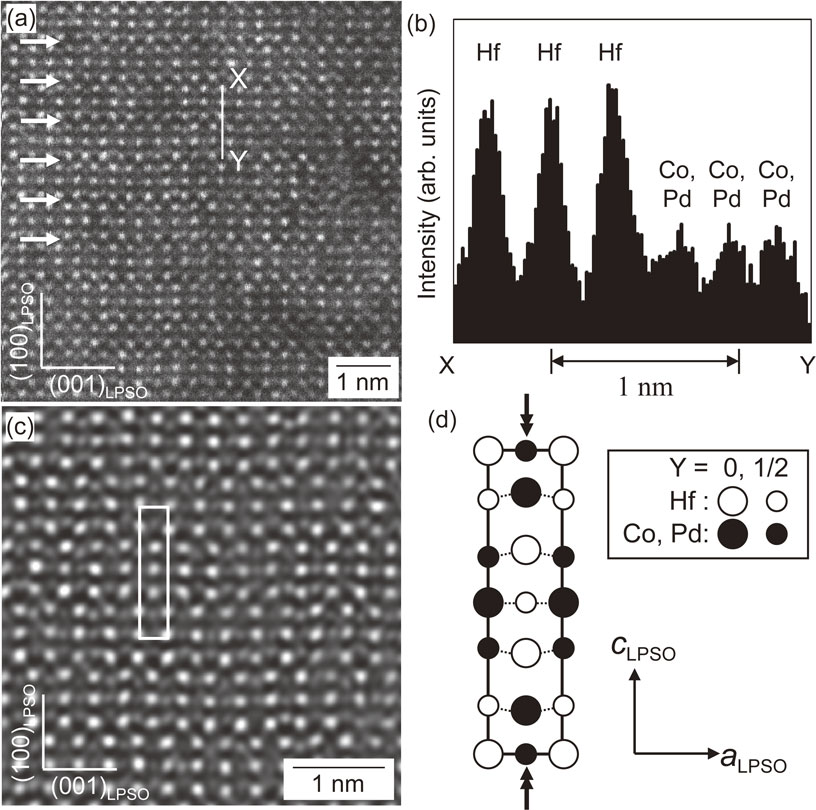
HAADF-STEM observations using Z contrast were carried out to locate in the atomic columns of LPSO structure. Figure 4(a) shows the HAADF-STEM image of the LPSO structure taken along the [100]LPSO direction. Each Hf and Co and/or Pd atomic column are followed by the same atomic column along the [100]LPSO direction on the basis of the formation mechanism of LPSO structure transformed from the parent B2 phase mentioned below. LPSO structure consists of a period of three layers, as apparently from the arrows in Fig. 4(a). Figure 4(b) shows the image intensity profile taken along the white line X-Y in Fig. 4(a). Co–Pd binary phase diagram supports that Co and Pd forms a complete solid-solution. The substituted amount of Pd for Co is also limited to 20 at% in the present alloy, suggesting that the Pd atoms are considered to be existed in Co sites. Therefore, based on the nature of Z-contrast, the higher-intensity profile shows Hf (Z = 72) columns. On the other hand, the lower-intensity one indicates Co (Z = 27) and/or Pd (Z = 46) columns. Thus, the bright and semi-dark spots in Fig. 4(a) correspond to the Hf and Co(Pd) atomic columns, respectively. The Fourier filter-processed image of the LPSO structure is shown in Fig. 4(c), and the atomic arrangements in the white-framed area of Fig. 4(c) are schematically illustrated in Fig. 4(d). The open and solid circles indicate the Hf and Co(Pd) atomic columns, respectively. With respect to the large and small circles in Fig. 4(d), it will be described later. Judging from the atomic species and the atomic displacement along the c-axis on the (020)LPSO plane indicated by double arrows in Fig. 4(d), it is apparent that LPSO structure consists of six stacking sequences. Figure 5(a) shows the HAADF-STEM image of the LPSO structure along the [010]LPSO zone axis. Figure 5(b) shows the image intensity profile taken along the white line X-Y in Fig. 5(a). The bright and semi-dark spots in Fig. 5(a) correspond to the Hf and Co(Pd) atomic columns, respectively, according to the ratio of intensity due to the nature of the Z contrast, as found in Fig. 5(b). The Fourier filter-processed image of the LPSO structure is presented in Fig. 5(c), and the atomic arrangements in the white-framed area of Fig. 5(c) are schematically illustrated in Fig. 5(d). The open and solid circles indicate the Hf and Co(Pd) atomic columns, respectively. As well as the atomic arrangements in Fig. 4(d), this LPSO structure is composed of six stacking sequences on the basis of atomic species and atomic positions on the (200)LPSO plane indicated by double arrows in Fig. 5(d). Considering HAADF-STEM observations along both [100]LPSO and [010]LPSO zone axes, each large and small circles in Fig. 4(d) and Fig. 5(d) correspond to the atoms on two different (h00)LPSO and (0k0)LPSO planes, respectively, leading to the determination of description and space group of the LPSO structure.
Here, based on the Otsuka’s notation,15) LPSO is represented by combination of both the number of stacking layers and Bravais lattice. Therefore, this newly discovered LPSO in Hf–Co–Pd alloy has the orthorhombic structure with six stacking sequences, proposing as “6O” structure, whose lattice parameter is estimated to be a = 0.33 nm, b = 0.45 nm, c = 1.53 nm from electron diffraction experiments. According to this notation, all the electron diffraction patterns can be indexed consistently. Subsequently, on the basis of the extinction rule of orthorhombic system judged from electron diffraction experiments along various directions, as shown in Fig. 3, LPSO structure has a possibility of the four space groups, I222, I212121, Imm2 and Immm, according to the international tables for crystallography. Atomic arrangements of Fig. 4(d) and Fig. 5(d) mean that this type of centering of the LPSO structure is given as the symbol I, and each of the principal axes [100]LPSO, [010]LPSO and [001]LPSO has mirror planes. Consequently, the space group of the LPSO structure is determined to be Immm on the basis of both the extinction rule and symmetry. This study must be the first report on LPSO structure with six stacking sequences in Hf-based alloy.
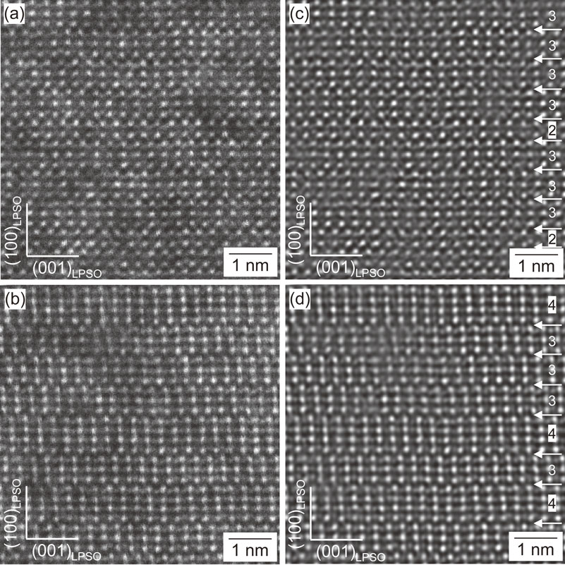
Next, we discuss the formation mechanism of the LPSO structure. Figures 6(a) and (b) show the HAADF-STEM image of the LPSO in another area taken along the [010]LPSO direction, and Fig. 6(c) and (d) show the Fourier filter-processed images of (a) and (b), respectively. It has been reported that B33 martensite transformed from the parent B2 phase is formed by shear and shuffle with successive atomic shifts along two opposite directions by +1/2[100]B2 and −1/2[100]B2 on pairs of {011}B2 planes.16,17) Referred to the formation mechanism of such B33 structure, horizontal direction of Fig. 6(c), that is, [100]LPSO direction indicates the shearing and shuffling direction during martensitic transformation from the parent B2 phase to LPSO structure. Vertical direction of Fig. 6(c), that is, [001]LPSO direction also shows the stacking of shear planes. It is apparent that Fig. 6(c) consists of mainly the periods of three layers, and a little of period of two layers is also observed, as indicated by the arrows. Therefore, each LPSO and B33 structure having a period of three and two layers, respectively, should coexist in the region of Fig. 6(a). This means that the shearing and shuffling direction to form LPSO and/or B33 structure from parent B2 phase during martensitic transformation is the same, but only the number of staking planes is differed. Consequently, the present LPSO structure with six stacking sequences is considered to be formed by shearing every third (011)B2 plane along two opposite directions with +1/2[100]B2 and −1/2[100]B2. Furthermore, periods of four layers in addition to three ones are observed in Fig. 6(d). It is also expected that the LPSO structure with a period of four layers should be formed depending on alloy compositions. These results support that the stacking fault energy on the basal plane decreases with increasing the substituted amounts of Co for Pd in equiatomic HfPd alloy, leading to the formation of LPSO structure with various periods.
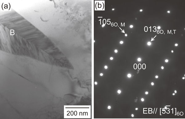
We discuss the crystallographic orientation relationship between B2 parent phase and 6O martensite. Figures 7(a) and (b) shows the bright field image in the region coexisted with both phases and the electron diffraction pattern taken from the area marked as B in Fig. 7(a), respectively. The orientation relationship between parent B2 phase and 6O martensite is determined to be (010)B2 // (013)6O, (011)B2 // (001)6O and [100]B2 // [100]6O, as apparently from Fig. 7(b). Figures 8(a) and (b) shows the bright field image of a pair of martensitic variants with lenticular morphology in B2 matrix and the electron diffraction pattern taken from the area marked as B in (a), respectively. The electron diffraction pattern in Fig. 8(b) is composed of two sets of reflections from the $[5\bar{3}1]_{\text{6O}}$ zone axis that is in mirror symmetry with respect to the (013)6O plane, which is parallel to the interface of a pair of two variants. This fact indicates that those variant boundaries are in (013)6O twin relations. In addition, many striations are existed within variants in accord with a deviation of period of three layers in LPSO structure on the basis of HAADF-STEM observations in Fig. 6. It has been widely recognized that the lattice invariant shear (LIS) of martensite with LPSO structure, such as 18R and 7R, is a stacking fault on the (001)LPSO basal plane.18) Therefore, (013)6O twin mentioned above should be variant accommodation twin19–21) to minimize the shear strain between martensitic variants. Further crystallographic studies such as self-accommodation structure should be required in future.

4. Conclusions
The crystallography and formation mechanism of maternsite with long period stacking order structure in Hf–Co–Pd alloy were investigated by TEM and HAADF-DTEM observations. The obtained results can be summarized as follows.
-
(1)
LPSO structure with six stacking sequences; 6O (Space group: Immm), were newly discovered. Based on the electron diffraction experiments, the lattice parameters of LPSO phase were estimated to be a = 0.33 nm, b = 0.45 nm and c = 1.53 nm.
-
(2)
The 6O structure is formed by shearing and shuffling along two opposite directions with ±1/2[100]B2 on every third (011)B2 plane during martensitic transformation from parent B2 phase.
-
(3)
The crystallographic orientation relationship between parent B2 phase and 6O martensite is determined to be (010)B2 // (013)6O, (011)B2 // (001)6O and [100]B2 // [100]6O. Furthermore, (001)6O stacking faults were existed within martensitic variants, and (013)6O twin should be variant accommodation twin to minimize the shear strain between martensitic variants.
REFERENCES
- 1) Z. Nishiyama, J. Kakinoki and S. Kajiwara: J. Phys. Soc. Jpn. 20 (1965) 1192–1211.
- 2) T. Tadaki, H. Okazaki, Y. Nakata and K. Shimizu: Mater. Trans. JIM 31 (1990) 941–947.
- 3) K. Shimizu, H. Sakamoto and K. Otsuka: Trans. JIM 16 (1975) 581–590.
- 4) T. Tadaki, M. Tokoro and K. Shimizu: Trans. JIM 16 (1975) 285–296.
- 5) K. Enami, A. Nagasawa and S. Nenno: Scr. Metall. 12 (1978) 223–226.
- 6) J. Pons, V. Chernenko, R. Santamarta and E. Cesari: Acta Mater. 48 (2000) 3027–3038.
- 7) T. Tadaki, K. Shimizu and C.M. Wayman: Mater. Trans. JIM 32 (1991) 43–47.
- 8) M. Matsuda, S. Yano and M. Nishida: Mater. Trans. 52 (2011) 2016–2021.
- 9) M. Nishida, M. Matsuda, Y. Yasumoto, S. Yano, Y. Yamabe-Mitarai and T. Hara: Mater. Sci. Technol. 24 (2008) 884–889.
- 10) M. Todai, T. Fukuda and T. Kakeshita: Mater. Trans. 51 (2010) 906–910.
- 11) S. Morito and K. Otsuka: Mater. Sci. Eng. A 208 (1996) 47–55.
- 12) M. Matsuda, F. Tanaka, S. Tsurekawa, K. Takashima, M. Mitsuhara and M. Nishida: Philos. Mag. Lett. 95 (2015) 21–29.
- 13) S. Hisada, M. Matsuda, K. Takashima and Y. Yamabe-Mitarai: J. Solid State Chem. 258 (2018) 712–717.
- 14) M. Matsuda, T. Nishimoto, Y. Morizono, S. Tsurekawa and M. Nishida: Intermetallics 19 (2011) 894–899.
- 15) K. Otsuka, T. Ohba, M. Tokonami and C.M. Wayman: Scr. Metall. Mater. 29 (1993) 1359–1364.
- 16) A. François and P. Veyssière: Intermetallics 2 (1994) 9–22.
- 17) J.R. Morris, Y. Ye, M. Krcmar and C.L. Fu: MRS Proc. 980 (2006) 0980-II06-10.
- 18) Z. Nishiyama: Martensitic Transformation, (Academic Press, New York, 1978).
- 19) H. Tas, L. Delaey and A. Deruyttere: Metall. Trans. 4 (1973) 2833–2840.
- 20) T.A. Schroeder and C.M. Wayman: Acta Metall. 25 (1977) 1375–1391.
- 21) T. Saburi and C.M. Wayman: Acta Metall. 27 (1979) 979–995.