Abstract
To reduce the processing time for in-line carburizing, we performed ultra-rapid carburizing and quenching using induction heating. Conventional gas carburizing and vacuum carburizing (low-pressure carburizing) are treated at 1203–1323 K, which is lower than the eutectic temperature. In contrast, in this study, the carburizing temperature of 1523 K was higher than the eutectic temperature for speeding up this process. The SCM420 sample was rapidly heated to the treatment temperature by induction heating. CH4 and N2 were mixed and treated at atmospheric pressure at 5 vol% CH4 and 10 vol% CH4. For ultra-rapid carburizing, the total carburizing depth was proportional to the square root of the carburizing time, following the parabolic law, regardless of the CH4 concentration. We obtained that the amount of carbon penetrating the steel from the atmosphere was proportional to the carburizing time. In other words, the carbon penetration rate was approximately constant during the carburizing process. The processing time for the ultra-rapid carburizing and quenching at 1523 K in this study was only 5% of that for the conventional gas carburizing at 1203 K.
This Paper was Originally Published in Japanese in J. Jpn. Soc. Heat Treatment 61 (2021) 183–190.
1. Introduction
Heat treatment is an indispensable method for imparting the required strength to mechanical parts made of steel used in automobiles, railways, industrial machinery, etc., depending on the environment in which it is used. Among types of heat treatments, carburizing and quenching impart advantageous mechanical properties, such as wear resistance and fatigue strength, and are therefore applied to many components, such as power transmission parts, as a typical surface modification treatment.1–4) For carburizing, gas carburizing is the most widely used method because it allows for stable heat treatment quality and mass production.
Gas carburizing requires a long-duration treatment at high temperatures between 1203 K and 1223 K in a controlled atmosphere to impart the required strength to the parts.5,6) The processed products are appropriately stacked and placed in a basket on a tray for transport and then subjected to extensive processing to achieve stable quality after heat treatment. The atmosphere required for carburizing the steel is typically introduced into the furnace at a constant CO/CO2 ratio using an endothermic gas generator with a device known as a metamorphic furnace. However, since steel cannot be carburized in this atmosphere, the carbon potential is adjusted by adding an enriched gas, such as butane, to reduce the partial pressure of CO2. The steel being case-hardened is placed in this adjusted atmosphere so that carbon penetrates the surface of the steel material, mainly through the Boudouard reaction.
Recently, vacuum (low-pressure) carburizing has attracted attention as a method with greater merit than gas carburization because it does not require an endothermic gas generator. Vacuum carburizing involves directly introducing a hydrocarbon-based gas into a low-pressure furnace, a gas decomposition reaction, and steel penetration by carbon.7) Treating steel at low-pressure reduces the amount of source gas material required for carburization. Moreover, internal oxidation is not a concern because O2 is absent from the carburizing atmosphere. Additionally, applying a vacuum furnace set-up suppresses heat dissipation from the furnace wall, which facilitates high-temperature treatment with a reduced treatment time.8)
Various studies have described the mechanism of vacuum carburizing, which has led to an increase in mass production and the establishment of quality control technologies, such as the saturation value adjustment method,9) and the study and proposal of methods related to carburizing calculations.10–12) Previous studies have reported on its merits13) and proposed further technological innovation, such as the utilization of alloy-saving steel formed by double-heat treatment using vacuum carburizing and induction hardening.14,15)
On the other hand, various machining processes, such as turning and grinding, are performed before and after the carburizing process. Machining is a production method in which each item is processed individually. For this reason, a production form with a large inprocess inventory is required for synchronous production with the carburizing and quenching processes, mainly based on lot processing. This is an obstacle to improving productivity, as it involves a greater need for logistics, storage space, and inventory management.
The recent intensification in global environmental conservation, energy-saving, and CO2 reduction activities has coincided with increased interest in sustainable development goals, and it is becoming increasingly important to take measures toward carbon neutrality.16) The equipment and processes used in heat treatment consume a significant amount of electricity, gas, and oil; therefore, the pressure to address environmental impacts is high, and demand for technological development to improve efficiency and reform production processes is increasing.1) Many processes involving carburization are awaiting the development of technology that can enable inline carburizing with the goal of improving productivity,13) and demand for short-duration treatments is increasing.
Carburizing requires long treatments at a typical carburizing temperature of 1203 K.17) Increasing the treatment temperature is the most effective method for reducing the processing time of a carbon diffusion process such as carburizing.4,18–23) In gas carburizing, high-temperature treatment is considered efficient at approximately 1223 K–1253 K.24) Increasing the carburizing temperature to 1303 K–1323 K was reported to reduce the needed time by approximately 60% because high-temperature treatment is possible for vacuum carburizing.25,26) Other reported results at 1373 K27) demonstrate that high-temperature treatment is necessary to improve productivity.28)
However, high-temperature treatment using conventional gas or vacuum carburizing is limited in practice by the structure and construction of furnaces, as well as their ability to withstand high temperatures.24) Furthermore, indirect heating methods using electric resistance or gas have previously been the primary methods for heating to a high processing temperature. Therefore, more time is required to increase the component’s temperature to the target processing temperature, which is a disadvantage for achieving short processing times.
Based on the findings above, it is necessary to set-up a temperature treatment that enables a high-speed temperature ramp in order to pursue inline carburizing for further acceleration of carburizing. Therefore, an ultra-rapid carburizing process using induction heating that enables rapid heating rates for inline carburizing was devised.29,30) This carburizing treatment is performed at 1473 K–1573 K, which is higher than conventional carburizing treatment temperatures and is also above the eutectic temperature (1420 K) for high-speed carburizing. In the treatment temperature range used for gas or vacuum carburizing, Fe3C precipitates as the carbon concentration in the steel increases. In contrast, ultra-rapid carburizing uses a treatment temperature range in which the system crosses the solidus line as carbon concentrations in the steel increase and melting begins. If melting occurs, the product’s shape is impaired and thus cannot be used as a machine part. Therefore, predicting and controlling carburizing treatment conditions is important to avoid melting while performing treatments that satisfy the appropriate heat treatment quality. Additionally, it is essential to elucidate the carburizing mechanism for predicting heat treatment conditions. However, in various carburizing methods, the behavior of carbon penetrating from the atmosphere differs depending on the method.5)
In order for ultra-rapid carburizing to be used as an industrially significant technology in the future, it will be necessary to optimize it by examining the most efficient treatment conditions. Understanding the carbon penetration characteristics of steel materials in different treatment environments during ultra-rapid carburizing is required for this purpose. However, no systematic studies on carburizing mechanisms at temperatures above 1420 K have yet been conducted. Thus, this study investigated the effect of the carburizing atmosphere on the carbon penetration rate in ultra-rapid carburizing to improve understanding of this basic phenomenon.
2. Experimental Procedure
2.1 Test materials
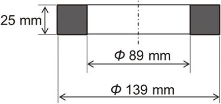
The material used in the experiment was SCM420, a case-hardening steel mostly used in carburizing and quenching. This material was chosen assuming the application for commercial use. Table 1 lists the chemical compositions of the material. As shown in Fig. 1, the sample was machined into a ring shape with an outer diameter of 139 mm, an inner diameter of 89 mm, a width of 25 mm, and finished surface roughness of Ra = 6.4 µm. The sample was degreased, washed with ethanol, and subjected to heat treatment.
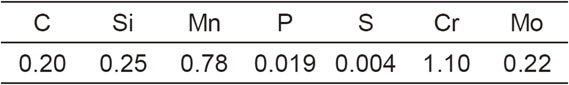
Table 1 Chemical composition of SCM420 (mass%).
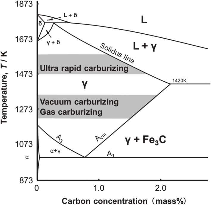
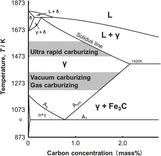
Figure 2 depicts the Fe–C equilibrium phase diagram and the temperature range for each carburizing method. Generally, carburizing temperatures range from 1203 K to 1253 K for gas carburizing and from 1253 K to 1323 K for vacuum carburizing. As the concentration of dissolved carbon during carburization increases, it reaches the Acm line and Fe3C precipitates. In contrast, the treatment temperature for ultra-rapid carburizing is 1473–1573 K, which is higher than the eutectic temperature and is used to reduce processing time. Therefore, when the carbon concentration in the solid solution increases due to carburizing, it crosses the solidus line, and melting occurs.
In this experiment, ultra-rapid carburizing and quenching equipment (JTEKT THERMO SYSTEMS CORPORATION) capable of high-temperature treatment was used. A schematic of the set-up is shown in Fig. 3. The equipment consists of two modules: a heated carburizing module and a quenching module, which are located on the right and left sides, respectively, and can be rapidly heated by induction heating, support carburizing at high temperatures, and perform quenching.

Figure 4 shows the details of the carburizing module. An induction coil for heating the sample was placed in the heating chamber, and the sample was positioned on a rotating table made of carbon at the center of the coil. Prior to treatment, the air in the chamber was evacuated using a rotary pump, and the sample was heated to the target temperature by induction heating while maintaining a low-pressure state without vacuum discharge. During this process, the induction heating frequency was set to 1 kHz. The sample temperature was adjusted to match the target temperature by controlling the induced heating output and was monitored using a radiation thermometer. The emissivity of the radiation thermometer was adjusted according to the temperature of a thermocouple attached to the sample. When the sample temperature reached the target temperature, a mixture of CH4 and N2 gas was introduced while exhausting the gas during carburizing, followed by quenching.
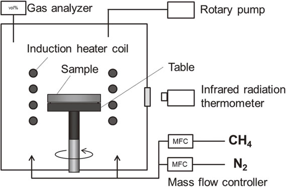
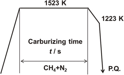
Figure 5 shows the heat treatment pattern, and Table 2 lists the heat treatment conditions. The carburizing temperature was fixed at 1523 K, and the carburizing time was in the range of 180–1440 s. The carburization atmosphere was a gas mixture of CH4 and N2, with the relative concentration of CH4 set at either 5 vol% or 10 vol%, and the treatment was performed under atmospheric pressure. After maintaining the carburizing temperature, the system was allowed to cool to 1223 K and then quenched with a 293-K water-soluble polymer solution (hereafter referred to as P.Q.).

Table 2 Carburizing conditions.
Gas carburizing and quenching often employ carburizing and diffusion steps to modify the carbon concentration profile. In vacuum carburizing, the desired carbon concentration profile is obtained by repeating the carburizing and diffusion steps based on the saturation value adjustment method;9) however, no diffusion step was performed in this experiment. In ultra-rapid carburizing, it is possible to carburize for a short time using high-temperature treatment, although the mechanical strength decreases32–35) due to coarsening of the austenite grains.22,31) In recent years, there has been progress in research on the pinning effect of Nb and Ti additions to Al, which is conventionally used for high-temperature treatment,28,36) and work on the prevention of grain coarsening at 1423 K has also been reported.6) Because this study is focused on finding applications for materials that are in general supply, measures to prevent coarsening of crystal grains cannot be taken for the SCM420 used in the experiment. In that case, it would be necessary to miniaturize the crystal grains by requenching, which was not performed in this experiment, the main purpose of which is to investigate the carbon penetration characteristics during carburizing.
2.3 Analytical evaluation
The following analyses were performed on the samples obtained from the experiments. To measure the amount of carbon that penetrated the steel surface during carburizing, the mass of the sample before and after heat treatment was measured using an A & D electronic balance (model: GX6100). The carbon penetration amount M (mol m−2) and carbon flux F (mol m−2 s−1) were obtained from the mass change and the surface area of the sample.7,27)
The surface’s condition after heat treatment was confirmed by observing its appearance and measuring the surface morphology using an instrument for determining surface roughness (model: SE300, manufactured by Kosaka Laboratory Co., Ltd). To investigate the resulting properties from heat treatment under each condition, the carbon concentration at the sample surface was measured using glow discharge–optical emission spectroscopy (GD–OES) and was analyzed using a Marcus-type high-frequency glow discharge optical emission surface analyzer (model: GD-Profiler2, manufactured by HORIBA, Ltd). Furthermore, a hardness test was performed on a cross-section of the sample using a micro-Vickers hardness tester (model: HM-200, manufactured by Mitutoyo Corp.). Lastly, microstructural observations were conducted using a digital microscope (model: DSX510; manufactured by Olympus Corp.).
3. Results and Discussions
3.1 Effect on the total carburizing depth
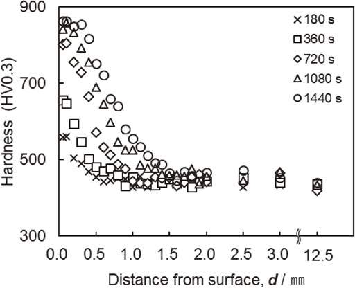
A hardness test was performed on the cross-section at the center of the width of the outer diameter of the sample. Figure 6 depicts the results of the obtained hardness profiles. From the hardness profiles under a condition of 5% CH4 shown in Fig. 6, it can be seen that the carburized layer grows with increasing carburizing time.
In general, carburizing is established by carbon diffusion, and the total carburizing depth can be calculated using Harris’s empirical formula,37) expressed by eq. (1), regardless of the carburizing method.38) Here, D is the total carburizing depth (in), t is the carburizing time (h), and T is the carburizing temperature (°F +460).
| \begin{equation}
\boldsymbol{D} = \{ 31.6/10^{(6700/\boldsymbol{T})}\} \cdot \sqrt{\boldsymbol{t}}
\end{equation}
| (1) |
When the distance,
D, in
eq. (1), is converted to (mm), and the units of time,
t, and temperature,
T, are converted to (s) and (K), respectively,
eq. (2), is obtained.
| \begin{equation}
\boldsymbol{D} = \{ 13.4/10^{(\frac{6700}{1.8\boldsymbol{T} + 0.3})}\} \cdot \sqrt{\boldsymbol{t}}
\end{equation}
| (2) |
In the cross-sectional hardness profile shown in Fig. 6, the position of the hardness, which is 30 HV higher than the substrate hardness in the center of the sample, where the distance from the surface is 12.5 mm, is defined as the total carburizing depth. Figure 7 shows the relationship between the carburizing depth, D, and carburizing time, t. This figure also shows the calculated value of the total carburizing depth obtained using eq. (2). The measured data demonstrate that the total carburizing depth was proportional to the square root of the carburizing time at all CH4 concentrations. In addition, because the trend in the data was similar to that of the calculated value, the total carburizing depth had the same relationship as in eq. (2), regardless of the CH4 gas concentration, even in ultra-rapid carburizing. Thus, Harris’s empirical formula37) holds even at 1523 K.
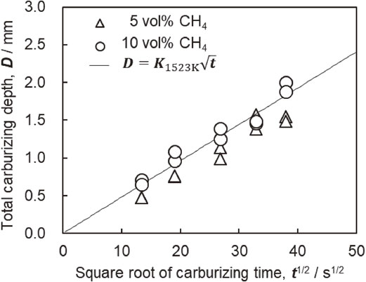
The time needed at 1203 K for conventional gas carburizing was calculated using eq. (2), and the effect of shortening the treatment time for ultra-rapid carburizing and quenching at 1523 K was confirmed using the total carburizing depth obtained under the treatment conditions shown in Table 2. For example, at a pressure of 1523 K-10% CH4-720 s, the carburizing time required to obtain the same carburizing depth at a treatment temperature of 1203 K was calculated to be 15840 s. The effect of reduced time on carburizing was confirmed using the combined experimental results obtained in this study at 1523 K. The findings confirmed that ultra-rapid carburizing and quenching at 1523 K had a processing time that was, on average, 5% of that at 1203 K, indicating that the processing time could be significantly reduced. Because the hardness profiles in other parts of the sample, such as the side and upper surfaces, were the same, the temperature in the sample was probably constant at all positions.
3.2 Effect on mass change
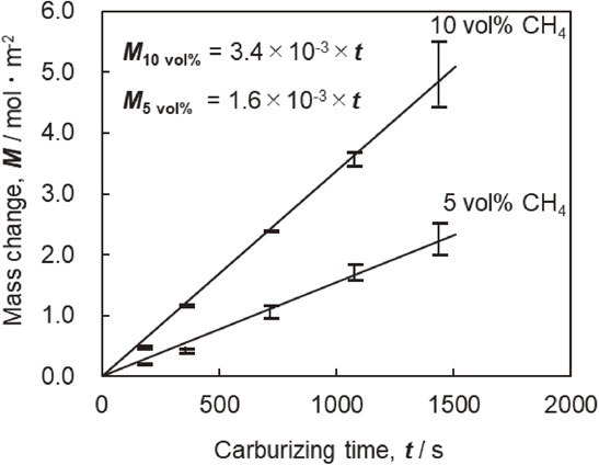
The amount of carbon that penetrated the sample surface was determined using the difference in mass before and after heat treatment. When evaluating the mass change, the possibility of soot deposition during carburizing and the influence of deposits due to P.Q were both considered; however, performing the degreasing step with ethanol before and after the process eliminated this possibility. Figure 8 shows the linear relationship between the change in the amount of carbon penetration and carburizing time depicted by a line through the origin, and it is clear that carbon penetrated the sample surface at a constant rate as carburizing time passed. The carbon penetration rate corresponds to the slope of the approximate line for each CH4 concentration in Fig. 8. These values are 1.6 × 10⁻³ mol m−2 s−1 for 5% CH4 and 3.4 × 10⁻³ mol m−2 s−1 for 10% CH4. By comparing these values, the carbon penetration rate was proportional to CH4 gas concentration, suggesting that the partial pressure of CH4 near the sample surface affects carburizing.7,39)
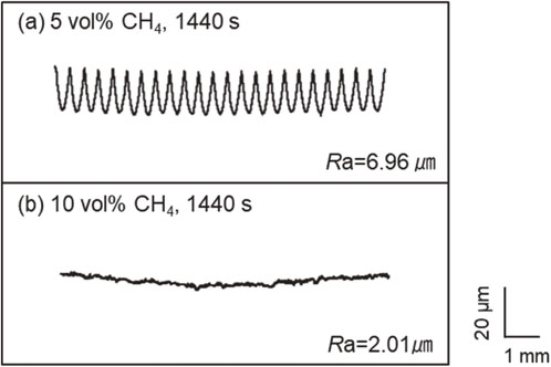
As a result of observing the appearance of the surfaces after heat treatment, the sample surfaces began to melt at carburizing times of 1080 s and 1440 s in 10% CH4. Figure 9 shows the appearance of the sample heated in 10% CH4 for 1440 s with the highest degree of melting, and the sample heated in 5% CH4 for 1440 s without melting, respectively, did not melt. The carburized sample in 10% CH4 melted evenly, particularly when the corners were already severely melted. This is assumed to be due to a shift in the carbon concentration from the solidus line to the low-concentration side, and the influence of the amount of carbon penetration per volume in the sample shape is more significant at the edges than on the smooth surface.40) The threshold carbon concentration at the solidus was reached relatively quickly, and partial abnormal overheating of the corners was attributed to the skin effect, which increases the eddy current density generated by induction heating on the surface and edges of the sample. Figure 10 shows the results of tests performed with a surface roughness meter to determine the sample surface character and confirm whether or not the sample melted. The surface roughness of the sample that was unmelted at 1440 s in 5% CH4 was Ra = 6.96 µm, and this surface state was maintained after processing. On the other hand, the surface roughness of the sample heated for 1440 s in 10% CH4 was Ra = 2.01 µm, and the surface was changed after processing. This is because the original unevenness generated by the machining process was smoothed out by melting.

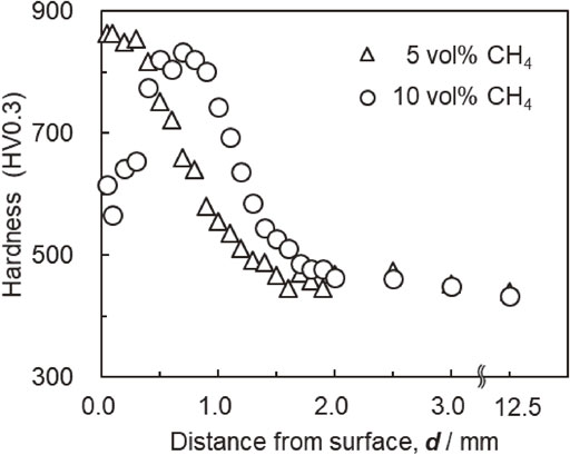
Afterward, the heat treatment properties of the sample were investigated. Figure 11 shows the microstructural observation results for a sample cross-section etched using nital corrosion, while Fig. 12 depicts the results of the hardness test and an excerpt of the applicable conditions from Fig. 6 and the hardness profile in 10% CH4. Additionally, martensite was uniformly observed near the surface of the unmelted sample after 1440 s in 5% CH4. The results of the cross-sectional hardness test shown in Fig. 12 indicate a hardness near the surface of approximately 850 HV. In contrast, as shown in Fig. 11, martensite and a large amount of retained austenite were observed in the microstructure near the surface of the melted sample cross-section. Based on the hardness test results in Fig. 12, a decrease in hardness was observed near the surface, which was considered to reflect the presence of the retained austenite.41) Therefore, it was presumed that the carbon concentration had increased at the surface of the melted sample. The higher carbon concentration on the sample surface was interpreted to be due to the high-temperature treatment at 1523 K, during which the solidus line shown in the Fe–C equilibrium diagram in Fig. 2 was reached, and part of the sample melted. Regarding the Fe–C equilibrium diagram, the relationship between the solidus carbon concentration, Cs, (mass%) and temperature, T, (K) is expressed by eq. (3).42)
| \begin{equation}
\boldsymbol{T} = 1528.4 - 177.9\times \boldsymbol{C}\mathbf{s}
\end{equation}
| (3) |

The calculated carbon concentration at the solidus for a carburizing temperature of 1523 K in this experiment based on eq. (3) is 1.56 mass%. Therefore, to confirm the change in surface carbon concentration of the sample with carburizing time, the carbon concentration on the sample surface was determined by GD–OES. Figure 13 shows the relationship between the surface carbon concentration and the carburizing time. The surface carbon concentration increased with increasing carburizing time in both 5% CH4 and 10% CH4 atmospheres, with melted samples in 10% CH4 having surface carbon concentrations of 1.07 mass% for 1080 s and 1.21 mass% for 1440 s. Although the results show that a carbon concentration of at least 1.07 mass% was reached at the solidus, the carbon concentration at the surface of the melted sample in this experiment was lower than that indicated by the calculation. The reason for this difference could be that after carburizing was completed during the set duration, the surface carbon concentration decreased due to carbon diffusion into the steel while it was being cooled before quenching. Alternatively, in terms of possible influences from alloying elements contained in the SCM420 material used for the sample in this experiment, the solidus line may have shifted to lower carbon concentrations due to the presence of ferrite-forming elements, such as Cr and Mo.

Thus, although there are complicating factors, surface carbon concentration increases with processing time, so carbon penetration is not rate-limited by the diffusion rate in steel. This suggests that the decomposition of CH4 contributed to the chemical reaction near the surface of the sample. In the research of vacuum carburizing using CH4 by Ishigami et al.,7) experimental results were obtained in which the surface carbon concentration increased steadily during the initial stage of carburizing until the surface carbon concentration became saturated, which was considered an effect of the chemical reaction. Furthermore, because carbon diffusion rates in steel depend on the carbon concentration, it is necessary to consider how the diffusion coefficient changes in response to the concentration increase when calculating the degree of carburizing. After confirming the relationship between the total carburizing depth and carburizing time shown in Fig. 7, a greater total carburizing depth can be seen for 10% CH4, which has a higher surface carbon concentration for the same carburizing time. The diffusion distance for carbon is thought to increase because of the concentration dependence of diffusion. However, for the purpose of estimating the carburizing depth within the condition range of this study, it is possible to make predictions based on Harris’s empirical formula for convenience.
3.4 Relationship between change in carbon penetration rate and carburizing time
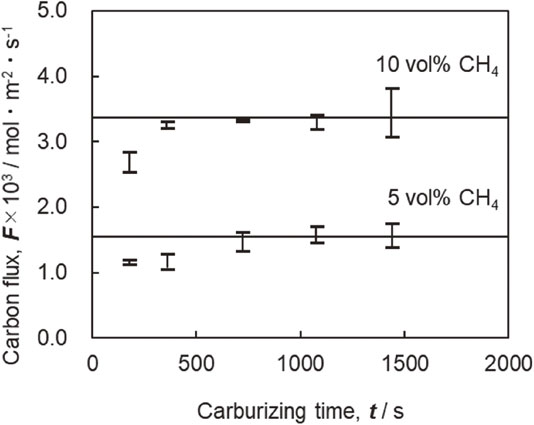
Although the carbon penetration rate shown in Fig. 8 could be regarded as constant, partial melting of some samples occurred depending on the treatment conditions. Therefore, the constancy of the penetration rate during the carburizing process was investigated. Figure 14 shows the relationship between the carbon penetration rate and carburizing time. The carbon penetration rate is nearly constant from 720 s to 1440 s during the carburizing period for each CH4 concentration condition. The same tendency was observed for carburizing times longer than 1440 s, resulting in partial melting of the sample. However, low carbon penetration rates were obtained for carburizing times of 180 s and 360 s in 5% CH4 and 180 s in 10% CH4. This is because low carbon penetration rates result in the early stage of carburizing from the small amount of oxygen remaining after exhausting the air by the rotary pump before treatment. Thus, it was presumed that CH4 was consumed by a reduction reaction of adsorbed O2 at the sample surface, as well as the effect of decarburizing by O2 and steam contained in the refrigerant during quenching.
From the results described above, ultra-rapid carburizing using induction heating at 1523 K produced a constant rate of carbon penetration when the concentration of CH4 during carburizing was constant, indicating that the carbon penetration rate is proportional to the CH4 concentration. Furthermore, the carbon concentration at the sample surface increases with carburizing time, resulting in partial sample melting. The total carburizing depth can be determined using Harris’s empirical formula37) as represented by the parabolic law, regardless of CH4 concentration. The effects of treatment temperature and solidus carbon concentration must be investigated to expand the scope of the study to other processing conditions in the future.
4. Conclusions
The following are the findings of an investigation into the effect of the carburizing atmosphere on carbon penetration characteristics in ultra-rapid carburizing:
-
(1)
Measuring the mass of the sample before and after heat treatment demonstrated that the extent of carbon penetration increased in proportion to the carburizing time, with observed carbon penetration rates of 1.6 × 10⁻³ mol m−2 s−1 in 5% CH4 and 3.4 × 10⁻³ mol m−2 s−1 in 10% CH4, which are proportional to the CH4 concentrations. However, low carbon penetration rates occurred in the early stage of the carburizing process relative to the later stages. Additionally, the carbon penetration rate remained constant, even with partial sample melting.
-
(2)
Observations of the microstructure and the results of measuring surface carbon concentrations by GD–OES revealed that part of the sample melted when the surface carbon concentration reached the solidus.
-
(3)
The total carburizing depth was evaluated based on hardness testing on a cross-section of the sample after ultra-rapid carburizing and quenching, which indicated that the total carburizing depth could be calculated by Harris’s empirical formula, although it is not diffusion-rate-controlled.
-
(4)
In ultra-rapid carburizing at 1523 K, the carburizing time required to obtain the same total carburizing depth can be reduced by 5% on average compared with that at 1203 K, which is the operating temperature of conventional gas carburizing.
REFERENCES
- 1) T. Mizukoshi, Y. Yokoyama, H. Hoshino and I. Ishigami: J. JIME 46 (2011) 669–673. doi:10.5988/jime.46.669
- 2) S.C. Cha, S.H. Hong, M.Y. Kim, J. Park, J.H. Shim, W.S. Jung, M. Rath and E. Kozeschnik: Calphad 54 (2016) 172–180. doi:10.1016/j.calphad.2016.04.008
- 3) Z.K. Qiu, P.Z. Zhang, D.B. Wei, X.F. Wei and X.H. Chen: Surf. Coat. Technol. 278 (2015) 92–98. doi:10.1016/j.surfcoat.2015.08.003
- 4) K. Dychton, P. Rokicki, A. Nowotnik, M. Drajewicz and J. Sieniawski: Solid State Phenom. 227 (2015) 425–428. doi:10.4028/www.scientific.net/SSP.227.425
- 5) I. Ishigami, T. Mizukosi, Y. Yokoyama, H. Hoshino, K. Miura and F. Uratani: Reports of Osaka Pref.: Industrial Research Inst. 21 (2007) 9–16.
- 6) X.X. An, Y. Tian, H.J. Wang, Y.F. Shen and Z.D. Wang: Adv. Eng. Mater. 21 (2019) 1900132. doi:10.1002/adem.201900132
- 7) I. Ishigami, S. Tsuji, F. Uratani and E. Tsunasawa: J. Japan Inst. Metals 50 (1986) 845–851. doi:10.2320/jinstmet1952.50.9_845
- 8) N. Okumura and A. Urase: Netsu Shori (J. Jpn. Heat. Treat.) 38 (1998) 194–197.
- 9) J. Wunning, G. Leyens and G. Woelk: HTM J. Heat Treat. Mater. 31 (1976) 132–137. doi:10.1515/htm-1976-310302
- 10) S.J. Lee, D.K. Matlock and C.J. Van Tyne: ISIJ Int. 51 (2011) 1903–1911. doi:10.2355/isijinternational.51.1903
- 11) M. Zajusz, K. Tkacz-Śmiech and M. Danielewski: Surf. Coat. Technol. 258 (2014) 646–651. doi:10.1016/j.surfcoat.2014.08.023
- 12) S. Makino, M. Inagaki, H. Ikehata, K. Tanaka, H. Inoue and K. Inagaki: Tetsu-to-Hagané 105 (2019) 30–37. doi:10.2355/tetsutohagane.TETSU-2018-108
- 13) T. Tanaka: DENKI-SEIKO 84 (2013) 123–128.
- 14) K. Oobayashi: Spec. Steel 68 (2019) 19–23.
- 15) K. Okada and K. Oobayashi: Netsu Shori (J. Jpn. Heat. Treat.) 56 (2016) 11–15.
- 16) H. Saima: Materia Japan 59 (2020) 486–489. doi:10.2320/materia.59.486
- 17) K. Loeser and B. Gornicki: Gear Technol. 7 (2009) 67–70.
- 18) M. Okumiya, Y. Tunekawa, I. Niimi, M. Hamada and M. Mabe: J. Japan Inst. Metals 55 (1991) 981–985. doi:10.2320/jinstmet1952.55.9_981
- 19) K. Yokose: Spec. Steel 49 (2000) 26–32.
- 20) M.M.A. Bepari: Comprehensive Materials Finishing, 1st, 2, (Elsevier, Amsterdam, 2017) pp. 71–106.
- 21) Y. Yogo and K. Tanaka: Metall. Mater. Trans. A 45 (2014) 2834–2841. doi:10.1007/s11661-014-2233-1
- 22) H. Mohrbacher: Adv. Manuf. 4 (2016) 105–114. doi:10.1007/s40436-016-0142-9
- 23) K. Loeser: Innovative Heat Treating Technologies in the Automotive Industry, (Germany, 2005) pp. 237–244.
- 24) A. Adachi and S. Yamada: J. Surf. Finish. Soc. Jpn. 13 (1962) 487–490. doi:10.4139/sfj1950.13.487
- 25) V. Heuer, K. Loeser and G. Schmitt: Improved Materials and Enhanced Fatigue Resistance for Gear Components, AGMA Technical Paper, 15FTM02. (2015) 1–15.
- 26) G. Hiller: Int. Heat Treat. Surf. Eng. 8 (2014) 35–41. doi:10.1179/1749514813Z.00000000087
- 27) S. Hiramatsu, K. Inagaki, H. Sakaue and I. Yamamotoi: Netsu Shori (J. Jpn. Heat. Treat.) 58 (2018) 54–58. doi:10.14940/netsushori.58.54
- 28) Y.H. Yang, M.Q. Wang, J.C. Chen and H. Dong: J. Iron Steel Res. Int. 20 (2013) 140–145. doi:10.1016/S1006-706X(13)60227-7
- 29) R. Yamamoto and K. Toda: 84th Collected Abstracts of the 2017 Autumn Meeting of The Japan Soc. for Heat Treatment, (2017) pp. 51–52.
- 30) T. Okamoto, A. Matsubara and K. Toda: 84th Collected Abstracts of the 2017 Autumn Meeting of the Japan Soc. for Heat Treatment, (2017) pp. 53–54.
- 31) K.A. Alogab, D.K. Matlock, J.G. Speer and H.J. Kleebe: ISIJ Int. 47 (2007) 1034–1041. doi:10.2355/isijinternational.47.1034
- 32) T. Sasaki: Tetsu-to-Hagané 48 (1962) 1473–1475.
- 33) Z.J. Xu, S.P. Wei, P. Zhou, J.C. Lu and G. Wang: Heat Treat. Met. 39 (2014) 32–35.
- 34) J.W. Zhang, W. Li, H.Q. Wang, Q.P. Song, L.T. Lu, W.J. Wang and Z.G. Liu: Wear 368 (2016) 253–257. doi:10.1016/j.wear.2016.09.029
- 35) Z.Y. Liu, Y.P. Bao, M. Wang, X. Li and F.Z. Zeng: Int. J. Miner. Metall. Mater. 26 (2019) 282–290. doi:10.1007/s12613-019-1736-6
- 36) M. Kubota and T. Ochi: Mater. Sci. Forum 539–543 (2007) 4855–4860. doi:10.4028/www.scientific.net/MSF.539-543.4855
- 37) E.F. Harris: Met. Prog. 44 (1943) 265–272.
- 38) Netsushori-Gijutsu-Binran: The Japan Soc. for Heat Treatment, Japan (2000) 141–144.
- 39) J.H. Kaspersma and R.H. Shay: Metall. Trans. B 13 (1982) 267–273. doi:10.1007/BF02664584
- 40) K.D. Jones and G. Krauss: Heat Treat. 79 (1980) 188–193.
- 41) X.X. An, Y. Tian, H.J. Wang and Z.D. Wang: Mater. Technol. 54 (2020) 551–558. doi:10.17222/mit.2019.298
- 42) R. Tanaka: Tetsu-to-Hagané 53 (1967) 1586–1604. doi:10.2355/tetsutohagane1955.53.14_1586