Abstract
The densification process plays a critical role in determining the microstructure and performance of Ti matrix composites (TMCs). Herein, a comparative study was performed on a graphene oxide (GO)/Ti–6Al–4V composite fabricated by laser powder bed fusion (L-PBF) and spark plasma sintering (SPS). The flexible GO sheets were homogeneously decorated onto the Ti–6Al–4V powders via an electrostatic self-assembly without significantly changing the particle size or sphericity. Under high-energy laser irradiation, the GO sheets were completely dissolved into the matrix. The L-PBF-produced composite was composed of fine α′ martensite structures due to the rapid solidification and the solute carbon atoms. In contrast, the GO was reacted with Ti matrix and completely transformed into submicron TiC particles during SPS; the composite consisted of α + β phases with randomly dispersed TiC. Moreover, the L-PBF-produced composite exhibited a higher hardness of 481 HV as compared with the SPS-produced one of 367 HV, attributing to the fine α′ microstructures and high residual stresses. The present work offers deep understanding on the structural evolution of GO during high-temperature densifications, and shows new insights for fabrication of high-performance TMCs with tailored microstructures.
This Paper was Originally Published in Japanese in J. JILM 72 (2022) 314–320.
1. Introduction
Titanium and its alloys have attracted increasing attention in the aeronautical, chemical, and biomedical industries as promising structural materials, owing to their high strength, superior corrosion resistance, and excellent biocompatibility;1,2) however, their low hardness and poor tribological properties restrict their applications.3,4) In this regard, the fabrication of ceramic particle-reinforced titanium matrix composites (TMCs) is considered an effective way to achieve desirable properties.5) Over the past decade, various types of reinforcements, such as TiC,6) TiB,7) SiC,8) B4C,9) and nanocarbon materials,10) have been attempted.6–10) Among these, graphene is the most promising candidate for fabricating high-performance TMCs owing to its ultrahigh Young’s modulus (1 TPa) and tensile strength (130 GPa).11,12) Graphene/metal matrix composites exhibit significantly improved mechanical properties such as tensile strength and wear resistance.13)
In traditional casting, owing to the tangled nature of graphene sheets and the density discrepancy between graphene and metals, graphene tends to aggregate in the molten metal, resulting in non-uniform microstructures. Therefore, graphene-reinforced TMCs are generally produced using powder metallurgy. Spark plasma sintering (SPS) is a popular densification process for TMCs14) based on the simultaneous application of high pressure and high temperature; it has the advantages of low sintering temperatures, reduced sintering time, negligible grain growth, and energy conservation.15–17) Ge et al. combined SPS and hot rolling to fabricate TMCs reinforced by nickel-coated graphene nanoflakes (Ni-GNFs); these exhibited a high tensile strength of 821 MPa and high ductility of 18.3%, showing good strength-plasticity compatibility.18) Even though powder metallurgy has proven to be an effective fabrication route for TMCs, some processing problems still exist. For instance, time- and energy-consuming post-treatments, such as plastic working or machining, are typically required to obtain customized architectures and desired properties.19) Moreover, the high chemical reactivity of Ti causes oxidation of the metal matrix, which is detrimental to the machinability of TMCs.20)
Laser powder bed fusion (L-PBF), an additive manufacturing technology, has attracted increasing attention to fabricate metallic components.21,22) It uses a high-energy laser beam to melt and consolidate the powder bed in predefined scan paths according to the corresponding computer-aided design (CAD) files.19,23) This procedure continues in a layer-by-layer manner until the desired three-dimensional structures are fabricated.24) Compared with conventional casting and powder metallurgy, L-PBF has many advantages, such as the direct production of complex structures, less time consumption, low tooling costs, and high dimensional precision.25) Noteworthily, L-PBF is not only a promising manufacturing process but also a synthesis technique that provides new opportunities for producing high-performance metallic composites. For instance, owing to rapid solidification (∼103–108 K·s−1) induced by high-energy laser irradiation, L-PBF-processed composites exhibit ultrafine microstructures and promising properties.26–28) However, the microstructure and mechanical performance of additive-manufactured graphene-reinforced TMCs have not been studied extensively.29)
The performance of L-PBF products is highly related to the properties of the powders used. These powders should possess high sphericity, appropriate particle size distribution, and good flowability.30) However, composite powders prepared by conventional ball milling generally exhibit poor flowability owing to the uncontrollable powder size and sphericity, leading to internal defects in the final products. Herein, hetero-agglomeration is proposed to be a promising process for powder fabrication. It uses the electrostatic attraction between charged particles to achieve uniform dispersion.31) Considering the ultrathin and flexible features of graphene, graphene-decorated metallic powders prepared by hetero-agglomeration can retain their original particle size and sphericity, producing high-performance TMCs via L-PBF.
The densification process plays a critical role in determining the microstructures of TMCs, for example, the dispersion state of fillers, interfacial bonding, or texture information of the matrix, consequently influencing their properties. Therefore, in this study, two typical densification processes, L-PBF and SPS, were employed to fabricate graphene oxide (GO)-reinforced Ti–6Al–4V composites. The structural evolution mechanism of GO during high-temperature densification was clarified. Mechanical performance of the two TMCs was compared and discussed based on microstructural observations.
2. Experimental
2.1 Starting materials and preparation of GO/Ti–6Al–4V powders
Ti–6Al–4V alloy powders were prepared via gas atomization. A GO colloid with ∼1 mass% concentration was synthesized using a modified Hummers’ method.32) The GO-decorated Ti–6Al–4V powders were prepared via hetero-agglomeration. An appropriate quantity of GO colloid was first dispersed in 100 mL deionized water by mechanical stirring and ultrasonication in an ice-water bath for 0.33 h. Ti–6Al–4V powder (50 g) was added to the dilute GO colloid and then mechanically blended for 1 h. Subsequently, the mixed slurry was dropped into liquid nitrogen for rapid freezing. After complete drying in a vacuum furnace at 228 K for 72 h, a 0.5 mass% GO/Ti–6Al–4V powder mixture was obtained.
2.2 L-PBF processing of GO/Ti–6Al–4V powders
A commercial laser cusing system (Concept Laser MlabR, Germany) equipped with an ytterbium fiber laser source (wavelength: 1070 nm) was employed to produce the GO/Ti–6Al–4V composite builds. The optimized L-PBF parameters (laser power: 95 W, scanning speed: 1000 mm·s−1, hatch distance: 90 µm, layer thickness: 25 µm) and typical “island scanning strategy”26) were used for bulk fabrication. The building process was carried out under a protective Ar atmosphere with low oxygen content (<0.1%). Cylindrical builds (diameter = 6 mm, length = 10 mm, labeled L-PBF-ed) were obtained using L-PBF.
2.3 SPS processing of GO/Ti–6Al–4V powders
The GO/Ti–6Al–4V powders were also consolidated by SPS (Dr. Sinter S511, Sumitomo Coal Mining Co., Ltd.). A carbon die with an inner diameter of 6 mm and a height of 60 mm was used for SPS. The sintering temperature, holding time, and applied pressure were 1373 K, 300 s, and 50 MPa, respectively. Cylindrical bulks (diameter = 6 mm, length = 10 mm, labeled SPS-ed) were obtained using SPS.
2.4 Microstructural and mechanical characterizations
Microstructures of the GO sheets, composite powders, and bulk samples were characterized using field emission scanning electron microscopy (FE-SEM; JSM-6500F, JEOL, Japan), electron probe microanalysis (EPMA; JXA-8530F, JEOL, Japan), transmission electron microscopy (TEM; HF-2000EDX, Hitachi, Japan), and scanning TEM (STEM; JEM-ARM200F, JEOL, Japan). Phase composition was measured using X-ray diffraction (XRD; SmartLab 9 kW, Rigaku, Japan) with Cu Kα radiation. The apparent densities of the bulk specimens were measured using Archimedes’ principle. The relative densities were calculated by the densities of the bulk specimens to the theoretical density of Ti–6Al–4V alloy (4.43 g·cm−3). The Vickers hardness of the bulk samples was measured using a microzone tester (MZT-500, Mitutoyo Co. Ltd., Japan). The indenter was loaded to peaks of 500, 750, or 1000 mN at a loading rate of 50 mN/s.
3. Results and Discussion
3.1 Characteristics of GO/Ti–6Al–4V mixed powders
Typical morphologies of the as-prepared GO sheets are shown in Fig. 1. GO shows a dark contrast on the silica glass. As confirmed by the FE-SEM observations in Fig. 1(a), the lateral size of the irregular GO was ∼1 µm. As indicated by the red arrow in Fig. 1(b), GO tended to wrinkle because of its ultrathin dimensions, resulting in remarkable flexibility.
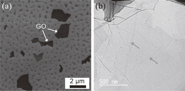
Figure 2(a) shows the morphology of starting Ti–6Al–4V powders. The Ti–6Al–4V powders used in this study were nearly spherical, with an average particle size of ∼14 µm. Certain amounts of satellite particles induced by gas atomization were tightly attached to the spherical powders. The morphology of 0.5 mass% GO/Ti–6Al–4V mixed powders is shown in Fig. 2(b). Owing to the ultrathin and flexible features of the incorporated GO,33) the spherical shape of 0.5 mass% GO/Ti–6Al–4V mixed powders was retained, and their particle size or distribution was similar to that of the starting powders. The unchanged powder morphology may benefit the flowability of the GO/Ti–6Al–4V particles, making them suitable for L-PBF.

A typical GO-decorated Ti–6Al–4V particle was confirmed via high-magnification FE-SEM images and the corresponding energy dispersive X-ray spectroscopy (EDS) analysis in Fig. 2(c)–(d). As shown by the yellow arrows in Fig. 2(c), the GO sheets were attached uniformly to the Ti–6Al–4V particles without apparent agglomeration. Various studies report that numerous functional groups, such as tertiary alcohols, ethers, and carboxyl groups, are present on the surface of GO sheets; thus, they exhibit a negative charge in solvents.34,35) In contrast, a thin oxide film generally exists on the surface of gas-atomized Ti–6Al–4V particles. Such oxides can preferentially adsorb H+ ions in water, leading to a positively charged surface.36) Therefore, during the hetero-agglomeration process, the negatively charged GO and positively charged Ti–6Al–4V powders are attracted under an electrostatic force.
3.2 Microstructure of L-PBF-ed GO/Ti–6Al–4V composite
After L-PBF, a dense GO/Ti–6Al–4V composite was successfully fabricated. The measured relative density was approximately 99.6%. The phase constitution was evaluated using XRD analysis, as shown in Fig. 3. Similar to the starting Ti–6Al–4V powders, the composite mainly comprised a hexagonal close-packed structure corresponding to the α/α′-Ti phase. It is difficult to directly differentiate the α- and α′-Ti phases by XRD because of the same crystalline structure and similar lattice parameters.37) In addition, there was no peaks of TiC or β-Ti detected in the XRD pattern of the composite.

Figure 4(a) shows the FE-SEM image of a chemically etched surface of the L-PBF-ed GO/Ti–6Al–4V composite. Pores or cracks were not observed in the composite, showing that the addition of GO did not significantly influence the densification behavior of the Ti–6Al–4V alloy during L-PBF. Moreover, the composite was composed of uniform, fine acicular structures corresponding to α′ martensite. As confirmed by the EPMA mappings in Fig. 4(b) and the TEM-EDS mappings in Fig. 5, elemental Ti, Al, V, and C were distributed homogeneously in the composite without microsegregation.
The magnified TEM observations in Fig. 6(a) reveal the presence of abundant thermal stress or dislocations in the α′ structure. Due to the rapid cooling rates of the L-PBF process, the previous β phase of the Ti–6Al–4V alloy was transformed into the α′ phase by shear-type transformation.38) The yellow arrow in Fig. 6(b) shows a typical prior-β grain boundary.

However, residual GO sheets and carbide precipitates were not detected by careful TEM and STEM observations. Because the entire L-PBF process was performed in an Ar gas protective atmosphere, the oxidation and evaporation of GO sheets hardly occurred. It is believed that GO decomposed and dissolved into the matrix during the L-PBF process. Thus, uniform dispersion of elemental C was observed in the composite, as shown from the EPMA and TEM-EDS analyses (Figs. 4 and 5). The thermal stability of perfect graphene is extremely high; thus, it can retain its crystalline structure at the evaluated temperatures.39) In contrast, the starting GO sheets had many intrinsic defects, such as dangling carbon bonds or chemical etching-induced nanopores, as well as surface oxygen-containing groups; thus, their thermal stability dramatically decreased under ultrahigh temperatures.40) The structural evolution of GO during L-PBF is discussed in Section 3.4.
3.3 Microstructure of SPS-ed composite
A dense 0.5 mass% GO/Ti–6Al–4V composite with a relative density of approximately 99.8% was obtained via SPS. The typical morphology of a SPS-ed GO/Ti–6Al–4V composite is shown in Fig. 7(a). The matrix mainly comprised two types of lamellar structures with gray or white contrast. According to the EPMA mappings in Fig. 8, the gray- and white-contrasted areas were elemental Al- or V-rich, respectively. Elemental Al or V are stabilizers of the α or β phases in Ti alloys.41) Thus, the gray- or white-contrasted areas correspond to the α- or β-Ti phases, respectively. This result was consistent with the XRD analysis shown in Fig. 3. Since the SPS temperature (1373 K) was higher than the β-Ti transition temperature (∼1273 K for Ti–6Al–4V),42) the alloy matrix first transformed into the β phase during sintering. Subsequently, the β phase gradually decomposed into lamellar α + β phases during the cooling stage.
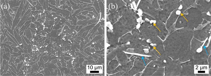

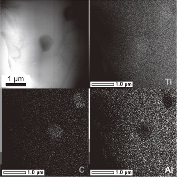
Notably, some spherical (yellow arrows) and needle-like precipitates (blue arrows) are randomly distributed at the grain boundaries, as shown in Fig. 7(b). The TEM-EDS mappings in Fig. 9 revealed that the precipitates mainly comprised elemental Ti and C. Figure 10(a) shows the TEM image of a precipitate particle. As distinguished by the selected area electron diffraction (SAED) pattern along the [1-1-1] zone axis in Fig. 10(b), these particles are submicron TiC single crystals that possess a low-indexed, faceted interface with the matrix. The HRTEM image and corresponding fast Fourier transform (FFT) patterns in Fig. 11 illustrate the typical orientation relationships at the TiC–Ti interface, that is, [001] TiC // [0001] α-Ti // [-111] β-Ti and (200) TiC // (01-10) α-Ti // (01-1) β-Ti. This result suggests that the TiC particles formed a stable and coherent interface with the matrix via an in-situ reaction.
According to the calculation results of Yi et al.,43) the Gibbs free energy (ΔG) of TiC formation is negative, indicating that GO reacts spontaneously with Ti at elevated temperatures. Thus, the reaction between GO and the Ti matrix occurred during solid-state SPS as follows:
| \begin{equation}
\text{Ti} + \text{C}\to \text{TiC}
\end{equation}
| (1) |
As shown in Fig. 7, the generated TiC particles did not retain the original shape of GO. This result reveals that the GO structures underwent a dissolution/precipitation process during SPS, which is consistent with the report by Li et al.44)
3.4 Microstructural evolution mechanisms of GO during SPS and L-PBF
The state of the fillers is significantly influenced by the initial dispersion of the mixed powders and the densification process.45,46) Even though the same GO/Ti–6Al–4V mixed powders were used for SPS and L-PBF, the eventual forms of the carbon structures were distinct (Figs. 6 and 10, respectively). This was caused by the evolution discrepancy of the GO structures, as illustrated schematically in Fig. 12.

The GO/Ti–6Al–4V mixed powders were produced by hetero-agglomeration, because of which, GO was tightly covered on the Ti–6Al–4V powder surface. Owing to the large dimensional or size difference between the GO and Ti–6Al–4V powders, the GO sheets existed only on the surface of Ti–6Al–4V powders; thus, the GO/Ti–6Al–4V powders were not assembled homogeneously. During solid-state sintering, the GO sheets were retained at the primary particle boundaries rather than in the grains. Furthermore, there were confined contact areas between GO and the Ti–6Al–4V matrix. Thus, the dissolution of GO was limited to the vicinity of the alloy matrix during the rapid SPS densification, resulting in highly carbon-supersaturated zones. Subsequently, boundary-type TiC nuclei were generated and grew in the lamellar α + β phases during the cooling process (Fig. 12(b)).
In contrast, under high-energy laser irradiation of L-PBF, the GO structures tended to decompose, and the diffusion of carbon atoms was significantly accelerated in the metal liquids. More importantly, the Marangoni convection introduced by the steep temperature gradient promoted the rearrangement of carbon atoms within the micron-scale molten pools.47,48) Accompanied by the rapid cooling process, the carbon atoms were homogeneously solubilized in the continuously solidified micron-zones of the L-PBF-ed composite without the SPS-induced locally carbon-supersaturated areas. Subsequently, the formation of fine α′ structures occurred during the rapid densification process without TiC nucleation (Fig. 12(a)). In addition, the size of the martensite structures was smaller than the Ti–6Al–4V alloy builds, attributed to the solubilization of carbon atoms.
3.5 Mechanical properties and strengthening mechanism
The mechanical performance of the GO/Ti–6Al–4V composite was evaluated via indentation tests. Figures 13(a), (b) compare the indentation load-depth curves of L-PBF-ed and SPS-ed GO/Ti–6Al–4V composites under loads of 500, 750, and 1000 mN, respectively. The penetration depth increased with increasing applied load. Furthermore, the maximum penetration depth of the L-PBF-ed GO/Ti–6Al–4V composite was smaller than that of the SPS-ed composite subjected to the same loads. Correspondingly, as summarized in Fig. 13(c), the L-PBF-ed composite exhibited a higher hardness (481 ± 12 HV) than the SPS-ed composite (367 ± 8 HV). Since both the L-PBF-ed and the SPS-ed composites exhibited high relative densities of >99.5%, the higher hardness was primarily attributed to the solid solution of carbon and fine α′ structure formed in the L-PBF-ed composite.
4. Conclusions
A comparative study was performed on the microstructure and mechanical performance of a GO/Ti–6Al–4V composite fabricated using L-PBF and SPS. The main conclusions are summarized as follows.
-
(1)
The GO sheets were uniformly decorated onto the surface of the Ti–6Al–4V particles under electrostatic force during hetero-agglomeration. The GO/Ti–6Al–4V composite powders retained their spherical morphology and similar particle size and distribution as the Ti–6Al–4V powders, being suitable for L-PBF.
-
(2)
A GO/Ti–6Al–4V composite with a relative density of 99.6% was fabricated successfully by L-PBF. The GO sheets were completely dissolved into the Ti matrix without carbide formation under laser irradiation. The L-PBF-ed composite was composed of fine α′ martensite structures owing to the rapid densification and the solid solution of carbon atoms.
-
(3)
The SPS-ed GO/Ti–6Al–4V composite consists of α + β phases with randomly dispersed TiC particles. The GO sheets reacted with the matrix and were completely transformed into submicron TiC particles. The in-situ TiC was a single crystal with a low-indexed, faceted interface with the matrix. The orientation relationships at the TiC–Ti interface are [001] TiC // [0001] α-Ti // [-111] β-Ti and (200) TiC // (01-10) α-Ti // (01-1) β-Ti.
-
(4)
The L-PBF-ed composite exhibited a higher hardness of 481 HV than the SPS-ed one of 367 HV, primarily attributed to the fine α′ microstructures and solid solution of the L-PBF-ed composite. The present work offers a deeper understanding of the structural evolution of GO during L-PBF and SPS and provides new insights for the fabrication of advanced TMCs with unique microstructures.
REFERENCES
- 1) G. Welsch, R. Boyer and E. Collings: Materials Properties Handbook: Titanium Alloys, (ASM International, 1993).
- 2) H. Attar, S. Ehtemam-Haghighi, N. Soro, D. Kent and M. Dargusch: J. Alloy. Compd. 827 (2020) 154263. doi:10.1016/j.jallcom.2020.154263
- 3) S. Li, B. Sun, H. Imai, T. Mimoto and K. Kondoh: Compos. Part A 48 (2013) 57–66. doi:10.1016/j.compositesa.2012.12.005
- 4) T. Kuzumaki, O. Ujiie, H. Ichinose and K. Ito: Adv. Eng. Mater. 2 (2000) 416–418. doi:10.1002/1527-2648(200007)2:7%3C416::AID-ADEM416%3E3.0.CO%3B2-Y
- 5) L. Huang, Q. An, L. Geng, S. Wang, S. Jiang, X. Cui, R. Zhang, F. Sun, Y. Jiao and X. Chen: Adv. Mater. 33 (2021) 2000688. doi:10.1002/adma.202000688
- 6) J. Qi, Y. Sui, Y. Chang, Y. He, F. Wei, Q. Meng and Z. Wei: Vacuum 126 (2016) 1–4. doi:10.1016/j.vacuum.2015.12.021
- 7) S. Li, K. Kondoh, H. Imai, B. Chen, L. Jia, J. Umeda and Y. Fu: Mater. Des. 95 (2016) 127–132. doi:10.1016/j.matdes.2016.01.092
- 8) M. Das, V.K. Balla, D. Basu, S. Bose and A. Bandyopadhyay: Scr. Mater. 63 (2010) 438–441. doi:10.1016/j.scriptamat.2010.04.044
- 9) J. Wang, X. Guo, J. Qin, D. Zhang and W. Lu: Mater. Sci. Eng. A 628 (2015) 366–373. doi:10.1016/j.msea.2015.01.067
- 10) Z. Cao, X. Wang, J. Li, Y. Wu, H. Zhang, J. Guo and S. Wang: J. Alloy. Compd. 696 (2017) 498–502. doi:10.1016/j.jallcom.2016.11.302
- 11) C. Lee, X. Wei, J.W. Kysar and J. Hone: Science 321 (2008) 385–388. doi:10.1126/science.1157996
- 12) K. Chu, F. Wang, X.H. Wang, Y.B. Li, Z.R. Geng, D.J. Huang and H. Zhang: Mater. Des. 144 (2018) 290–303. doi:10.1016/j.matdes.2018.02.038
- 13) H.C. Cao and Y.L. Liang: J. Alloy. Compd. 812 (2020) 152057. doi:10.1016/j.jallcom.2019.152057
- 14) Z.Y. Hu, Z.H. Zhang, X.W. Cheng, F.C. Wang, Y.F. Zhang and S.L. Li: Mater. Des. 191 (2020) 108662. doi:10.1016/j.matdes.2020.108662
- 15) S.M. Bagheri, M. Vajdi, F.S. Moghanlou, M. Sakkaki, M. Mohammadi, M. Shokouhimehr and M.S. Asl: Ceram. Int. 46 (2020) 7615–7624. doi:10.1016/j.ceramint.2019.11.262
- 16) T. Gholizadeh, M. Vajdi and F. Mohammadkhani: Energy Convers. Manage. 181 (2019) 463–475. doi:10.1016/j.enconman.2018.12.011
- 17) Y. Achenani, M. Saâdaoui, A. Cheddadi, G. Bonnefont and G. Fantozzi: Mater. Des. 116 (2017) 504–514. doi:10.1016/j.matdes.2016.12.054
- 18) Y.X. Ge, H.M. Zhang, X.W. Cheng, Q.B. Fan, Z.H. Zhang, X.N. Mu and L. Liu: J. Alloy. Compd. 893 (2022) 162240. doi:10.1016/j.jallcom.2021.162240
- 19) T. DebRoy, H.L. Wei, J.S. Zuback, T. Mukherjee, J.W. Elmer, J.O. Milewski, A.M. Beese, A. Wilson-Heid, A. De and W. Zhang: Prog. Mater Sci. 92 (2018) 112–224. doi:10.1016/j.pmatsci.2017.10.001
- 20) H. Attar, M. Bönisch, M. Calin, L.C. Zhang, S. Scudino and J. Eckert: Acta Mater. 76 (2014) 13–22. doi:10.1016/j.actamat.2014.05.022
- 21) M. Simonelli, Y.Y. Tse and C. Tuck: Mater. Sci. Eng. A 616 (2014) 1–11. doi:10.1016/j.msea.2014.07.086
- 22) Z. Zhou, S. Guo, W. Zhou and N. Nomura: Sci. Rep. 11 (2021) 16576. doi:10.1038/s41598-021-96187-w
- 23) S. Liu and Y.C. Shin: Mater. Des. 164 (2019) 107552. doi:10.1016/j.matdes.2018.107552
- 24) Q. Jia, P. Rometsch, P. Kürnsteiner, Q. Chao, A. Huang, M. Weyland, L. Bourgeois and X. Wu: Acta Mater. 171 (2019) 108–118. doi:10.1016/j.actamat.2019.04.014
- 25) C. Cai, C. Radoslaw, J. Zhang, Q. Yan, S. Wen, B. Song and Y. Shi: Powder Technol. 342 (2019) 73–84. doi:10.1016/j.powtec.2018.09.088
- 26) B. Cheng, S. Shrestha and K. Chou: Addit. Manuf. 12 (2016) 240–251. doi:10.1016/j.addma.2016.05.007
- 27) P. Krakhmalev, G. Fredriksson, I. Yadroitsava, N. Kazantseva, A. du Plessis and I. Yadroitsev: Phys. Procedia 83 (2016) 778–788. doi:10.1016/j.phpro.2016.08.080
- 28) B. Chen, S. Moon, X. Yao, G. Bi, J. Shen, J. Umeda and K. Kondoh: Scr. Mater. 141 (2017) 45–49. doi:10.1016/j.scriptamat.2017.07.025
- 29) Q. Yan, B. Chen and J. Li: Carbon 174 (2021) 451–462. doi:10.1016/j.carbon.2020.12.047
- 30) S.E. Brika, M. Letenneur, C.A. Dion and V. Brailovski: Addit. Manuf. 31 (2020) 100929. doi:10.1016/j.addma.2019.100929
- 31) W. Zhou, X. Sun, K. Kikuchi, N. Nomura, K. Yoshimi and A. Kawasaki: Mater. Des. 137 (2018) 276–285. doi:10.1016/j.matdes.2017.10.034
- 32) J.C. Meyer, A.K. Geim, M.I. Katsnelson, K.S. Novoselov, T.J. Booth and S. Roth: Nature 446 (2007) 60–63. doi:10.1038/nature05545
- 33) C. Zhu, S. Guo, Y. Fang and S. Dong: ACS Nano 4 (2010) 2429–2437. doi:10.1021/nn1002387
- 34) D.C. Marcano, D.V. Kosynkin, J.M. Berlin, A. Sinitskii, Z. Sun, A. Slesarev, L.B. Alemany, W. Lu and J.M. Tour: ACS Nano 4 (2010) 4806–4814. doi:10.1021/nn1006368
- 35) K. Krishnamoorthy, M. Veerapandian, K. Yun and S.J. Kim: Carbon 53 (2013) 38–49. doi:10.1016/j.carbon.2012.10.013
- 36) W. Zhou, K. Kamata, M. Dong and N. Nomura: Powder Technol. 382 (2021) 274–283. doi:10.1016/j.powtec.2020.12.066
- 37) X. Zhao, S. Li, M. Zhang, Y. Liu, T.B. Sercombe, S. Wang, Y. Hao, R. Yang and L.E. Murr: Mater. Des. 95 (2016) 21–31. doi:10.1016/j.matdes.2015.12.135
- 38) J. Yang, H. Yu, J. Yin, M. Gao, Z. Wang and X. Zeng: Mater. Des. 108 (2016) 308–318. doi:10.1016/j.matdes.2016.06.117
- 39) A.S. Barnard and I.K. Snook: J. Chem. Phys. 128 (2008) 094707. doi:10.1063/1.2841366
- 40) J. Song, X. Wang and C.T. Chang: J. Nanomater. 2014 (2014) 276143. doi:10.1155/2014/276143
- 41) W. Xu, E.W. Lui, A. Pateras, M. Qian and M. Brandt: Acta Mater. 125 (2017) 390–400. doi:10.1016/j.actamat.2016.12.027
- 42) S.G. Tabrizi, S.A. Sajjadi, A. Babakhani and W. Lu: J. Alloy. Compd. 692 (2017) 734–744. doi:10.1016/j.jallcom.2016.09.026
- 43) M. Yi, X. Zhang, G. Liu, B. Wang, H. Shao and G. Qiao: Mater. Charact. 140 (2018) 281–289. doi:10.1016/j.matchar.2018.04.010
- 44) S. Li, B. Sun, H. Imai and K. Kondoh: Carbon 61 (2013) 216–228. doi:10.1016/j.carbon.2013.04.088
- 45) D. Pan, X. Zhang, X. Hou, Y. Han, M. Chu, B. Chen, L. Jia, K. Kondoh and S. Li: Mater. Sci. Eng. A 799 (2021) 140137. doi:10.1016/j.msea.2020.140137
- 46) M. Selvakumar, P. Chandrasekar, M. Mohanraj, B. Ravisankar and J.N. Balaraju: Mater. Lett. 144 (2015) 58–61. doi:10.1016/j.matlet.2014.12.126
- 47) M. Bayat, A. Thanki, S. Mohanty, A. Witvrouw, S. Yang, J. Thorborg, N.S. Tiedje and J.H. Hattel: Addit. Manuf. 30 (2019) 100835. doi:10.1016/j.addma.2019.100835
- 48) M. Dong, W. Zhou, K. Kamata and N. Nomura: Mater. Charact. 170 (2020) 110678. doi:10.1016/j.matchar.2020.110678


