Abstract
Flash sintering was first reported in 2010 by a research group of Raj et al. at Colorado University. Since then, flash sintering has attracted attention as an innovative sintering method that uses the steep power spike, generated when ceramic green compact is heated while an electric field, is applied to densify ceramic green compact in an instant. However, there are several technical challenges that must be overcome before flash sintering can be used as a practical sintering method. This paper outlines the problems and improvements related to flash sintering from a viewpoint of sintering method and introduces the improved flash sintering noted as shrinkage-rate controlled flash sintering developed by the author.
This Paper was Originally Published in Japanese in J. Jpn. Soc. Powder Powder Metallurgy 70 (2023) 18–29.
1. Introduction
In 1897, Walther Hermann Nernst of Germany discovered that pressed oxide powder emits light when heated and subjected to an electric field above a threshold value.1) He proposed the use of this phenomenon as an incandescent lamp at that time, called the Nernst lamp. Although its usefulness was recognized, it was not put into practical use at the time because of its complicated structure. The “phenomenon of oxide luminescence” discovered by W.H. Nernst has attracted renewed attention over time under the name of “flash”.2) This paper focuses on flash sintering, which applies this flash phenomenon to sintering ceramics.
Raj and his research group at the University of Colorado, USA, applied this luminescence phenomenon to sintering technology and published a paper in the Journal of the American Ceramic Society in 2010 as a new sintering method capable of densifying ceramics in a short time.3) After 10 years, more than 1,200 papers related to flash sintering have been published to date. Numerous findings that could not be clarified in Nernst’s time have been accumulated.4–10) When flash sintering was first published, the phenomenon was vaguely interpreted as simple thermal runaway caused by the negative temperature dependence of the electrical conductivity of oxides.11) However, many experimental results were found that could not be understood as simple thermal runaway, such as the above-mentioned luminescence,2,12) phase transformation and abnormal expansion during flash,13–16) variations in fluorescence emission properties,17–19) and the existence of incubation time in flash phenomena.20–22)
Flash sintering is expanding beyond the framework of sintering research and into the investigation of new physical phenomena induced by the application of an electric field. However, the instantaneous densification that occurs at lower furnace temperatures is extremely attractive for sintering technologies. Furthermore, flash sintering does not require large experimental equipment, such as a hot press or hot isostatic press, and can be simply performed by connecting a power supply to the ceramic powder compact.
This paper provides a review of the recent advances in flash sintering from the viewpoint of practical application that was performed by the author’s research group. There have already been many commentaries and reviews on the flash sintering method. For details, please refer to those references.4–10)
2. Overview of Flash Sintering
In flash sintering, a ceramic green compact is placed in a furnace with electrodes and lead wires designed to apply an electric field, and the temperature is raised while an electric field is applied.4–9) Figure 1 shows a schematic diagram of the process.5) A direct current (DC) power supply is commonly used as the power source, but an alternating current (AC) power supply is more suitable for obtaining uniform densification and microstructure as described later. As explained in Fig. 2, a highly controllable power supply is required because a steep current increase occurs at the onset of flash event. In this sense, it is not easy to select a model of AC stabilized power supply. The characteristic shape of a green compact shown in Fig. 1(a), called a dog-bone, is often used to facilitate the application of a high electric field. The slightly larger electrode part is connected to a thin gauge part. Pt wire is threaded through the hole used for electrode and green compact is suspended in the furnace by this Pt wire. In the case of single crystals, Pt wire is sometimes wrapped around both ends of a thin rectangular shape, as shown in Fig. 1(b). In the case of the more common rectangular shape shown in Fig. 1(c), Pt foil is fixed as electrodes on both end faces of the green compact, and Pt wires are attached to these electrodes as lead wires. In either case, the lead wires are connected to the power supply, and the temperature is then simply raised while voltage is applied. In the case of the dog-bone shape shown in Fig. 1(a), the densification behavior during flash sintering is measured by recording the shape change as an image using a CCD camera and measuring the length change of the gauge section from the image. The author has modified a commercially available differential thermal dilatometer to measure the length change in real time using the green compact shown in Fig. 1(c). In any case, there is no specific method. It is sufficient if an electric field can be applied and if the time trends of electrical properties and the shape of the green compact can be measured.

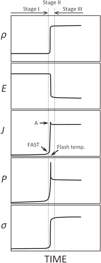
Figure 2 shows a schematic illustration of the time evolution for typical parameters in flash sintering. As the temperature of the ceramic green compact is increased under an applied electric field, the sample electric current slightly increases, and the rate of increase eventually increases to a rapid flash event, followed by a transition to a steady state. The furnace temperature at which the flash event occurs is called the flash temperature, which decreases with the applied electric field. The expression “a steep increase in electric current” is often used to describe flash sintering; however, the more appropriate term is a steep increase in electric power. The temperature of the green compact significantly increases above the furnace temperature because of the power input during flash events. Therefore, as is the case with many oxides, the electrical conductivity significantly increases with the temperature rise. As the sample electric current reaches the limit value set by a power supply during a flash event, the electric field rapidly decreases with the increase in conductivity. Stage I is the period before the onset of the flash event, Stage II is the period just before/after the onset of the flash event when the current value significantly increases, and Stage III is the period after the onset of the flash event when the conductivity becomes approximately constant.23) The region of gradually increasing electric current that appears before Stage II is sometimes called the FAST region.24) However, the boundaries between each stage are not always strictly classified.
In Stages I–III, the power supply connected to the green compact operates as follows: In Stage I, the power supply is driven in a constant-voltage control mode with a preset current limit value. During a flash event, the sample electric current rapidly increases, and when it reaches the preset electric current limit, the power supply switches to a constant-current control mode, and the sample electric current is driven at a constant value thereafter. The flash sintering method shown in Fig. 2 is often called the voltage-to-current method (sometimes called original flash sintering),25) focusing on the control state of the power supply during the flash sintering process. Because the amount of shrinkage of the green compact largely depends on the amount of power input applied during a flash event, the larger the preset electric current limit in a constant-voltage control mode, the more the amount of shrinkage can increase. However, the maximum value is limited by the melting point of the Pt wire or Pt foil used for setting the sample. The magnitude of the electric power spike during a flash event also depends on the controllability of the power supply. The current value during a flash event is not always correctly controlled at the electric current limit set by the power supply, and in many cases, overshoot occurs. Excessive overshoot is a detrimental factor that prevents uniform structure and densification. When the current limit is set lower to suppress the overshoot, the amount of available electric power to densify the green compact in Stages II and III can become insufficient. In the author’s experience, this overshoot tends to increase in oxides containing transition metals such as BaTiO3, SrTiO3, and TiO2. This is probably related to the mobility of the carriers responsible for electrical conduction and the ease of oxygen vacancy formation induced by the electric field.
3. Effects of Using Direct Current Electric Fields
DC power supplies are widely used in flash sintering owing to the controllability of the steep power (current) increase that occurs during flash sintering and its convenience. However, when a DC electric field is used, oxygen ion diffusion in one direction is strongly induced, resulting in a strong reduction effect, which causes non-uniform densification, a decrease in attained density, and nitriding in air.26) Figure 3 shows the grain boundary structure of pure zirconia that was flash sintered without any stabilizer additives using a DC electric field. Figure 3(a) shows a scanning electron microscopy (SEM) image showing the microstructure of grain boundary planes when the DC flash-sintered compact was broken to reveal the grain boundary,27) and the second phases formed on the grain boundary planes are observed. Transmission electron microscopy (TEM) of the grain boundary shows the formation of an amorphous layer with a width of approximately 20–50 nm, as shown in Fig. 3(b), and the oxygen K-edge electron energy-loss near edge structure (ELNES) in Fig. 3(c) shows that the peak separation observed within the grain becomes obscured in the amorphous region. The change in bonding state is attributed to oxygen deficiency.27) This may be due to the strong reduction of pure zirconia by the DC electric field. The amorphous phase was formed by the excess oxygen vacancies that increase in concentration at the grain boundaries under a DC electric field.

Figure 4 shows the nitriding phenomenon of partially stabilized zirconia (3 mol%Y2O3–ZrO2, 3YSZ) that occurs during flash sintering under a DC electric field in air.26,28) Depending on the DC electric field conditions, gold-colored fine particles are formed on the surface and inside the flash sintered compact, as shown in the optical photograph of Fig. 4(a). These gold-colored particles have characteristic shapes with white contrast in high-angle annular dark field scanning TEM (HAADF-STEM) images, as shown in Fig. 4(b). Nitrogen is confirmed in these particles, as shown in energy dispersive X-ray spectroscopy (EDS) mapping images of Fig. 4(c) and (d). Electron diffraction and electron energy loss spectroscopy (EELS) confirm that most of these particles are ZrN.26,28) Depending on the DC electric field conditions, the oxynitride particles, which are considered to be formed in the nitridation process, have also been observed. In partially stabilized zirconia ceramics, which are often used as structural ceramics, the formation of such nitrides is undesirable in terms of strength.

Strong reduction under a DC electric field often causes critical defects in oxide ceramics containing transition metals. The formation of oxygen vacancies by strong reduction generates electrons that significantly increase electrical conductivity.29) This increase in electrical conductivity induces a further concentration of the electric current flow, and the chain of these events eventually results in a discharge. Figure 5 shows the microstructures near the discharge hole generated during DC flash sintering of BaTiO3.30,31) A discharge hole, as shown in Fig. 5(a), appears in various forms depending on the electric field conditions. Although the discharge occurs instantaneously, grain coarsening is observed in the region adjacent to the discharge hole, as shown in Fig. 5(b). Because many residual pores are incorporated inside the grains, it is expected that grain growth is enhanced by the instantaneous heat generated by the discharge during the densification process. Figure 5(c) shows a TEM bright-field image of this region. A second phase formed at the grain boundary, as indicated by the black arrow, which is always observed in darker contrast when observed by HAADF-STEM. This indicates that a compositional change from BaTiO3 has occurred. The quantitative measurement using EELS confirms that this second phase is a non-equilibrium phase with a different Ba/Ti ratio, formed by the decomposition of BaTiO3 during discharge. Evaporation of some Ba occurs during discharge and the area is subsequently quenched at the moment that the power supply is switched off.30) Notably, the grains in contact with this second phase maintain the crystal structure of BaTiO3, as shown in Fig. 5(c) and (d). This result suggests that the electric current concentrates along grain boundaries and results in local heating.

As described above, the use of a DC electric field is not preferable when considering practical sintering applications. As discussed in the next section, it is essential to use an AC electric field with a high frequency for flash sintering.
4. Comparison of DC and AC Electric Fields on Sintering Behavior
Figure 6 compares the effects of DC and AC electric fields on the shrinkage behaviors of sintered compact with the enlarged dimensions of the green compact to 7 mm × 7 mm × 15 mm to help clarify the densification behavior of the compact.32) The size of the compact is much larger than the commonly used dog-bone shape (gauge length, ∼15 mm; cross-area of gauge section, 2–3 mm × 1–2 mm). Figure 6 shows the appearance and cross-sectional microstructures of 3YSZ flash-sintered compacts using DC and AC electric fields, in which different frequencies were used for the AC electric field. The electric current limit is the same for all compacts (root mean square values in the case of the AC electric field). For the DC electric field, the amount of shrinkage on the negative side is reduced, as indicated by the black arrow in Fig. 6(a). This non-uniform shrinkage causes a large deformation of the entire sintered compact. The cross-sectional microstructure shown in Fig. 6(b) reveals cracks on the negative side due to the non-uniform shrinkage. In addition, a distinct blackening is observed as a characteristic feature of the microstructure. This blackening is attributed to the strong reduction effect that occurs under the DC electric field.26–29,33–35) The blackening region localizes on the negative side (the red arrow in Fig. 6(b)) and spreads toward the positive side, and it is unevenly distributed from the center inside the sintered compact. Outside of the unevenly distributed blackened area (i.e., white area), a decrease in the amount of shrinkage (shrinkage along the longitudinal direction of the sintered compact) is also observed. The electric current path formed in the initial stage of the flash event under a DC electric field originates at a localized area on the negative side and reaches the positive side.26–29) This incidentally generated initial electric current path is locally heated, increasing the electrical conductivity, which causes a further increase in electric current.32) This chain action of heating, increasing electrical conductivity, and subsequent increase in electric current is also considered to be one of the reasons for the occurrence of the flash event. In any case, the electric current path accidentally generated at this initial stage serves as a heating source, and the densification of the compact proceeds by heat conduction. This is one of the reasons why the amount of densification is also lower near the blackened areas.

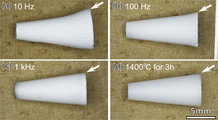
In contrast, as shown in Figs. 6(c) and (e), the use of an AC electric field greatly reduces the inhomogeneity observed in the shrinkage under a DC electric field. However, the uniformity depends on the frequency used. At the low frequency of 10 Hz, the cracks and deformation of the sintered compact are reduced, as seen for the DC field; however, the cross-section of the sintered compact shown in Fig. 6(d) still shows contrasting thin blackened regions extending from the two electrodes. These regions are caused by the electrode overvoltage effect, which is more pronounced at lower frequencies. As in the case of the DC electric field, there is a clear difference in the amount of shrinkage between the blackened regions and regions without blackening. The region indicated by arrow A, where the amount of shrinkage is smaller, is considered to still be affected by densification due to heat conduction from the region where electric power was effectively applied (arrow B). In contrast, when the frequency is increased to 1 kHz, as shown in Fig. 6(e) and (f), the blackening inside the sintered compact disappears and the densification progresses uniformly. Figure 7 shows the results of flash sintering under the same conditions as Fig. 6.32) The shapes at the bottom of the cone, as indicated by the white arrows in the respective figures, begin to resemble the structures obtained by thermal sintering (sintering without an electric field) as the frequency increases. A frequency of 1 kHz exhibits uniform densification comparable to that of thermally sintered compacts. The results of Figs. 6 and 7 demonstrate the importance of using a high-frequency AC electric field in flash sintering.

Using an electric field with alternating polarity, such as an AC waveform, is also effective in BaTiO3. To suppress the formation of oxygen vacancies caused by the reduction effect of a DC electric field, it is particularly effective to use a square wave with alternating polarity that includes a field-free duration, as shown in Fig. 8(b).36) In the case of BaTiO3, where sufficient densification was originally impossible because of electric discharge, this electric field waveform does not cause electric discharge, as shown in Fig. 8(a). A sintered compact of BaTiO3 with a white color (meaning no discharge) can be obtained, indicating that it is an electrical insulator. No amorphous layer or second phase is observed at the grain boundaries.

As described above, a high-frequency AC electric field is essential for the flash sintering (voltage-to-current) method. However, care must also be taken to avoid overshooting caused by the sample electric current exceeding the current limit preset in the power supply. The magnitude of the overshoot depends on the controllability of the power supply. In the case of an AC electric field, the polarity of the electric field is always alternating, so the controllability of the power supply is significantly decreased for rapidly increasing electric currents (i.e., electric current spike). When using AC electric fields, the controllability of the power supply plays an important role in obtaining a sintered compact with a uniform microstructure.
5. Importance of Power Spike Control
As mentioned above, the use of an AC electric field is necessary for flash sintering. However, the following issues remain, even when AC electric fields are used. Figure 9 shows the grain structure inside and near the surface of the 3YSZ flash-sintered compact produced using a 1 kHz AC electric field. Coarsening of the grains is observed inside the sintered compact, which may be caused by the uneven distribution of heat inside the sintered compact that occurs during flash events.37) The temperature of the sintered compact is roughly determined by a balance between Joule heating due to electric power input and blackbody radiation dissipated from the surface.11,38,39) Because the flash event occurs in an instant, Joule heating tends to be unevenly distributed inside the sintered compact, resulting in the coarsening of grains inside the sintered compact. This phenomenon is considered unavoidable in the voltage-to-current method.

Figure 10 shows the process time dependence of the relative density during flash sintering for 8YSZ using an AC electric field, in which flash sintering was maintained for approximately 1 h in Stage III after the occurrence of a flash event. Although a flash event occurs and a large densification occurs (process time = 0 min), no further densification is observed in the steady state afterward (a red line). The cessation of densification is an important result that appears to be overlooked in related studies. Figure 11(b) shows the internal microstructure of the flash-sintered compact, which is a porous microstructure corresponding to a low relative density, as presented in Fig. 10. However, considering the microstructure in the vicinity of the surface, as shown in Fig. 11(c), only a region of approximately 20 µm from the surface is found to be densified. In this region, the residual pore diameter and pore density are significantly decreased. In other words, only the surface area is preferentially densified, and a characteristic microstructure is formed in which the thin densified area surrounds the porous sintered compact. This preferential surface densification strongly suppresses internal densification. Even after holding the compact in Stage III for a long time, the grain size and pore size only increase inside the sintered compact, and no densification progress is observed, as confirmed in Fig. 10 (red line).40) Although the cause of the preferential densification at the outer periphery remains unclear, it may be due to the temperature distribution between the surface and the interior that occurs during the furnace heating regime. Green compacts are generally heated in a furnace until a flash event occurs. Because the heating is due to the heat radiation from the heater of a furnace, the temperature of the outer periphery of the compact is expected to be higher than that of the interior, and this temperature difference results in a difference in electrical conductivity, which is similar to the chain of events described above regarding thermal runaway. This uneven distribution of electric power to the surface is considered to be one of the causes of preferential densification.


Although instantaneous densification by the voltage-to-current method is attractive, further improvement as the flash sintering method is necessary because it limits the uniformity of grain structure and the final density. The most important factor is adequately controlling the power spikes that occur too rapidly during the flash event; in the voltage-to-current method, the electric current value increases sharply up to the electric current limit set in Stage I. Specifically, it is necessary to develop a method to control the electric current spikes that occur during Stage II. To suppress power spikes, it is sufficient to control the electric current value at this stage. For example, the multi-step method37) increases the current limit in steps, and the current-ramp method41–43) varies the current value as a linear, square, square-1/2, or logarithmic function with respect to time. In these methods, steep power spikes are suppressed, and the achieved density and grain structure uniformity are improved. Recently, Kuma et al. improved the current-ramp method further and reported that uniform grain structure can be obtained even under a DC electric field.25) They call it the current-rate method, implying that the current value is appropriately increased linearly with time.
To consider flash sintering as one of the more practical sintering technologies, a method is required that can provide a more general form of the compact (not a dog-bone shape), and in the case of zirconia ceramics, a method that can increase the density to a level that can guarantee useful mechanical properties. The author conceived the idea of applying current limiting control to the linear shrinkage rate.44,45) This method is called the shrinkage-rate controlled flash (SCF) method, which is introduced in the next section.
6. Shrinkage-Rate Controlled Flash (SCF) Sintering
The basic concept of the SCF method is similar to the rate-controlled sintering (RCS) method that has been previously used in thermal sintering.46,47) The RCS method controls the heating rate of a furnace so that the linear shrinkage rate is constant. The SCF method, however, adjusts the linear shrinkage rate by controlling the electric power input to the green compact. The basic concept of both methods is similar, but the SCF method can enable densification speeds that cannot be achieved using the RCS method because of direct heat using electric power input to green compacts.
Figure 12 shows the time evolution of the linear shrinkage in the SCF method and variation in parameters, such as electric current density, when controlling the linear shrinkage rate.48) In the SCF method, a constant electric field is applied while the current limit is initially set to a low value to suppress the steep current spike during a flash event, in which the power supply is driven in a constant-voltage control mode. At the flash temperature, the sample electric current reaches this low current limit. At this point, the power supply switches to a constant-current control mode. Thereafter, as shown in Fig. 12(a), the current limit is increased in small increments so that the linear shrinkage rate remains constant. The basic process of SCF control involves increasing the current value to a set maximum value while repeating the flash event in small increments, as shown in Fig. 12(b). It does not matter whether the sintering state of the green compact is in FAST or Stage II at the start of the SCF control. As shown in Fig. 12(b), the power density, current density, and electric field in the linear shrinkage rate control section (SCF section) change at each control time (Δt). The current density repeats cycles of increasing and maintaining constant values at every Δt. The electric field strength shows a spike-like change, increasing sharply with the increase in electric current and then decreasing. This behavior is like that of a small flash event in the voltage-to-current method described in Fig. 2. In other words, the SCF method repeats small-scale flash events at every Δt.

Figure 13 shows the time evolution of linear shrinkage and electric power dissipation during SCF sintering of 8YSZ. The time shown on the horizontal axis is adjusted at the start of the SCF control section when the sample electric current reaches the initial electric current limit. The figure also shows the results of the voltage-to-current method under the same initial electric field (black line). First, conventional flash sintering exhibits the steep power spike shown in Fig. 13(b), and at the same time, significant densification occurs, as shown in Fig. 13(a). This is typical behavior of the voltage-to-current method. However, the densification that originally progressed at the flash temperature stops at approximately 21%. This phenomenon is similar to that described in Fig. 11. In contrast, the SCF method shows consistent linearity in the time dependence of the linear shrinkage rate under all conditions of the linear shrinkage rate. Thus, the linear shrinkage is appropriately controlled by regulating the limiting current value and is significantly higher than that obtained by the conventional flash sintering method. Controlling linear shrinkage is an effective method to increase density.

In the SCF method, a characteristic time dependence of the power density is observed. As shown in Fig. 13(b), the power density exhibits an inversed S-curve behavior, with an initial increase, a nearly constant slope, a large increase, and finally a constant time trend. The section where the power dissipation is constant corresponds to a steady state in which the current value in the SCF control section reaches a preset maximum current value and is then controlled under a constant-current value. Because the sample temperature can be considered to vary along the power dissipation transition shown in Fig. 13(b), the sample temperature during SCF control initially increases at a high rate, then at a lower rate, increases at a high rate again, and finally becomes constant. Such a time evolution of the sample temperature observed in SCF is similar to the temperature evolution in a furnace during the RCS method. The RCS method varies the temperature rise rate of a furnace so that the linear shrinkage rate of the compact remains constant. In thermal sintering using a constant heating rate, there are three main regions: a slow shrinkage rate in the early stage, a fast shrinkage rate in the middle stage, and a slow shrinkage rate in the last stage. This rate of shrinkage is fed back to a furnace to adjust the power to the furnace heaters to let shrinkage rate constant. The power transition to a furnace at this time is similar to the power dissipation transition observed in the SCF method. Although the basic concepts of the SCF and RCS methods are similar, the SCF method can heat the compact directly. In the RCS method, the temperature increase rate of a furnace cannot keep pace with the shrinkage rate, which drops significantly in the last stage of thermal sintering. In the case of the RCS method, the controllability of the RCS method deteriorates significantly as it approaches the later stages of sintering. Furthermore, the time required for RCS is much longer than that for the SCF method. The SCF method is characterized by its ability to heat the compact directly using electric power and its high controllability.
Figure 14(a) shows the total power input for each SCF condition shown in Fig. 13 versus the linear shrinkage rate.48) The total power input is integrated only for the SCF control section (the steady-state section is excluded). The lower the controlled shrinkage rate, the longer the time required to reach the final density, and thus the higher the total power input. Figure 14(b) shows the total power input for Fig. 14(a) versus the inverse of the linear shrinkage rate. The power input during conventional flash sintering performed under the same initial electric field is also shown in the figure (red triangle). The total power input in the SCF method has a linear dependence on the inverse of the linear shrinkage rate. In this plot, the higher the linear shrinkage rate, the smaller the value on the horizontal axis. In other words, this linear dependence indicates that the total power input decreases as the linear shrinkage rate increases. Notably, the extrapolation of this linear dependence roughly corresponds to the total power obtained during conventional flash sintering. In other words, the conventional flash sintering method can be considered an excellent energy-saving sintering process.

Figure 15 shows the results of SCF sintering performed for 3YSZ. A controllable linear shrinkage rate and a high shrinkage rate are also realized in 3YSZ, like 8YSZ shown in Fig. 13. The Y2O3 content of 3YSZ is located in the two-phase region consisting of tetragonal and cubic phases at the sintering temperature. Therefore, during the sintering process, the Y concentration increases at or near the grain boundary because of this phase separation. The Y segregation of approximately 6 mol% occurs at grain boundaries at approximately 1300°C, and the formation of a cubic phase starting from the grain boundary has been reported at 1500°C.49) Figure 15(c) shows the results from the compositional analysis of 3YSZ sintered under SCF sintering at 100 V/cm. As shown in the figure, Y content is distributed in the range of approximately 4.5 to 8.5 mol% at the grain boundaries; however, this value is much smaller than the Y segregation observed in thermally sintered compacts. This may be related to the reduction in the time required for the densification process during SCF sintering.

As mentioned above, one of the characteristics of flash sintering is a short time scale. In this sense, although the shrinkage and microstructure are more uniform for the SCF method than for the voltage-to-current method, there is still room for improvement in terms of densification time. Therefore, an attempt was made to shorten the entire sintering process, including the temperature rise time to the onset of the SCF control section.50) Here, considering the amount of shrinkage of the green compact in the SCF control section, as shown in Figs. 13(a) and 15(b), the linear shrinkage of the green compact increases from approximately 0% to 22%. This means that almost all of the shrinkage occurs only in this SCF control section. This time is approximately 20 min for a rate of 300 µm/min, as shown in Fig. 13(a). Figure 16 shows the initial attempts to shorten the total sintering time using the SCF method. First, note that the sintering process shown in Fig. 16 is completed in approximately 40 min, including the temperature ramp process up to the onset of the SCF control section. The density of the sintered compact produced by this rapid SCF-sintering method is approximately 6.05 g/cm3, which is almost the same as the density of the thermally sintered compact (6.06 g/cm3 at 1400°C × 3 h). Figure 17 shows the Vickers hardness and fracture toughness of the sintered compact produced by this rapid SCF method. The mechanical properties of the rapid SCF-sintered compact are almost the same as those of the thermally sintered compact shown in the comparison. Despite the short sintering time of approximately 40 min in the no-pressure sintering process, the sintered compacts exhibit a high density near the theoretical density as well as mechanical properties similar to those of conventional sintered compacts.

7. Summary
In this paper, recent progress in flash sintering from the viewpoint of practical sintering application, that was performed by the author’s research group, has been reviewed, with a focus on the selection of electric fields to realize uniform shrinkage and grained structure. Furthermore, SCF method, that controls the electric power input while adjusting the linear shrinkage rate to a constant value, was proposed as one of the improved flash sintering techniques. The flash sintering method is not only a very interesting new sintering technique, but also a research field to explore new physical phenomena induced under electric fields. The author hopes that fascinating phenomena occurring under electric fields will be elucidated in the near future.
Finally, some of the research described in this paper was financially supported by the Japan Science and Technology Agency (JST) through the Adaptable and Seamless Technology Transfer Program (A-STEP: JPMJTS1617) and Core Research for Evolutional Science and Technology (CREST: JPMJCR1996), and MEXT through the Grant-in-Aid for Scientific Research (JP19H05788).
REFERENCES
- 1) C.C. Garrard: Nature 67 (1902) 67–68. doi:10.1038/067067a0
- 2) K. Terauds, J.M. Lebrun, H.H. Lee, T.Y. Jeon, S.H. Lee, J.H. Je and R. Raj: J. Eur. Ceram. Soc. 35 (2015) 3195–3199. doi:10.1016/j.jeurceramsoc.2015.03.040
- 3) M. Cologna and R. Raj: J. Am. Ceram. Soc. 93 (2010) 3556–3559. doi:10.1111/j.1551-2916.2010.04089.x
- 4) M. Yu, S. Grasso, R. Mckinnon, T. Saunders and M.J. Reece: Adv. Appl. Ceramics 116 (2017) 24–60. doi:10.1080/17436753.2016.1251051
- 5) M. Biesuz and V.M. Sglavo: J. Eur. Ceram. Soc. 39 (2019) 115–143. doi:10.1016/j.jeurceramsoc.2018.08.048
- 6) O. Guillon, R.A. De Souza, T.P. Mishra and W. Rheinheimer: MRS Bull. 46 (2021) 52–58. doi:10.1557/s43577-020-00008-w
- 7) R. Raj, A. Kulkarni, J.M. Lebrun and S. Jha: MRS Bull. 46 (2021) 36–43. doi:10.1557/s43577-020-00011-1
- 8) T. Yamamoto, T. Kobayashi and H. Yoshida: J. Jpn. Soc. Poweder Powder Metallurgy 65 (2018) 646–653. doi:10.2497/jjspm.65.646
- 9) T. Yamamoto and H. Yoshida: Materia 57 (2018) 373–380. doi:10.2320/materia.57.373
- 10) H. Yoshida and T. Yamamoto: J. Jpn. Soc. Poweder Powder Metallurgy 64 (2017) 523–531. doi:10.2497/jjspm.64.523
- 11) R.I. Todd, E. Zapata-Solvas, R.S. Bonilla, T. Sneddon and P.R. Wilshaw: J. Eur. Ceram. Soc. 35 (2015) 1865–1877. doi:10.1016/j.jeurceramsoc.2014.12.022
- 12) J.M. Lebrun and R. Raj: J. Am. Ceram. Soc. 97 (2014) 2427–2430. doi:10.1111/jace.13130
- 13) J.M. Lebrun, T.G. Morrissey, J.S.C. Francis, K.C. Seymour, W.M. Kriven and R. Raj: J. Am. Ceram. Soc. 98 (2015) 1493–1497. doi:10.1111/jace.13476
- 14) J.M. Lebrun, C.S. Hellberg, S.K. Jha, W.M. Kriven, A. Steveson, K.C. Seymour, N. Bernstein, S.C. Erwin and R. Raj: J. Am. Ceram. Soc. 100 (2017) 4965–4970. doi:10.1111/jace.15071
- 15) J.M. Lebrun, S.K. Jha, S.J. McCormack, W.M. Kriven and R. Raj: J. Am. Ceram. Soc. 99 (2016) 3429–3434. doi:10.1111/jace.14326
- 16) H. Charalambous, S.K. Jha, J.S. Okasinski and T. Tsakalakos: Scr. Mater. 190 (2021) 22–26. doi:10.1016/j.scriptamat.2020.08.026
- 17) Y. Yamashita, T. Kurachi, T. Tokunaga, Y. Yoshida and T. Yamamoto: J. Eur. Ceram. Soc. 40 (2020) 2072–2076. doi:10.1016/j.jeurceramsoc.2019.12.060
- 18) K. Nambu, H. Hayasaka, T. Yamamoto and H. Yoshida: Appl. Phys. Express 12 (2019) 075504. doi:10.7567/1882-0786/ab2b6e
- 19) A. Itoh, T. Tokunaga, A. Kodaira, H. Yoshida and T. Yamamoto: Ceram. Int. 48 (2022) 28712–28717. doi:10.1016/j.ceramint.2022.06.185
- 20) J.S.C. Francis and R. Raj: J. Am. Ceram. Soc. 96 (2013) 2754–2758. doi:10.1111/jace.12472
- 21) K.S. Naik, V.M. Sglavo and R. Raj: J. Eur. Ceram. Soc. 34 (2014) 4063–4067. doi:10.1016/j.jeurceramsoc.2014.04.043
- 22) R. Kirchheim: Acta Mater. 175 (2019) 361–375. doi:10.1016/j.actamat.2019.06.030
- 23) S.K. Jha, K. Terauds, J.M. Lebrun and R. Raj: J. Ceram. Soc. 124 (2016) 283–288. doi:10.2109/jcersj2.15248
- 24) F. Yoshida, Y. Sakka, T. Yamamoto, J.M. Lebrun and R. Raj: J. Eur. Ceram. Soc. 34 (2014) 991–1000. doi:10.1016/j.jeurceramsoc.2013.10.031
- 25) P. Kumar M K, D. Yadav, J.M. Lebrun and R. Raj: J. Am. Ceram. Soc. 102 (2019) 823–835. doi:10.1111/jace.16037
- 26) N. Morisaki, H. Yoshida, K. Matsui, T. Tokunaga, K. Sasaki and T. Yamamoto: Appl. Phys. Lett. 109 (2016) 083104. doi:10.1063/1.4961624
- 27) N. Morisaki, H. Yoshida, T. Kobayashi, T. Tokunaga and T. Yamamoto: J. Am. Ceram. Soc. 101 (2018) 3282–3287. doi:10.1111/jace.15485
- 28) T. Kurachi, Y. Yamashita, T. Tokunaga, H. Yoshida and T. Yamamoto: J. Am. Ceram. Soc. 103 (2020) 3002–3007. doi:10.1111/jace.16990
- 29) N. Morisaki, T. Tokunaga, K. Kobayashi, A. Kodaira and T. Yamamoto: Ceram. Int. 48 (2022) 12091–12097. doi:10.1016/j.ceramint.2022.01.069
- 30) H. Yoshida, A. Uehashi, T. Tokunaga, K. Sasaki and T. Yamamoto: J. Ceram. Soc. Jpn. 124 (2016) 388–392. doi:10.2109/jcersj2.15259
- 31) J.C. M’Peko, J.S.C. Francis and R. Raj: J. Eur. Ceram. Soc. 34 (2014) 3655–3660. doi:10.1016/j.jeurceramsoc.2014.04.041
- 32) T. Kurachi, K. Kobayashi, T. Tokunaga and T. Yamamoto: J. Jpn. Soc. Powder Powder Metallurgy 68 (2021) 487–493. doi:10.2497/jjspm.68.487
- 33) M. Biesuz, L. Pinter, T. Saunders, M. Reece, J. Binner, V.M. Sglavo and S. Grasso: Materials 11 (2018) 1214. doi:10.3390/ma11071214
- 34) R.E.W. Casselton: J. Appl. Electrochem. 4 (1974) 25–48. doi:10.1007/BF00615903
- 35) D.A. Wright, J.S. Thorp, A. Aypar and H.P. Buckley: J. Mater. Sci. 8 (1973) 876–882. doi:10.1007/BF02397918
- 36) R. Umemura, T. Tokunaga and T. Yamamoto: J. Ceram. Soc. Jpn. 128 (2020) 1018–1023. doi:10.2109/jcersj2.20181
- 37) J.V. Campos, I.R. Lavagnini, R.V. de Sousa, J.A. Ferreira and E.M.D.A. Pallone: J. Eur. Ceram. Soc. 39 (2019) 531–538. doi:10.1016/j.jeurceramsoc.2018.09.002
- 38) R. Raj: J. Eur. Ceram. Soc. 32 (2012) 2293–2301. doi:10.1016/j.jeurceramsoc.2012.02.030
- 39) R. Raj: J. Am. Ceram. Soc. 99 (2016) 3226–3232. doi:10.1111/jace.14178
- 40) M. Seko, K. Hattori, Y. Ishino, A. Kodaira, T. Tokunaga and T. Yamamoto: J. Ceram. Soc. Jpn. 130 (2022) 895–898. doi:10.2109/jcersj2.22109
- 41) K.H. Christian, H. Charalambous, S.K. Jha and T. Tsakalakos: J. Eur. Ceram. Soc. 40 (2020) 436–443. doi:10.1016/j.jeurceramsoc.2019.09.036
- 42) T.P. Mishra, R.R.I. Neto, R. Raj, O. Guillon and M. Bram: Acta Mater. 189 (2020) 145–153. doi:10.1016/j.actamat.2020.02.036
- 43) C.A. Grimley, S. Funni, C. Green and E.C. Dickey: J. Eur. Ceram. Soc. 41 (2021) 2807–2817. doi:10.1016/j.jeurceramsoc.2020.11.040
- 44) K. Taguchi, Y. Ishino, T. Tokunaga and T. Yamamoto: J. Eur. Ceram. Soc. 41 (2021) 4567–4571. doi:10.1016/j.jeurceramsoc.2021.03.005
- 45) Y. Ishino, K. Taguchi, M. Koike, T. Tokunaga and T. Yamamoto: J. Am. Ceram. Soc. 104 (2021) 4960–4967. doi:10.1111/jace.17912
- 46) M.L. Huckabee and H. Palmour, III: Am. Ceram. Soc. Bull. 51 (1972) 574–576.
- 47) O. Abe: J. Ceram. Soc. Jpn. 100 (1992) 1196–1199. doi:10.2109/jcersj.100.1196
- 48) Y. Ishino, T. Kimihiro, A. Kodaira, T. Tokunaga and T. Yamamoto: J. Jpn. Soc. Powder Powder Metal. 68 (2021) 482–486. doi:10.2497/jjspm.68.482
- 49) K. Matsui, H. Horikoshi, N. Ohmichi and M. Ohgai: J. Am. Ceram. Soc. 86 (2003) 1401–1408. doi:10.1111/j.1151-2916.2003.tb03483.x
- 50) Y. Ishino, K. Taguchi, A. Kodaira, T. Tokunaga and T. Yamamoto: J. Ceram. Soc. Jpn. 129 (2021) 551–554. doi:10.2109/jcersj2.21066