The Award of The Electrochemical Society of Japan (Takei Award), 2021
Developments in New Materials for Electrochemistry and Energy Storage Devices

2023 年 91 巻 10 号 p. 102001

詳細
2023 年 91 巻 10 号 p. 102001
The development of new materials leads to the invention of new devices. The exploitation of high ionic conductivity materials has facilitated the emergence of a new category of energy storage devices, including the all-solid-state battery. This paper reviews the history of the development of lithium solid electrolytes and their application in all-solid-state batteries. Particular focus is given to the development process of Li10GeP2S12, which surpasses the conductivity characteristics of liquid-electrolyte systems targeted by lithium-ion conductors, and its application to solid-state batteries is described. Furthermore, this review describes new science that will be born when batteries become solid-state.
Rechargeable batteries convert electrical energy into chemical energy, store it, and convert it back to electrical energy for reuse. Over the past 200 years of battery development, new devices have rarely emerged in the industry. Introduced in 1991, lithium-ion batteries (LIBs) have groundbreaking performance and are still evolving. Therefore, research aimed at creating new electrochemical materials and contributing to the development of novel energy storage devices faces numerous hurdles. The performance limitations of rechargeable batteries are primarily determined by their material properties, necessitating the development of novel materials with superior characteristics. In the pursuit of diligently understanding the phenomenon of ion diffusion within solids, exploring new substances via research and attempting their application in batteries have enabled the successful exploration of lithium-based systems, and the goal of producing battery solids is finally beginning to yield results. The history and current state of research on solid-state batteries, which have not yet been recognized as rechargeable batteries, are discussed in this paper. Particular focus is given to the attempts and setbacks of pioneering studies that sought to connect new materials with solid-state batteries, fortunate examples that progressed from material discovery to actual battery development, and the band structure of batteries, which are envisioned as a new frontier in science.
A solid formed by ionic bonding contains ions that diffuse at the approximate melting point. Ion diffusion in solids is usually extremely slow, as compared with that in liquids, but rare cases exist in which ions exhibit fast diffusion in certain solids. Such materials are called “ionic conductors.” Similar to liquids, the phenomenon of ions moving within a lattice formed by strong chemical bonds is intriguing. Such solids are also referred to as solid electrolytes, ionic conductors, fast ionic conductors, or super-ionic conductors, and various researchers have used terminologies associated with the history of their research. This review uses the “solid electrolytes” and “ionic conductors” terms. Funke1 and Yamamoto2 provided remarkable insights into solid-state ionics. Ions suitable for diffusion within solids have small ionic radii and low valence, such as H+, H−, Li+, F−, Na+, K+, Cu+, Ag+, O2−, and Mg2+. In particular, monovalent ions exhibit rapid diffusion. Material exploration has progressed with AgI as the starting point for silver and copper compounds. In the 1970s, compounds such as RbAg4I5 and Rb4Cu16I7Cl13 were discovered to achieve high conductivity, which exceeded 0.1 S cm−1 at room temperature.
An application of ionic conductors is in solid-state batteries. Silver and copper solid-state batteries have shown excellent charge-discharge and high current characteristics, but have a low energy density, which makes them impractical. Therefore, the development of lithium-based solid electrolytes and solid-state batteries has progressed significantly. However, lithium solid-state batteries pose challenges concerning the ionic conductivity of their electrolyte, which is approximately 10−4 S cm−1, and face issues with the potential window, preventing them from achieving full-scale product development. Ionic conductors that can be used as electrolytes play a crucial role in the development of solid-state batteries.
2.2 Lithium-ion conductivityThe ionic conductivities of electrolytes used in batteries are related to their current characteristics. Aqueous electrolytes have high conductivity and are used in batteries, such as lead-acid batteries and dry manganese cells, which employ a bulk structure for electrodes. The electrodes in LIBs using organic solvent-based electrolytes with conductivities of approximately two orders of magnitude lower have a thin-film structure that reduces the internal resistance. The magnitude of the electrolyte resistance not only affects the charging and discharging currents but also influences the battery structure. Upon examining the Arrhenius plot of the ionic conductors (Fig. 1), the following classifications were made according to their conductivity values: (1) Highest conductivity group: aqueous electrolytes, and copper and silver solid electrolytes, which have conductivity above 10−1 S cm−1 at room temperature. (2) Group with ionic conductivity exceeding 10−2 S cm−1 at room temperature: crystalline sulfides (Li10GeP2S12 (LGPS),3 argyrodite,4,5 and Li7P3S116,7), lithium battery electrolytes, and ionic liquids. In liquid systems, the ion transference number is approximately 0.5, whereas it is 1 in solid systems, indicating a significant advantage of solid-state systems. (3) Group with ionic conductivity ranging from approximately 10−3 to 10−4 S cm−1 at room temperature: amorphous sulfide systems, crystalline halide systems, and crystalline oxide systems. (4) Groups with low ionic conductivities: dry polymer and amorphous oxide systems. Owing to their advantageous characteristics, such as moldability and electrochemical stability, they are used in battery designs such as thin-film and flexible rechargeable batteries.
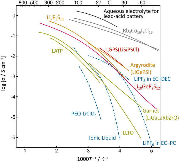
Arrhenius plots of the ionic conductivity for various ionic conductors.
In the 1980s, researchers conducting exploratory studies on silver and copper-based solid electrolytes shifted their focus to lithium-based solid electrolytes, marking the beginning of research in this field.8 Materials such as Li3N, LISICON (Li2+2xZn1−xGeO4-based materials), and NASICON (Na3Zr2PSi2O12-based materials) appear promising, and research has been conducted to vary their compositions and structures based on their basic frameworks. This has resulted in the accumulation of vast amounts of data and information that have been documented in solid-state chemistry textbooks and are common knowledge. However, these materials have not been used in devices because of their low electrochemical stabilities. Therefore, taking a step beyond materials research and finding a pathway for device applications are universal challenges. Although materials with high ionic conductivity have been developed, and without discussing battery characteristics, attempts to apply these materials to solid-state batteries have rarely resulted in improved performance. Therefore, the development of solid-state battery technologies must be investigated. Table 1 summarizes the typical crystalline lithium-ionic conductors. Figure 2 illustrates the structures of the major lithium-ion conductors. Various conductive materials with high ionic conductivities have been synthesized, and their applications in solid-state batteries have been attempted. However, these attempts have not led to the successful development of batteries with the most conclusive research and development in this area. These intriguing materials represent an excellent research example for exploring the transition from material exploration to practical device applications.
| Structure type | Chemical composition system | Composition | Conductivity at room temperature, σ/mS cm−1 |
References |
|---|---|---|---|---|
| LGPS | Li–M–P–S–X (M = Ge, Si, Sn; X = Cl, O) |
Li10GeP2S12 | 12 | 3 |
| Li9.54Si1.74P1.44S11.7Cl0.3 | 25 | 51 | ||
| Li9.42Si1.02P2.1S9.96O2.04 | 0.32 | 52 | ||
| Argyrodite | Li–M–P–S–X (M = Si, Ge; X = Cl, Br, I) |
Li6PS5Cl | 1.9 | 4, 5 |
| Li6.6Ge0.6P0.4S5I | 18.4 | 53 | ||
| Li7Ge3PS12 | 0.11 | 54 | ||
| Thio-LISICON | Li–M′–M′′–S | Li4.275Ge0.61Ga0.25S4 | 6.5 × 10⁻² | 55 |
| Li3.25Ge0.25P0.75S4 | 2.2 | 56 | ||
| β-Li3PS4 | 0.16 | 57 | ||
| Li7P3S11 | Li–P–S | Li7P3S11 | 17 | 6, 7 |
| Garnet | Li–La–M′–M′′–O (M′, M′′ = Zr, Nb, Ta, Ga, Ba, etc.) |
Li6BaLa2Ta2O12 | 0.4 | 58 |
| Li6.8La3(Zr1.8Nb0.2)O12 | 0.8 | 59 | ||
| Perovskite | Li–M–Ti–O (M = Ti, Nd) | Li0.34La0.51TiO2.94 | 1 (Single crystal) | 30 |
| NASICON | Li–M′–M′′–P–O (M′, M′′ = Al, Ti) |
Li1.3Al0.3Ti1.7(PO4)3 | 0.7 | 60 |
| LISICON | Li–M′–M′′–O (M′, M′′ = P, Si, Ge, Zn, and Ga) |
Li3.5Si0.5P0.5O4 | 2 (300 °C) | 61 |
| LiTa2PO8 | LiTa2PO8 | LiTa2PO8 | 1.6 | 42 |
| Complex Hydride | Li(CB9H10)–Li(CB11H12) | Li(CB9H10)–Li(CB11H12) | 6.7 | 48 |
| Halides | Spinel | Li2MgCl4 | 10−3 | 43 |
| Spinel | Li2Sc2/3Cl4 | 1.5 | 45 | |
| UCl3-type | Li0.388Ta0.238La0.475Cl3 | 3.2 | 47 | |
| Oxy-halides | LiTaOCl4 | LiTaOCl4 | 12.4 | 46 |
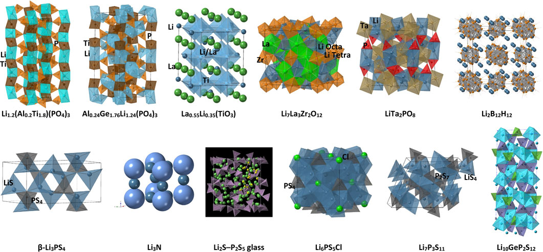
Structures of various ionic conductors: LATP (Li1.2(Al0.2Ti1.8)(PO4)3), LAGPA (La0.24Ge1.76Li1.24(PO4)3), perovskite (La0.55Li0.35(TiO3)), garnet (Li7La3Zr2O12), Li8TaPO6, closo-type complex hydrides (Li2B12H12), thio-LISICON-type β-Li3PS4, Li3N, Li2S – P2S5 glass,62 argyrodite-type (Li6PS5Cl), Li7P3S11, and LGPS-type (Li10GeP2S12).
High ionic conductivities were first reported by Huggins et al. in 1976.9 Powdered materials exhibit an ionic conductivity of 2.0 × 10⁻⁴ S cm−1 at 25 °C,10 whereas single crystals with a layered structure have an ionic conductivity of 2 × 10⁻³ S cm−1 in the vertical direction.11 These values were the highest until the discovery of the crystalline sulfide thio-LISICON in 2000. The active research conducted in the past was discussed in a review by Huggins.10 Li3N exhibits high ionic conductivity owing to the presence of impurities and defects generated during its synthesis. N-Li-N bridges are formed through lithium atoms between the layers of Li3N, allowing lithium to diffuse within the two-dimensional tunnels. The potential window is narrow, causing a reaction with positive electrode materials that possess a potential of 1.74 V or higher, relative to Li/Li+. Composite systems with improved characteristics have been investigated, with the binary systems of Li3N and lithium halides mainly being explored in Japan. For example, various intermediate compounds with inverse fluorite-type structures are present in the Li3N-LiCl system.12 Furthermore, derivatives, such as Li3AlN2, have been extensively reported.13 Therefore, high expectations for Li3N derivatives have been highlighted. However, none of the derivatives were able to sufficiently improve the conductivity and potential window, preventing them from becoming mainstream solid electrolytes.
3.1.2 LiPONBates et al.14 synthesized LiPON using high-frequency magnetron sputtering in a nitrogen environment, targeting Li3PO4. This amorphous thin film incorporated nitrogen and exhibited a conductivity of 2 × 10⁻⁶ S cm−1 at 25 °C. Reducing the thickness of the electrolyte film can decrease battery resistance in thin-film batteries. Thin-film solid-state batteries created by depositing LiCoO2, LiPON, and lithium from the vapor phase demonstrate excellent charge-discharge characteristics.15,16 Owing to the 0–5.5 V potential window with respect to Li/Li+, LiPON allows the use of a wide range of electrode materials, making it a mainstream electrolyte for thin-film batteries. However, the deployment of thin-film batteries faces challenges in determining their application.
3.1.3 LISICONIn 1972, West17 reported an ionic conductivity of 3 × 10⁻⁴ S cm−1 at 300 °C in Li4SiO4 and Li4Si0.6Ti0.4O4, based on the Li3PO4 structure. In 1978, Hong18 reported an ionic conductivity of 0.1 S cm−1 at 300 °C in Li14Zn(GeO4)4. Numerous related substances, such as LISICON, also exist. Molecular dynamic (MD) calculations demonstrated that Li4Al1/3Si1/6Ge1/6P1/3O4 exhibits a conductivity of 0.8 mS cm−1 due to the mixed polyanion effect.19 Mixed systems have achieved ionic conductivities of 10−4 S cm−1 (at room temperature) in germanium-, vanadium-, and gallium-based compositions.20 Thereafter, the characteristics of solid-state batteries using LISICON as the electrolyte have been consistently reported.21
3.1.4 NASICONIn 1976, Goodenough et al.22 reported Na1+xZr2SixP3−xO12 (x ≈ 2) to have a conductivity of 5 S cm−1 at 300 °C. Since then, various substances have been reported to exchange Na+ with ions such as Li+, Ag+, and K+. The structures of these materials include a three-dimensional framework, where MO6 octahedra and PO4 tetrahedra share corners, and two different sites within the gaps of the structure are occupied by Na+ or Li+ ions, which move through the bottleneck regions. LATP and LAGP exhibit high conductivities of 5 mS cm−1.23,24 Solid-state batteries have been constructed using methods such as the sol-gel method25,26 and screen printing.27 The advantages of solid-state batteries have been realized by stacking single cells of the rocking-chair-type Li3V2(PO4)3/Li1.5Al0.5Ge1,5(PO4)3/Li3V2(PO4)3.27 Furthermore, their application in practical chip-type batteries is under development. Therefore, an excellent example of constructing a superior solid-state battery using electrode and electrolyte materials within a reasonable potential range was used, and sintering expertise to build a stacked structure was leveraged.
3.1.5 PerovskiteIn 1984, Latie et al.28 and Kochergina et al.29 reported LixM1/3Nb1−xTixO3 (M = La, Nd) and Li0.5La0.5TiO3, respectively. Thereafter, Inaguma et al.30 demonstrated a conductivity of 1 × 10⁻³ S cm−1 at 25 °C for Li0.34La0.5TiO2.94 in 1993. Further insights were provided by Stramares et al.31 in a review article. Li3xLa(2/3)−x(1/3)−2xTiO3 exists in the cubic, tetragonal, and orthorhombic crystal phases, with the cubic phase exhibiting higher conductivity. Ionic conduction is correlated with the order-disorder arrangement of lithium and lanthanum vacancies along the c-axis. Although the ionic conductivity within the grains exhibit values exceeding 10−3 S cm−1, the presence of grain boundary resistance and the reducibility of titanium imposes challenges on the use of lithium metal as a negative electrode. Attempts are underway to substitute titanium in the structure with stable elements. Although research on solid-state batteries is limited, attempts have been made to achieve a stacked configuration using the rocking chair-type method with electrolytes having honeycomb or 3DOM structures.32
3.1.6 GarnetThe first garnet-type oxide containing lithium with the general formula Li5La3M2O12 (M = Ta, Nb) was synthesized by Hayashi et al.33 in 1986. Weppner discovered its high ionic conductivity, wide potential window (approximately 6 V vs. Li), and stable operation using lithium metal as the negative electrode.34 The ionic conductivity range was 10−5–10−3 S cm−1. The garnet structure follows the general formula C3A2B3O12, where the C, A, and B sites are 12-, 8-, and 4-coordinated with oxygen, respectively. In Li5La3Ta2O12, lithium partially occupies the normally vacant octahedral (48 g) and tetrahedral positions (24d). Garnet-type oxides are a mainstream topic in oxide-type solid-state battery research and numerous review articles have been published on the subject.35 Various battery configurations have been reported, including attempts to create all-solid-state batteries by sintering oxide electrodes and electrolytes together, and using composite electrodes that incorporate polymers, ionic liquids, or electrolytes immersed between the solid electrolyte and the electrode. The former approach enables battery operation through low-temperature sintering or innovative sintering methods,36 whereas the latter approach faces challenges such as the formation of lithium dendrites causing short circuits during charge-discharge cycling. The introduction of liquid electrolytes or other components can enhance the charge-discharge performance of lithium-ion batteries and improve their safety. However, achieving the expected improvements in battery performance when transitioning from a liquid to a solid-state electrolyte system is challenging.
3.1.7 Inverse perovskite structures and glass electrolytesIn 2012, the inverse perovskite structures of Li3OCl and Li3OCl0.5Br0.5 were reported to exhibit ionic conductivities of 8.5 × 10⁻⁴ and 1.94 × 10⁻³ S cm−1 at room temperature, respectively.37 The A, B, and X sites in the perovskite structure (general formula ABX3) are occupied by halogens, oxygen, and lithium, respectively. The presence of defects leads to the emergence of ionic conductivity,38 but the removal of impurities, such as hydroxide ion (OH−), reduces the conductivity to 1.0 × 10⁻⁶ S cm−1 at room temperature.39 Glass electrolytes synthesized from the crystalline compositions of inverse perovskite compounds, such as Li3−2xBaxClO (x = 0.005), exhibit an ionic conductivity of 2.5 × 10⁻² S cm−1 at room temperature and have been explored in solid-state battery research.40,41 Their reported ion conductivities are exceptionally high and have gained considerable attention. However, these materials exhibit high hygroscopicity and present challenges in their evaluation as battery systems.
3.1.8 LiTa2PO8A bulk conductivity of 1.6 × 10⁻³ S cm−1 and total conductivity of 2.5 × 10⁻⁴ S cm−1 at 25 °C were reported in 2018. These values were obtained for a material in which the TaO6 octahedra and PO4 tetrahedra were connected through corner-sharing, forming a (TaO6/2)2(PO4/2) framework that provided pathways for lithium-ion conduction.42
3.1.9 HalidesIn 1981, spinel-type Li2MCl4 (M: Mg and Cd) was reported to exhibit an ionic conductivity of approximately 10−5 S cm−1 at room temperature; however, development in this area of study is limited.43 Compounds such as Li3ErCl6, Li3YCl6, Li3InCl6, and Li3−xM1−xZrxCl6 (M = Er, Y) (1.4 mS cm−1) and spinel-type Li2Sc2/3Cl4 (1.5 mS cm−1) have recently been reported.44,45 Halides are stable at high potentials and enable the battery characteristics of layered rocksalt-type cathode materials to emerge without the need for coating materials. Although advantages are offered in terms of ionic conductivity owing to the monovalent valence of the anion, which weakens the Coulombic force with lithium, material diversity is limited, making material exploration challenging. However, active exploration in this field is underway.46,47
3.1.10 Closo-type complex hydridesCloso-type (caged) complex hydrides [Mx(My′Hz), where M represents a metal cation and My′Hz represents a complex anion] have been reported to exhibit high lithium ionic conductivity. The Li(CB9H10)–Li(CB11H12) quasi-binary system was reported to exhibit a conductivity of 6.7 × 10⁻³ S cm−1 (room temperature).48,49 In addition, the stability offered by these materials to lithium metal and their solid-state battery characteristics have been reported, thus leveraging flexibility.50 Therefore, these materials are promising electrolytes for electrode composites.
3.2 Approaches to solid sulfide electrolytesVarious crystalline electrolytes have been developed since the development of glass-based sulfides, including thio-LISICON, LGPS, argyrodite, and Li7P3S11.
3.2.1 Sulfide glass systemsIn the 1970s, glass-based sulfides were initially explored using silver and copper systems, which then expanded to lithium-based systems, leading to the discovery of a series of Li2S-P2S5-based glasses.63 Li2S-P2S5-LiI system glasses (with Li2S/P2S5 = 2) exhibit a high conductivity of approximately 10−3 S cm−1 at 25 °C. Research on solid-state batteries using M2S-GeS2-MI (M = Li, Ag) glass electrolytes has been primarily conducted in France.64 However, solid electrolytes composed of Li2S, SiS2, GeS2, LiI, and other similar constituents exhibit limited electrochemical stabilities, hindering the development of solid-state batteries. Kondo et al.65 reported a significant improvement in electrochemical stability using a glass electrolyte composition of 0.03Li3PO4-0.59Li2S-0.38SiS2, exhibiting a conductivity of 6.9 × 10⁻⁴ S cm−1. Extensive research has subsequently been conducted on batteries using this glass electrolyte. The energy density of solid-state batteries was enhanced with the use of 4 V positive electrodes,66,67 and challenges, such as self-discharge and cycle characteristics, were improved. Furthermore, batteries employing graphite as a negative electrode were reported,68 leading to the realization of lithium-ion-type solid-state batteries.69
3.2.2 ArgyroditeLi6PS5X (X = Cl, Br, I) compounds based on the basic structure of argyrodite (Ag8GeS6) were reported in 2008.4 Li6PS5X (X = Cl, Br, I) adopts the same crystal structure as the cubic copper- and silver-argyrodite compounds. Lithium ions are randomly distributed in the tetrahedral positions (48 h and 24 g sites), whereas phosphorus and sulfur occupy the tetrahedral positions (4b site) and 16e site, respectively, forming isolated PS4 tetrahedra that extend in three dimensions. Additionally, the X ions form a face-centered cubic lattice (4a and 4c sites). The lithium ions diffuse through partially occupied positions. Li6PS5I exhibits lower ionic conductivity than Li6PS5Cl and Li6PS5Br. The introduction of defects increases the ionic conductivity, and defective argyrodite Li6−xPS5−xCl1+x exhibits a high ionic conductivity of 17 mS cm−1.70 Solid-state batteries employing argyrodite-type sulfides (Li6PS5X, X = Cl, Br) were reported in 2010,71 and significant progress has been made in subsequent technological developments.
3.2.3 Li7P3S11Li7P3S11 was reported during the synthesis of a Li2S-P2S5 glass system. After ball milling, Li7P3S11 underwent crystallization through heat treatment, exhibiting an ionic conductivity of 3.2 × 10⁻³ S cm−1 at room temperature.72 Subsequently, a value of 1.7 × 10⁻² S cm−1 at room temperature was determined.7 The structure of the material was similar to that of Ag7P3S11, where the PS4 tetrahedra are connected through corner sharing, forming a framework structure consisting of P2S7 units.73 This is distinctive, as compared to other LiPS-based materials, in which the PS4 tetrahedra exist in an isolated form. Challenges regarding stability, as compared to PS4 units, exist. Within the Li2S-P2S5 system, various compounds, including Li2P2S6, Li4P2S6, Li7P3S11, α-Li3PS4, β-Li3PS4, γ-Li3PS4, LT-Li7PS6, and HT-Li7PS6, are available, which can be categorized based on the arrangement pattern of the PS4 tetrahedra.74
3.3 Development of early solid-state sulfide batteriesBattery development using glass-based sulfide electrolytes began in the mid-1990s. However, in 2000, crystalline thio-LISICON emerged to expand the types of available solid electrolytes. Sulfide electrolytes are soft and have low grain boundary resistance.75 Similar to silver and copper solid-state batteries, bulk-type batteries can be easily constructed by pressing the three-layer structure of the negative electrode/electrolyte/positive electrode together. Additionally, methods for interface control have progressed. Takada et al.76 reported an improved interface stability by coating Li4Ti5O12 onto LiCoO2 surfaces, enabling fast charging and discharging. Currently, coating with LiNbO2 is essential for stabilizing solid-state batteries. A self-formed interface, called the SEI layer, is generated between the negative electrode and solid electrolyte through electrical conduction, promoting interaction and close contact between them. The concept of SEI formation can also be applied to solid-state batteries.77
In the 2000s, technological developments with a focus on battery manufacturing processes, including electrode sheets and electrolytes, were initiated. Positive electrode sheets with current-collect grids, electrolyte sheets with mechanical support, and freestanding electrolyte sheets have been developed. Batteries composed of aluminum/lithium composite sheet negative electrodes have also been developed,78 and dry and wet manufacturing methods for electrolyte sheets using binders, such as liquid silicone, styrene-butadiene copolymer, and silicone rubber, have been investigated.79 Manufacturing processes have been developed for practical applications, including screen printing and transfer methods for sheet formation. However, the performance achieved was not comparable to that of liquid-electrolyte-based batteries and attempts to create actual battery prototypes at the time were unsuccessful. The importance of solid electrolytes with a performance equivalent to that of liquid electrolytes used for lithium-ion batteries and the identification of challenges and solutions at the electrode-electrolyte interface in practical batteries have led to the recognition of the issues to be addressed and pave the way for the next step.
The process that led to the discovery of lithium-ion conductors (LGPS) is discussed in this section. In the 1980s, silver solid-state batteries were reported to have excellent long-term storage characteristics for approximately 30 years,80–82 whereas copper solid-state batteries were found to be suitable for rocking-chair-type batteries, offering reliability and high-speed charge-discharge capabilities.83 However, these batteries exhibit fatal flaws that prevent their practical use as high-energy-density batteries. Based on this experience, Kondo et al. initiated pioneering research by introducing network-forming materials into lithium sulfide-based glasses to synthesize electrochemically stable electrolytes and operate batteries. In response to these efforts, the exploration of sulfide glass-based solid electrolytes has progressed, led by researchers such as Minami at Osaka Prefecture University, who established glass systems as mainstream lithium-ion conductors.
4.2 Thio-LISICON system developmentDuring the 1990s, crystalline materials were believed to not exhibit ionic conductivities as high as those of glassy materials. In this situation, crystalline thio-LISICON was found to have higher ionic conductivities than the glassy materials. The choice between glass and crystals was based on whether the framework structure of the material is disrupted to facilitate rapid ion diffusion or construct pathways that are as ordered as possible. The low conductivity of the crystalline systems led to the belief that the exploration of materials was insufficient, prompting further investigation. A comprehensive exploration of composite anion systems comprising nitrides, phosphides, halides, and sulfides was conducted to identify the composition regions with high ionic conductivity. Regions with relatively high ionic conductivities were observed in the sulfide system. This approach involved selecting sulfide as the end component and systematically exploring the compositions based on the phase diagrams of the three-component systems. This method is similar to the conventional approach used in glass research for investigating glass-forming regions. The method of exploring ternary phase diagrams in crystalline materials is not commonly employed, but Takahashi and Yamamoto et al. used this approach in their research on copper-ion conductors.84 In the initially chosen three-component system of Li2S-Ga2S3-GeS2, similarities with existing LISICON were observed during the indexing of X-ray diffraction patterns of the composition region with high conductivity, indicating the presence of ionic conductors in sulfide systems possessing crystal structures similar to oxide systems.55 Furthermore, the existence of a group of materials named “thio-LISICON,” which refers to sulfide-based LISICON compounds (Fig. 3), was revealed. In particular, Li4GeS4-Li3PS4 pseudo-binary system exhibits high ionic conductivities.56 These materials represent the first instances in powder form with ion conductivities exceeding 10−3 S cm−1 at room temperature. However, attempts to create functional prototypes of practical batteries were not successful.
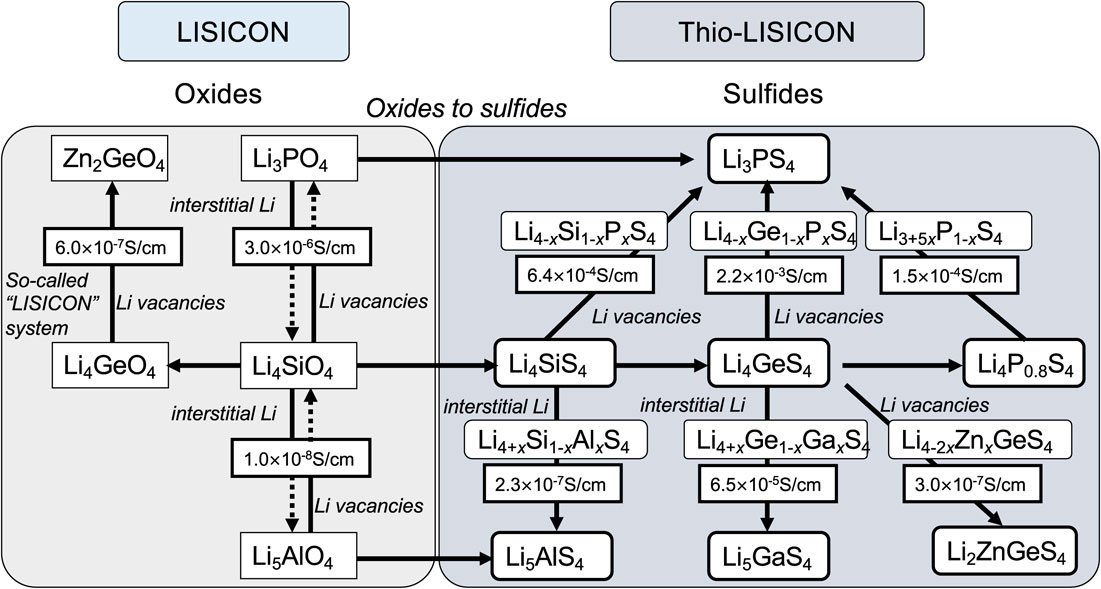
LISICON and thio-LISICON substance correlation chart.56
Pulverization is necessary to create submicron particles for using solid electrolytes as electrode materials. The crystallinity decreases and the particle surface is affected by moisture during the grinding process, leading to a decrease in conductivity. In thio-LISICON, the discovery of LGPS was triggered by the observation that the conductivity did not decrease under certain grinding conditions. While examining the phase diagram of the Li4GeS4-Li3PS4 binary system to determine the region of thio-LISICON formation, grinding was speculated to induce a transition from a LISICON compound structure to a different crystal structure. The phase newly formed through mechanochemical reactions was expected to exhibit high ionic conductivity. This phase was named as the “X-phase” within our research group, and experiments were conducted to achieve a single-phase structure by varying the composition and reaction conditions. In conclusion, a single-phase structure was obtained when the synthesis was performed by adhering to the basics of solid-phase reactions, such as repeating the solid-phase reaction by friction and high-temperature calcination to complete the reaction. The synthesis involved simple mixing of the starting materials and calcination. The ionic conductivity exceeded 10−2 S cm−1,3 which surpasses the conductivity characteristics of liquid-electrolyte systems targeted by lithium-ion conductors; this value was achieved within a decade of achieving conductivity in the range of 10−3 for thio-LISICON. The space group was determined using synchrotron X-ray diffraction data from Spring 8, and structural analysis using ab initio methods was conducted. Fortunately, the parent structure was solved, and the positions of the lithium atoms were determined using the Rietveld method with neutron diffraction data collected from a high-resolution powder diffractometer (J-PARC). Its structure is illustrated in Fig. 4. Within the three-dimensional framework structure, lithium ions, which are mobile, are distributed in the tunnels of the conductive pathway, and this structure is suitable for the rapid diffusion of ions. A structural analysis indicated that the composition was Li10GeP2S12.

Structure of LGPS:3 framework structure and ionic conduction paths.
GeS4 and PS4 tetrahedra and LiS6 octahedra share edges to form chains that extend one-dimensionally along the c-axis of the tetragonal lattice, and the PS4 tetrahedron binds to a one-dimensional chain by sharing corners to form a three-dimensional framework. Two types of lithium positions (Li1 and Li3) exist within the one-dimensional tunnel. The Li1 position is split into two centers within the octahedron. The lithium occupancy rates at positions Li1 and Li3 are approximately 0.5, indicating a continuous distribution of lithium along the one-dimensional chains. The Li2 position is located within the one-dimensional chain of the framework and has an occupancy rate of 1; however, it does not contribute to ion diffusion. The six-coordinate octahedron (Li4) is another lithium position that exists between the one-dimensional chains of lithium and forms a two-dimensional plane with the neighboring lithium chains. The anisotropy of the thermal vibration parameters of Li1 and Li3 and the average distribution of Li suggest the existence of one-dimensional diffusion along the c-axis and a two-dimensional diffusion pathway through Li4. Figure 5 shows the battery characteristics of the first solid-state cell using LGPS. The charge-discharge curve appears typical of LIBs, but if the curve represents the characteristics of a solid-state cell, then a solid-state system can exhibit properties similar to those of a liquid system.

Characteristics of solid-state batteries using a LiCoO2 cathode, Li10GeP2S12 electrolyte, and indium anode.3
After the discovery of LGPS, immediate verification using computational science and elemental substitution was conducted. Adams et al. identified the Li4 position and highlighted two-dimensional diffusion through the identified position.85 Ceder et al. received significant attention for demonstrating a pioneering prediction of material properties, such as conductivity and electrochemical stability, through elemental substitution with silicon and tin.86 However, the challenge of using electrolytes as practical materials is their diversity. Their repertoire has been established through elemental substitution, resulting in a variety of materials. Table 2 lists examples of LGPS-type ion conductors selected based on their high ionic conductivity, electrochemical stability (potential window), and chemical stability, which make them suitable for solid-state batteries. Examples include Si-Sn solid-solution systems without germanium, Li-P-S systems with enhanced electrochemical stabilities, oxide-ion additive systems with enhanced chemical stabilities, and halogen-based systems with excellent ionic conductivities. For example, Li9.54Si1.74P1.44S11.7Cl0.3 exhibits a conductivity of 25 mS cm−1 at room temperature, whereas LGPS containing only LiPS enhances the electrochemical stability.51 A conductivity exceeding 10−2 S cm−1 was also achieved in the Si-Sn system,87 and the addition of oxide or antimony ions improved the electrochemical and chemical stabilities. Additionally, materials, such as halogen-substituted systems that form a stable interface with lithium metal and silicon-based materials, that further enhance the ionic conductivity are available.88,89 More recently, a LGPS-derivative with a conductivity of 32 mS cm−1 has been synthesized by a high-entropy approach.90
| Composition | σRT/S cm−1 | Ea/eV | Temperature range T/K |
References |
|---|---|---|---|---|
| Li9.54Si1.74P1.44S11.7Cl0.3 | 2.5 × 10⁻² | 0.26 | 243–298 | 51 |
| Li10(Si0.5Ge0.5)P2S12 | 4.2 × 10⁻³ | 0.29 | 243–298 | 91 |
| Li10(Ge0.5Sn0.5)P2S12 | 6.0 × 10⁻³ | 0.28 | 243–298 | 91 |
| Li10(Si0.5Sn0.5)P2S12 | 4.3 × 10⁻³ | 0.31 | 243–298 | 91 |
| Li10GeP2S11.7O0.3 | 1.2 × 10⁻² | 0.18 | 298–398 | 92 |
| Li9.6P3S12 | 1.2 × 10⁻³ | 0.36 | 173–253 | 51 |
| 0.24 | 253–373 | |||
| Li9P3S9O3 | 4.3 × 10⁻⁵ | 0.35 | 298–473 | 93 |
| Li10GeP2S12 | 1.2 × 10⁻² | 0.31 | 193–298 | 3 |
| 0.17 | 322–673 | |||
| Li10.35Si1.35P1.65S12 | 6.7 × 10⁻³ | 0.30 | 173–298 | 94 |
| 0.14 | 322–673 | |||
| Li9.81Sn0.81P2.19S12 | 5.5 × 10⁻³ | 0.29 | 173–298 | 94 |
| 0.19 | 322–573 | |||
| Li9.42Si1.02P2.1S9.96O2.04 | 1.0 × 10⁻⁴ | 0.27 | 298–523 | 52 |
| Li10GeP2S12 single crystal [110] | 7.0 × 10⁻³ | 0.34 | 243–293 | 95 |
| 0.43 | 200–243 | |||
| Li10GeP2S12 single crystal [001] | 2.8 × 10⁻² | 0.33 | 243–293 | 95 |
| 0.40 | 200–243 | |||
| Li10GeP2S12 | 7.6 × 10⁻³ | 0.27 | 233–333 | 96 |
| Li10Ge2/3Sn1/3P2S12 | 6.4 × 10⁻³ | 0.28 | 233–333 | 96 |
| Li10Ge1/3Sn2/3P2S12 | 4.8 × 10⁻³ | 0.28 | 233–333 | 96 |
| Li10SnP2S12 | 3.8 × 10⁻³ | 0.30 | 233–333 | 96 |
| Li10GeP2S12 grain | 1.0 × 10⁻² | 0.32 | 143–213 | 97 |
| Li10GeP2S12 powder | 9.5 × 10⁻³ | 0.32 | 143–333 | 97 |
| Li10(Si0.3Sn0.7)P2S12 | 7.6 × 10⁻³ | 0.30 | 143–333 | 97 |
| Li10SnP2S12 | 5.6 × 10⁻³ | 0.32 | 143–333 | 98 |
| Li10.35[Sn0.27Si1.08]P1.65S12 | 1.2 × 10⁻² | 0.19 | 298–393 | 87 |
| Li9.54Si1.74P1.44S11.7−zCl0.3Oz (z = 0.3), LSiPSClOz (0 < z ≤ 0.6) | 2.8 × 10⁻² | 0.16 | 175–233 | 88 |
| Li10P3S12Br | 5.8 × 10⁻³ | 0.17 | 230–300 | 89 |
| Li10.25P3S12.25I0.75 | 9.1 × 10⁻³ | 0.17 | 230–300 | 89 |
| Li9.54[Si0.6Ge0.4]1.74P1.44S11.1Br0.3O0.6 | 3.2 × 10⁻² | 0.24 | 230–300 | 90 |
The discovery of the solid electrolyte LGPS has triggered rapid advancements in the research and development of solid-state batteries. The advantages of solidifying batteries include (1) the ability to operate over a wide temperature range, simplifying the cooling system; (2) improved volume efficiency of battery systems through bipolar stacking, leading to increased energy density at the battery pack level; and (3) use of the high ionic conductivity (transference number = 1) of the solid electrolyte, enabling high current capabilities during battery reactions. In liquid electrolytes, both cations and anions move towards opposite sides, whereas in solid-state batteries, only lithium ions transport charge. A concentration gradient that limits diffusion in liquid electrolytes does not occur in solid-state batteries, which is advantageous for electrochemical systems. Solid-state batteries are less restricted by the chemical diffusion of lithium, enabling high currents and thicker electrodes. Therefore, the possibilities for high-power, fast-charging, and high-energy-density single cells arise with the potential for improvements in both energy and power densities.
Kato et al. were the first to demonstrate the unique characteristics of LGPS-based solid-state batteries.51 Standard batteries were created using the LGPS electrolyte and a LiCoO2 cathode. High-power batteries were created using Li9.54Si1.74P1.44S11.7Cl0.3 as the electrolyte with the highest ionic conductivity and Li4Ti5O12 as the anode. High-energy density batteries were created using a carbon anode and Li3.2PS4 with a wide potential window. These batteries exhibited high-output characteristics, operated in the temperature range of −30–100 °C, and demonstrated excellent charge/discharge reversibility and unique properties that were previously unattainable in solid-state batteries. The output characteristics surpassed those of capacitors, and the advantages of solid-state energy storage in terms of high current density during charging and discharging were revealed for the first time. Figure 6 shows a Ragone plot, where a higher output (vertical axis) and energy density (horizontal axis) indicate superior device performance. Solid-state batteries offer advantages in terms of output characteristics and energy densities. Furthermore, the operation of thick-film electrodes (600 µm cathode layer) was confirmed.99 Following these observations, research on solidifying energy-storage devices has progressed at an astonishing speed.
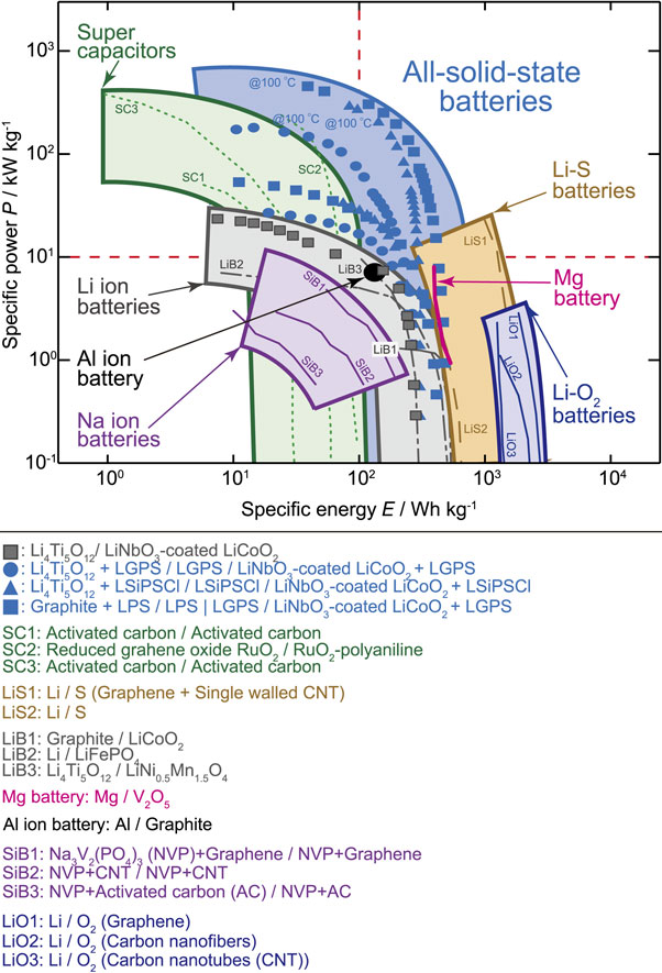
Ragone plots of various energy storage devices.51 The Ragone plot compares the energy and power densities. The data for each cell was normalized using the positive electrode weight.
Solid-state batteries, as compared to conventional battery systems, exhibit superior characteristics. However, several challenges have been identified in practical battery applications, which are discussed in this section. (1) Adhesiveness: The electrolyte in liquid-based batteries permeates the electrode composite to ensure ion conduction pathways, whereas in solid-state batteries, ion conduction pathways must be established in advance using a mixture of powders. (2) Interface stability: Additives are added to the electrolyte in LIBs to decompose and generate a SEI layer during charging and discharging, which allows for reversible electrode reactions. Surface-coated cathodes have been used in the solid-state systems.100 (3) Electrolyte-electrode combination: Different types of electrolytes can be used for the cathode, anode, and separator. High-ion-conducting materials are employed in the separator to reduce internal resistance, whereas electrolytes with corresponding potential windows are used on the anode and cathode sides. Although comprehensive details of the challenges have been omitted in this review, gradual development of solutions is expected as challenges become apparent.
The foundation of material exploration lies in the periodic table, which serves as a guiding principle for inorganic chemists who unconsciously use the information embedded within the table when selecting elements. The characteristics of the crystal structures also serve as criteria for judgment. Considering the features of ionic conductors, West’s textbook101 on solid-state chemistry states the following: (1) Conductors possess ion conduction pathways that can be one-, two-, or three-dimensional. (2) An optimal relationship exists between the size of the ions and the bottlenecks encountered during diffusion. (3) Ions forming diffusion pathways must be prone to distortion (high polarizability). (4) The mobile ions within the diffusion pathways preferentially occupy a partially occupied state. These are the necessary conditions for achieving fast ion diffusion, but they are not sufficient, which poses a challenge. Although electronic conductivity is undesirable for electrolytes, it is necessary for electrodes.
Material exploration methods can be classified as follows. (1) Exploration through element substitution: this method involves replacing the constituent elements of known materials with other elements. Almost all diverse systems, such as LGPS, perovskites, garnets, and LISICON, have been studied using this technique. (2) Exploration based on structure: this approach involves introducing the desired diffusing ions into existing crystal structures to create new materials. However, this approach can be challenging because it includes structures that do not contain conducting species. Furthermore, methods such as ion exchange have also been employed. The perovskite and garnet structures were initially discovered using this approach. (3) Composition-based exploration: although the likelihood of discovering materials is low, this approach holds the potential for the discovery of new materials. This method involves the selection of diffusing ion species and framework-forming elements, followed by exploration of materials within phase diagrams. This method relies heavily on the experience and intuition of researchers.
Thio-LISICON and LGPS were developed using composition-based exploration methods. The selection of elements requires lithium as an essential component, and the options for the corresponding anion to construct the crystal lattice include easily manageable oxygen or the more flexible (greater polarizability) sulfur. Selenium is not considered because of its metallic properties and toxicity. Halogens have a weak Coulombic interaction with lithium because of their monovalent nature, making lithium more mobile; however, they limit the selection of corresponding cations. Once the basic cations and anions are determined, the elements used to construct the crystal lattice are selected. Elements of rock-forming minerals, such as silicon and phosphorus, can be used as they forms suitable framework structures for ion conduction. Because ionic conductors require defects within their structures, the incorporation of elements with different valences is necessary. Therefore, germanium, in addition to lithium and sulfur, was chosen as the framework-forming element in the exploration of thio-LISICON, whereas gallium was used to vary the valences. This combination of elements was interpreted as a pseudo-ternary system of Li2S-GeS2-Ga2S3. Compositional mapping within the system was performed through synthesis experiments, which ultimately led to the discovery of the LISICON structures.
The real simulation of material exploration lies in the emergence of new groups of materials with favorable properties in regions with unexpected compositions. In various fields, the discovery of new materials with superior characteristics outside the known areas is often described as happening “by chance.” However, methods that have evolved throughout the long history of material exploration have led to discoveries through deliberate effort.
Based on the evolution of the existing exploration methods, it is possible to consider exploration methods in a virtual space. Techniques such as machine learning and interpolation make it difficult to discover new materials. Areas that encompass the potential for new materials must be defined to reach exploration areas beyond the scope of the existing materials. In experience- and intuition-based syntheses, researchers explore the entire range of the periodic table and selectively choose areas to focus on for synthesis based on their intuition. In particular, they empirically set up exploration areas that interpolate into unexplored territories, although this process is time-consuming. This trial-and-error approach has also been incorporated into approaches involving theoretical calculations, informatics, and data science, and is expected to progress further.
A battery is a device that separates two different substances (electrodes) using a membrane (electrolyte) and extracts the energy difference between the electrodes through an external circuit. Electrochemical reactions in batteries are complex, and a gap exists between the well-defined electrochemical interfaces established by aqueous electrolytes and metal electrodes and the description of actual battery reactions. In addition to the inherent differences in electrochemical reactions, when a battery transitions from a liquid to a solid system, the electronic states can be experimentally observed. This review introduces an approach to understand battery reactions by capturing the changes in the electronic levels of materials and heterogeneous interface electronic levels.
7.1 Electrochemical interfaceInterest in the reaction mechanisms of batteries has increased because understanding practical battery reactions from an electrochemical perspective is challenging. In LIBs, a correlation exists between the changes in the crystal structure and the charge-discharge characteristics of the electrodes, leading to a predominance of research on the crystal structure changes in electrodes. However, the starting point of battery reactions lies at the interface between the electrode and the electrolyte (the electrochemical interface), and the structural changes in this region are not yet fully understood. Therefore, researchers have focused on using model thin-film batteries with such as epitaxial electrodes to elucidate detailed structural changes at the interface. Over the past 20 years, surface diffraction and reflectometry techniques using X-rays and neutrons have been established to detect structural changes on the electrode and electrolyte sides, respectively. Research has progressed to the point where the previously challenging structural changes at the interface can be systematically understood.102,103 Although means to detect structural changes in the interior and at the interfaces of materials used in batteries have been developed, there is a significant gap between these observations and the electrochemical reactions that occur in batteries. Conversely, electronic structural changes in the electrode and electrolyte have not been thoroughly considered in relation to battery reactions. Despite being fundamental information for batteries, attempts at direct measurements have not been made, as liquid electrolyte-based batteries have been the focus of investigation.
7.2 Battery cell potentialIntercalation electrodes are typically semiconductors, where the electrolyte acts as an insulator and the electrode-electrolyte interface forms a semiconductor-semiconductor junction. In semiconductor devices, only electrons or holes move across junctions. However, in rechargeable batteries, ions with a significant mass diffuse through the interface along with electrons, resulting in dramatic changes in the internal composition, crystal structure, and electronic structure. Scrosati et al. studied the thermodynamic treatment of the electromotive force of intercalation electrodes.104 The battery voltage, also known as VOC, is determined from the difference in the chemical potential of lithium between the positive and negative electrodes (μ).
| \begin{equation} {-}e V_{\text{OC}} = \mu_{\text{Li,Cathode}} - \mu_{\text{Li,Anode}} \end{equation} | (1) |
The cell voltage can be chemically approximated by the difference between the oxidation and reduction potentials of Li+/Li at the negative electrode and the oxidation-reduction potential of the transition metal ions operating in the oxidized state of the positive electrode (such as Co4+/Co3+ in LiCoO2). Moreover, from a physical perspective, the cell voltage can also be related to the difference in the electrochemical potentials corresponding to the Fermi levels of electrons at the positive and negative electrodes. However, the difference in the chemical potential of lithium between the negative and positive electrodes can be expressed as the sum of the differences in the chemical potentials of both electrons (e-) and ions (Li+). Therefore, the discussion of the electrode potential limited to the Fermi level (chemical potential of electrons) is an approximation; however, in several cases, it provides reasonable accuracy.105
The interface electronic structure of batteries has been investigated using model cells with thin-film electrodes, nonaqueous electrolytes, or solid electrolytes.105,106 By performing XPS measurements while stacking LiCoO2 thin films on a solid electrolyte (LIPON) several nanometers apart, the electronic structure from the outermost surface of the electrode to its interior and band bending at the interface can be determined. The initial electrode-electrolyte interface can be observed using this technique; however, no information about the electrochemical processes during charge and discharge is available. When the battery transitions from the liquid to the solid state, the electrochemical reactions at the electric double layer are described as reactions occurring in the so-called space-charge or depletion regions. The LiNbO3 coating on the surface of cathode materials for improving the properties of solid-state sulfide batteries was triggered by research aimed at controlling the space-charge layer.107 Subsequent to the pioneering studies on the interfacial electronic structure of thin-film batteries, electronic structure simulations of solid-state batteries have been conducted,108 highlighting the importance of the electronic structure.109 Furthermore, changes in the band structure during charging and discharging of batteries using operand techniques is now possible.110
7.3 Elucidation of the electronic structure of batteries using solid-state batteriesA study considering a thin-film battery with a lithium-excess Li2MnO3 electrode, a glass-based LASGTP electrolyte, aluminum current collector, Li2MnO3 positive electrode, LASGTP electrolyte, Li3PO4 electrolyte/coating material, and lithium negative electrode was conducted.111 First, the band structures of the current collector, positive electrode, electrolyte, and negative electrode were determined with respect to vacuum. The Fermi level, VBM, and CBM in the vicinity of the valence band were determined using the combined data from UPS, LEET spectra, and LEIPS. The electronic structures of the constituent materials were organized with respect to the vacuum level (Fig. 7). Based on the energy levels near the valence band, the band changes at the interface during battery formation (semiconductor junction) can be inferred before the battery is constructed. Based on this information, it was concluded that there were changes in the energy levels of the valence band for each component and in the binding energies of the core levels of the elements constituting each component during charging and discharging.

Band edges and Fermi levels of the current collector (aluminum), cathode (Li2MnO3), electrolyte (LASGTP), coating material (Li3PO4), and anode (lithium). The vacuum level standard was used for organization. The WF, Eg, EA, and IP are also shown.111
The energies of the inner shells of each constituent element with respect to the Fermi level were observed using hard X-ray photoelectron spectroscopy. The electronic structures of both the electrode and electrolyte can be simultaneously observed by using an electrode with a thickness that allows X-ray penetration. The shifts in the binding energy during charging and discharging of elements can be attributed to (1) chemical shifts due to changes in the oxidation state of the elements, (2) potential changes experienced by the materials within the battery, and (3) variations in the position of the Fermi level within the bandgap. The first (1) factor can be analyzed using XPS information when discussing the conventional reaction mechanism, allowing discussion of the charging and discharging mechanisms based on the oxidation-state changes of elements such as oxygen and manganese. Therefore, the oxidation-reduction of oxygen occurs reversibly throughout the entire region. In systems with excess lithium, the expected degradation caused by oxygen evolution does not occur in solid-state systems, thereby contributing to the advantages of solid-state batteries. In lithium-excess systems using liquid electrolytes, decomposition of the electrolyte on the electrode surface promotes the supply of oxygen from within the electrode, thereby accelerating electrode decomposition. Factor (2) refers to the changes in binding energy influenced by the cell potential. When the measurements were conducted against the lithium negative electrode as the measurement ground, all binding energies were relative to the Fermi level of lithium. Conversely, changes in the binding energy of the aluminum current collector, which acts as the counter electrode, correspond to variations in the cell potential. The Fermi levels of the current collector and positive electrode are assumed to match; however, achieving an ohmic junction at the interface between the current collector and electrode is a challenge. Shifts in the binding energies of the constituent elements in the electrolyte are influenced by the potential of the electrolyte within the battery. Factor (3) refers to the impact on electrodes when used as semiconductors, where changes in the composition and structure during charging and discharging can affect the semiconductor properties (such as the transition from p-type to n-type). When a change in the relationship between the Fermi level and VBM occurs, the relationship between the VBM and the energy levels of the core electrons does not change significantly, as expected. Therefore, when observing the binding energies relative to the Fermi levels, large shifts were detected for all elements. In the case of the Li2MnO3 positive electrode, charging dramatically altered the relationship between the Fermi level and VBM (confirmed by spectra in the vicinity of the valence band), influencing the measured values of the binding energy for core electrons. By comprehensively discussing the observed changes in the electronic structure during operand measurements, such as chemical shifts associated with reactions and band structure variations near the valence band, along with the potential changes experienced by each component in the battery, the actual battery reactions can be elucidated. An example of this discussion is provided below.
Figure 8 shows the overall changes in the band structure of the battery during the initial charge and discharge processes, with the Fermi level of the negative lithium electrode serving as the reference. The positions of the Fermi level, VBM, and CBM of the electrode and electrolyte and the variations in the semiconductor characteristics of the positive electrode during charging and discharging are shown. Therefore, the first operand measurement example of the band structure of the battery is presented. The changes in the binding energy of each element are illustrated in Fig. 9, where Al, P, and Li and O correspond to the current collector, electrolyte, and electrodes, respectively. The changes in the binding energy of Al were aligned with the changes in the cell potential. The binding energy of P remained unchanged, indicating that the potential sensed by the electrolyte remained constant throughout the charge-discharge cycle. No peak broadening was observed, indicating the absence of potential distribution within the electrolyte. The initial charging process was classified into four stages. Step 1: In the early stages of slight charging from the initial state, the potential (battery voltage) of Al and binding energies of Li and O in the electrode changed. No significant changes were observed in the electronic structure of the positive electrode; however, the charging reaction progressed. Step 2: The binding energy of Al significantly changed, whereas those of Li and O remained unchanged. This corresponds to electronic structural changes (p-n transitions) in the vicinity of the valence band of the positive electrode. Step 3: Charging progressed continuously. The binding energy values did not change, but the intensity of the O2− peak decreased whereas that of O− increased, indicating the ongoing oxidation of oxygen. Step 4: Reversible changes in the binding energy occurred during charging to approximately 5 V and under subsequent open-circuit conditions. Charges of approximately 5 V accumulated at the electrode-electrolyte interface but did not contribute to lithium release.
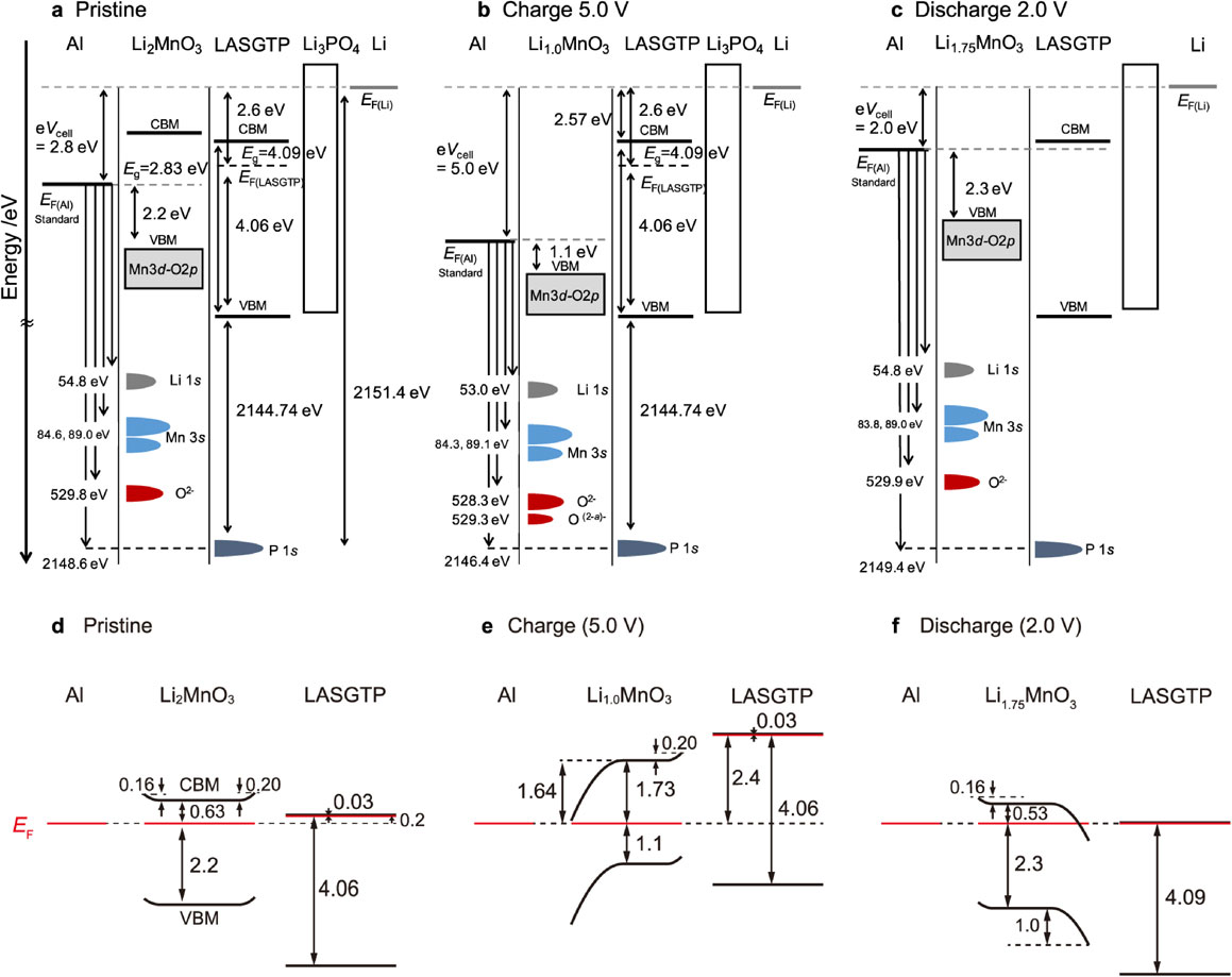
Changes in the band structure during charge-discharge cycling of an all-solid-state battery. (a, d) show the initial conditions, (b, e) present the initial charges at 5.0 V, (c, f) show the band diagrams of the battery during initial discharge at 2.0 V, and (d–f) show the predicted band bending on the cathode side.111

BE of operand hard X-ray photoemission spectroscopy with respect to the Fermi energy. The BE of each element was described with respect to the Fermi level of the anode (lithium). Because the BE shifts for each element during the initial charge, the shifts from the initial open-circuit voltage to a 5 V charge and the open-circuit voltage relaxation states are shown. Al reflects the cell voltage and chemical shifts of the current collector, Li and O reflect the electrode, and P reflects the potential and chemical shifts of the electrolyte.111
As previously mentioned, the electronic states of batteries during charging and discharging can be discussed based on experimental measurements. The interfacial junctions in solid-state batteries is challenging. Physical challenges in achieving adhesion and chemical challenges in ensuring stability have arisen. The latter has been addressed by developing coating materials that experimentally create stable interfaces, and thermodynamically stable interface phases have been predicted through calculations. However, electrochemical reactions associated with electron transfer are involved at actual interfaces, making it essential to understand their electronic structures. By gathering information on the electronic structures of the electrodes, coating materials, and electrolyte materials, a quantitative interface design can be achieved.
Solid-state batteries have gained recognition and are being developed as the next-generation battery technology. The transition from fundamental research to the next step is gratifying for researchers in this field. The foundation of solid-state batteries is expected to expand with the successful development of practical batteries. Conversely, the shift to solid-state batteries has opened new frontiers in battery science, leading to a deeper understanding of complex, fascinating, and useful battery reactions.
lithium-ion batteries
LGPSLi10GeP2S12
LISICONlithium superionic conductors (Li2+2xZn1−xGeO4-based materials)
NASICONNa-ion superionic conductors (Na3Zr2PSi2O12-based materials)
LiPONlithium phosphorus oxynitride
LATPLi1.2(Al0.2Ti1.8)(PO4)3
LAGPLi1.2(Al0.2Ti1.8)(PO4)3
3DOMthree-dimensionally ordered microporous
SEIsolid electrolyte interphase
VOCopen-circuit voltage
LASGTPLi1+x+yAlx(Ti,Ge)2−xSiyP3−yO12
VBMvalence band maximum
CMBconduction band minimum
UPSultraviolet photoelectron spectroscopy
LEETlow-energy electron transmission
LEIPSlow-energy inverse photoelectron spectroscopy
WFwork function
Egbandgap
EAelectron affinity
IPionization potential
BEbinding energy
The author would like to express sincere gratitude to all of the colleagues and students who have worked together with him in the course of his research on solid-state batteries.
Ryoji Kanno: Conceptualization (Lead)
The authors declare no conflict of interest in the manuscript.
R. Kanno: ECSJ Fellow

Ryoji Kanno (Institute Professor/Director, Research Center for All-Solid-State Battery, Institute of Innovative Research, Tokyo Institute of Technology)
Ryoji Kanno was born in 1956. He graduated from Graduate School of Science, Osaka University in March 1980, and earned Doctor of Science in 1984, He worked in Mie University (1980–1989) as Assistant Professor and in Kobe University (1989–2000) as Associate Professor. He moved to Tokyo Institute of Technology in 2000 as Professor. He was awarded Society award from The Electrochemical Society of Japan in 2021. His research interests are solid-state electrochemisty and battery. Hobby: Music.