1. Introduction
The size-selective separation of particles commonly called size classification or simply classification, which is one of the most important unit operations in powder technology. For controlling the particle size distribution or preparing nearly monodispersed materials dispersed in liquid, several techniques, such as hydraulic cyclone, elutriation, gravity separation, magnetic separation, screening, and sieving, have been proposed for the classification of particles and powders whose size is on the order of micrometers; these techniques enable control over particle size distribution and afford nearly monodisperse materials, which are required in several industrial applications (Masuda H. et al., 2006). Based on their principles, these techniques are classified into two categories; one involves the use of forces generated from external fields (i.e., gravitational, centrifugal, electrical, and magnetic), and the other involves the use of physical holes (i.e., sieving). Until now, the size classification techniques are still developing for sub-micrometer particles to enhance their properties.
The numerous characteristics of nanoparticles (NPs) can depend on their size and size distribution; for example, silicon NPs of size 2–16 nm have photoluminescence of wavelength 500–800 nm (Liu S.M. et al., 2006; Sugimoto H. et al., 2013). When particle size is controlled, NPs can be applied in sensors (Anker J.N. et al., 2008; Chan W.C.W. and Nie S., 1998; Klostranec J.M. and Chan W.C.W., 2006), drug carriers (Peer D. et al., 2007; Roy I. et al., 2003), super-capacitors (Nakanishi H. and Grzybowski B.A., 2010), diodes (Bliznyuk V. et al., 1999; Park J.H. et al., 2004), data storage media (Chon J.W.M. et al., 2007; Tseng R.J. et al., 2006), photocatalysis (Chin S. et al., 2011), or photonic (Barnes W.L. et al., 2003; Teranishi T. et al., 2005; Xie Z. et al., 2011) and photovoltaic (Hasobe T. et al., 2005; Sun B. et al., 2003) cells. Attempts have also been made to obtain novel materials through regular arrangement structure (e.g., colloidal crystal, and monoor multi-layer) of NPs. Several synthesis methods (Buck M.R. and Schaak R.E., 2013) have been proposed for the monodispersed or near-monodispersed NPs, which is essential. For example, reversed-micelle (Fontes Garcia A.M. et al., 2011; Mori Y. et al., 2001; Yang P. et al., 2011), hot-soap (De Mello Donega C. et al., 2005; Delalande M. et al., 2007; Murray C.B. et al., 1993), solvated metal atom dispersion (Cingarapu S. et al., 2009), and thermal decomposition methods (Murray C.B. et al., 1993), rapid expansion of supercritical solution (Vemavarapu C. et al., 2009), and synthesis in polymer gel (Sun Y. and Xia Y., 2002), clay gel (Arao Y. et al., 2009) or surface modification agent solution (Zhang H. et al., 2006) were applied to control NP size and shape.
Despite these techniques, similar to conventional precipitation methods used in NP preparation, additional classification procedures are often required for obtaining monodispersed NPs. In addition, purification of particles is required post-synthesis to remove byproducts. Therefore, size-selective separation as a post-synthesis operation is becoming increasingly important. In this review, recent developments in size-selective separation methods using external force fields, sieving and stability of colloidal systems are highlighted to focus NPs whose size is sub-micrometer, especially below several tens nanometer.
2. External force field
2.1 Field flow fractionation
Field flow fractionation (FFF), proposed by Giddings in 1966 (Giddings J.C., 1966), is a conventional method that employs several external force fields (Rübsam H. et al., 2012; Wahlund K.G., 2013). A field is considered effective if its strength and selectivity is sufficient to achieve separation (Messaud F.A. et al., 2009). Typical fields include cross-flow streams, temperature gradients, electrical potential gradients, centrifugal force, dielectrophoretic force, and magnetic force. These fields give rise to several FFF techniques, including flow (FlFFF), thermal (ThFFF), electrical (ElFFF), sedimentation (SdFFF), dielectrophoretic (DEP-FFF), and magnetic (MgFFF) field flow fractionation.
Fig. 1 shows the schematic of the separation principle of FFF and gives an overview of the experimental equipment (Mori Y., 1994). The separation occurs inside a narrow channel, in which the carrier solution flows as a laminar flow between the parallel walls. When an external field is applied perpendicular to the flow, i.e., x-axis, the particles concentrate at the accumulation wall. The formed concentration gradient induces particle diffusion in the reverse direction. After a certain period, the steady state concentration profile is reached; this profile depends on the chosen FFF method, that is, whether mass, electron charge, or magnetic property acts to make this profile. In case of SdFFF, that is, mass is the chosen property, heavier particles are located near the accumulation wall, while lighter particles are distributed near the center of the channel comparing with heavier particles. The average transport velocity of lighter particles is therefore higher than that of heavier particles because of the parabolic flow profile in the channel.
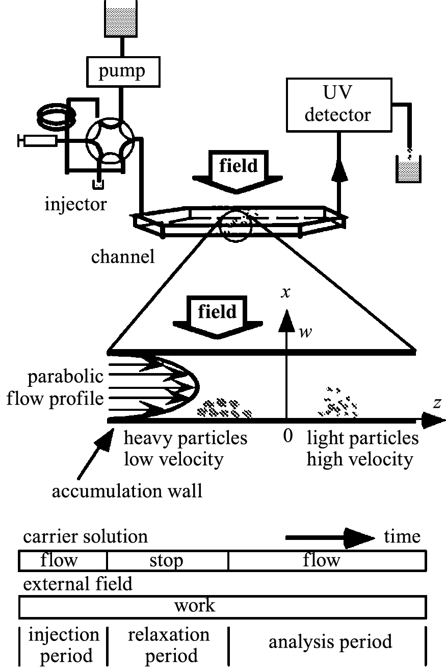
FFF operations usually proceed in three stages. The first stage is the injection period, where the sample is injected into the channel inlet under the external field. During the relaxation period, after stopping the carrier solution flow, the concentration profile starts to reach the steady state. In the analysis period, the carrier solution flows again. Particles move in the channel at different velocities under the external field.
Among these techniques, FlFFF, ThFFF, ElFFF, and MgFFF are currently available for NPs. Two types of FlFFF are currently used: symmetrical and asymmetrical (A4F). A4F is popular due to its commercial availability and has been employed in most recent research. For example, Hagendorfer et al. (Hagendorfer H. et al., 2011) demonstrated the fractionation of gold NPs of size 5–84 nm by using A4F. CdTe NPs were separated into relatively monodispersed fractions using ElFFF (Ho S. et al., 2009). Successful fractionation was evidenced by fluorescence spectra. The original sample with average diameter 4.7 nm had the maximum fluorescence peak at 615 nm. In the separated sample, red CdTe NPs fluoresced at 627 nm, which corresponds to a particle size of 5.1 nm, whereas the green fraction fluoresced at 564 nm, which corresponds to a particle size of 2.9 nm. For MgFFF, Latham et al. (Latham A.H. et al., 2005) used the capillary type and demonstrated that magnetic NPs can be separated according to not only size (6 and 13 nm) but also material composition (Fe2O3 and CoFe2O4).
2.2 Continuous field flow fractionation
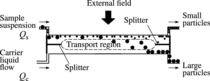
Although FFF has many variations and is used to separate particles of sizes ranging from a few nanometers to 100 μm, it is essentially a batch operation, and the amount of sample that can be processed at a time is very small (on the order of milligrams to micrograms). The development of new methods for continuous FFF of NPs is becoming more important in solving certain industrial problems. One such new method is split-flow thin fractionation (SPLITT) (Katasonova O.N. and Fedotov P.S., 2009).
Fig. 2 illustrates the principle of the SPLITT system. Fractionation is performed using a system of thin channels, each of which has splitters at the input and output within a separate column. The suspended particles and the pure carrier solution are simultaneously introduced into the column through the top and lower inlets, respectively. The flow velocity of the pure carrier solution is always higher than that of the sample suspension; therefore, the incoming particle stream is confined to a narrow layer in the upper portion of the column. Along with the carrier solution flow, the external force field perpendicular to the liquid flow also affects the particle movement in the channel. For example, when the external force field is gravity, large particles more rapidly settle under the effect of gravity and are collected from the lower outlet (Fig. 2). Smaller particles concentrating in the upper part of the channel is collected from the upper outlet. Thus, two particle fractions differing in size is obtained. The stability of both flows in the narrow channel is the critical parameter.
Contado et al. (Contado C. et al., 2000) the continuous separation of wheat starch particles using SPLITT and gravity as the external field. Because the dimensions of the system is relatively large, the sample size is over 1 μm. Under a 100 gravities field in the centrifuge of the SPLITT system, however, the magnetic particles in the sample, with size ranging from 60 to 1000 nm, were separated into two fractions at a cutoff size of 660 nm (Jiang Y. et al., 1999). Fuh and Chen (Fuh C.B. and Chen S.Y., 1999) reported the separation of magnetic particles by SPLITT applied magnetic field. They compared the horizontal setup of SPLITT with the vertical setup for separation efficiency. Magnetic and gravitational forces were used for separation in the horizontal setup, where the two forces were applied in opposite directions to facilitate separation; only magnetic force was applied in the vertical setup. They concluded that the horizontal setup was more effective than the vertical one for separation of magnetic particles with high densities and/or large diameters, because gravitational forces acting on particles tended to counteract the magnetic forces in the horizontal setup.
An electrical field also was applied to the SPLITT system. Narayanan et al. (Narayanan N. et al., 2006) designed a SPLITT system with various inlet, outlet, and splitter arrangements based on the simulation of two-dimensional computational fluid dynamics (Fluent commercial package). Excellent separation was achieved for a mixture of 108 nm and 220 nm amino-coated particles using the offset splitter model. Yamamoto et al. (Yamamoto T. et al., 2009; Yamamoto T. et al., 2011) classified silica particles using an electrical SPLITT system. Although the dimensions of their instrument was much larger than that of Narayanan et al. (Narayanan N. et al., 2006), cut-off size was between 45–80 nm depending on the experimental conditions, because the absolute value of zeta-potential increased with decreasing particle size, which assisted separation.
SPLITT affords continuous separation but has low throughput; further, there is difficult to find reports of its application to size-selective separation of NPs in the nm size ranges.
2.3 Centrifugal field
Use of centrifugal force is a common technique in size-selective particle separation. A hydrocyclone, where particles move toward the centrifugal field at different velocities depending on their size, is used for micrometer-size particles in a liquid system. The particle motion in the centrifugal field is described by following equation:
|
v
=
d
r
/
d
t
=
s
ω
2
r
, | (1) |
where
v is the particle settling velocity,
r is the distance from the axis of rotation,
t is time,
ω is angular velocity, and
s is the sedimentation coefficient. When the frictional coefficient is applied in the Stokes region,
s can be expressed as
|
s
=
x
2
(
ρ
p
−
ρ
f
)
/
(
18
η
)
, | (2) |
where
x is particle diameter,
ρp and
ρf are particle and liquid densities, respectively, and
η is viscosity of liquid. Nano-diamonds were separated by an ultracentrifuge according to the principle represented in
Eqn. (2) (
Morita Y. et al., 2008). On changing the rotation speed and application period, the average size of the particles in the upper solution (supernatant solution) was found to be controlled down to 4 nm using a 30 nm feed suspension size.
However, when particle size decreases to such a nanometer range, the Brownian motion of NPs becomes dominant, meaning that NPs cannot settle as described in Eq. (1). The diffusion (Brownian motion) of NPs was accounted for in the sedimentation behavior as follows (Fujita H., 1975):
|
(
∂
C
∂
t
)
r
=
−
1
r
∂
∂
r
{
s
ω
2
r
2
C
−
D
r
(
∂
C
∂
r
)
t
}
, | (3) |
where
C is particle concentration,
D is diffusion coefficient of NPs. The exact analytical solutions of this Lamm equation cannot be obtained, but currently numerical solutions can be obtained using several software programs (
Brautigam C.A., 2011;
Schuck P., 2010). The data measured by the analytical ultracentrifugation have been analyzed by these software programs to obtain the macro-molecular weight distribution of proteins (
Zhao H. et al., 2010) or the particle size distribution of ZrO
2 or SiO
2 (
Mittal V. et al., 2010). This effect of particle diffusion results poor separation if particle was small enough to apply
Eqn. (3). This means that more powerful techniques are required.
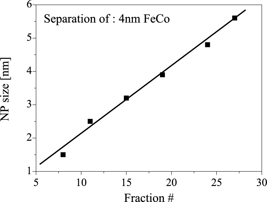
One successful technique, reported by Sun et al. (Sun X. et al., 2009), is the density gradient centrifugation (DGC) method. They used aqueous solutions with different concentrations of OptiPrepTM (60 % (w/v) iodixanol, 1.32 g·cm−3, Sigma-Aldrich, Inc.). Density gradient solutions of 10 %, 20 %, 30 %, and 40 % iodixanol were created directly in the centrifuge tubes, and a suspension of core(FeCo)–shell(C) NPs with average diameters of approximately 4 nm was placed on top of the density gradient solution. After centrifugation at approximately 240,000 g for 3.5 h, the sample was separated by size into 27 fractions. Fig. 3 shows the particle size of each fraction, which increased with fraction number (from top to bottom), measured by transmission electron microscopy. The size-selective separation from a gold NP mixture was also successfully performed in the same manner (Qiu P. and Mao C., 2011; Sun X. et al., 2009).
The separation mechanism of this DGC method can be understood by the difference of the apparent densities of NPs. For ideal spherical NPs with core density ρc, radius a, shell thickness of the capping agents or surface modification molecules δ, and apparent shell density (mixture of shell material and solvent molecules) ρs, the net density ρa can be estimated as
|
ρ
a
=
ρ
s
+
(
ρ
c
−
ρ
s
)
(
1
1
+
δ
/
a
)
3
. | (4) |
It can be deduced from Eqn. (4) that the net density of NPs would increase when the core size increases with respect to shell thickness, and the net density is equal to the core material density when the NPs are large enough. This means that small NPs would folate in a low-density solution and large NPs would settle to the bottom in a high-density solution using the DGC method. This method was proposed as one of the methods to prepare monodispersed silicon NPs from polydisperse alkyl-capped silicon NPs (Mastronardi M.L. et al., 2011).
The DGC method was also applied to the shape-selective separation of gold nanorods (11.5 ± 1.8 nm diameter, 36.9 ± 5.4 nm length) from a mixture with 24 nm diameter spherical gold NPs (Xiong B. et al., 2011). They calculated the force balance of a Brownian rod falling in a Stokes flow and introduced the quantitative dependency of the nanorod sedimentation rates on their mass and shape. Chen et al. (Chen G. et al., 2009) demonstrated the separation of dimers and trimmers of gold NPs covered with polystyrene-block-poly(acrylic acid) using this method.
The attempted continuous separation of NPs by centrifugal force was performed using a micro-channel (Kwon B.H. et al., 2013), which resulted in the reported separation of particles with a diameter of over 100 nm. This technique requires a great deal of effort for in the separation of NPs.
2.4 Electric field
Electrophoretic techniques can be used widely in biological and biochemical research to separate charged objects in a uniform electric field. In electric fields, charged molecules or particles migrate toward the electrode of opposite charge. The migration speed of a particle at steady state v is linearly proportional to the applied electric field strength E, as
where
μe is the electrophoretic mobility, which depends on the charge, size, and shape of particles. As a result, particles are ultimately separated into distinct bands in the electric field (
Zhu X. and Mason T.G., 2014). One of the most popular methods using the electrophoretic force is gel electrophoresis (GE) using agarose gel (AGE) or polyacrylamide gel (PAGE). The particles in GE migrate through a gel matrix. Because the drag force of particles from the gel matrix increases with particle size, GE can achieve excellent size separation.
Hanauer et al. (Hanauer M. et al., 2007) performed shape separation experiments with AGE using a mixture of spherical, triangular, and rod shaped gold or silver NPs. They found the mixture ratio of shape differed depending on gel position, but complete separation was not achieved. Wu et al. (Wu W. et al., 2013) reported the size and shape separation of gold NPs. They performed their first size separation using DGC and a subsequent shape separation using AGE. CdTe NPs were classified and purified by PAGE (Hlavacek A. and Skládal P., 2012). The separated fraction of CdTe NPs revealed narrower emission peaks (72 % of the original width) and improved quantum yield (two-fold).
2.5 Magnetic field
Magnetic field can separate NPs according to their magnetic susceptibility. This technique can only apply to magnetic NPs. Yavuz et al. (Yavuz C.T. et al., 2006) reported the potential and usefulness of magnetic separation under field gradients lower than 100 T/m. The efficient separation of Fe3O4 NPs of different sizes on a column packed with steel wool was demonstrated. The particles apparently did not act independently in the separation, but rather they reversibly aggregated through the resulting high-field gradients present at their surfaces. The size dependence of magnetic separation permitted mixtures of 4 and 12 nm Fe3O4 NPs to be separated by the application of different magnetic fields.
3. Sieving
Sieving, which is the use of physical holes or barriers, is an alternative method for the classification of particles of micrometer size. For NPs, application of a membrane corresponds to using physical holes, and some chromatographic techniques apply such physical barriers for the separation of NPs.
3.1 Membrane
Filtration through a membrane can be used for the purification and size separation of NPs. The retention and elution behaviors of NPs depend on the size of the membrane pores. Generally, microfiltration refers to processes used to remove particles larger than 20–500 nm. Ultrafiltration are available to filtrate macromolecules and colloidal particles of 2–50 nm size (Fedotov P.S. et al., 2011). The disadvantage of membrane filtration is the blocking and the adsorption of NPs on the membrane surface and pore walls, which is due to particle larger than pore size and the aggregation of NPs on the membrane surface. The advantages of membrane filtration are the easy scale-up and the recyclability of the feed solution, especially in cross-flow filtration.
Sweeney et al. (Sweeney S.F. et al., 2006) performed continuous ultrafiltration experiments to separate Au NPs by a hollow-fiber type dialysis membrane where the feed pressure is about 100 kPa. When a 70 kDa dialysis membrane was used, 1.5 nm Au NPs passed through the membrane, while 3 nm Au NPs remained in the feed solution. They also performed a fractionation experiment of polydispersed Au NPs by a four-cascade filtration set up using 10, 30, 50, and 70 kDa dialysis membranes, which yielded four fraction samples with average diameters of 2.0, 2.5, 2.6, and 2.9 nm, respectively. Dead-end ultrafiltration was attempted for the preparation of Ag NPs with a narrow size distribution from a polydispersed sample (1–100 nm size range). When 5, 10, 50, and 100 kDa membranes were used, NPs with sizes less than 4, 6, 15, and 25 nm passed through the respective membrane (Palencia M. et al., 2014). Another example was performed by Xie et al. (Xie Q.L. et al., 2009). They used cellulose acetate microfiltration membrane with pores of 5 μm in size for the separation of 100–150 nm and 300–450 nm Fe2O3 particles.
Novel materials for the separation of NPs have been developed. Porous nanocrystalline silicon (pnc-Si) was used as a 15-nm-thin free-standing membrane (Gaborski T.R. et al., 2010). The pnc-Si membranes could be used in dead-end filtration to fractionate gold NPs sized 5–30 nm. Mekawy et al. (Mekawy M.M. et al., 2011) synthesized hexagonally ordered mesoporous silica on the anodic alumina membranes (AAM). The hexagonal mesoporous silica was vertically aligned in the AAM channels with a predominantly columnar orientation. The hollow meso-structured silica had tunable pore diameters varying from 3.7 to 5.1 nm and was used to separate Ag NPs, whose size range was changed from 1–17 nm (before filtration) to 1–4 nm (after filtration).
3.2 Chromatography
In column chromatography, porous materials are packed in a chromatography column and macromolecules or particles pass through these materials. The pass line depends on particle size and the interaction between the particles and porous materials.
Gel permeation chromatography (GPC), also known as size exclusion chromatography (SEC), has been developed for the separation of macromolecules and NPs. Smaller particles elute more slowly because they can more easily enter pores of many sizes and thus interact with the surface of porous materials. GPC can be used for the size separation of CdSe NPs (Shen Y. et al., 2013). Aspanut et al. (Aspanut Z. et al., 2008) demonstrated the size separation of CdS, ZnS, and silica colloids by GPC. Au NPs covered with 1,1′-binaphthyl-2,2′-dithiol have been fractionated by SEC (Gautier C. et al., 2008). Sodium dodecyl sulfate is sometimes useful to stabilize NPs in SEC operation (Liu F.K., 2007).
Hydrodynamic chromatography (HDC) proposed by Small (Small H., 1974) is a technique for the size fractionation of colloids in a size range from a few nm to a few μm. There are two subtechniques of HDC; packed column HDC and capillary tube (open tubular) HDC. Particles are injected into a mobile phase either through a column packed with nonporous materials or through a long capillary tube. The migration rate of the particles depends on their size and the size of the packing material or capillary tube. In either case, the variation of flow across the interstitial voids (in the case of the packed column type) or across the capillary (capillary tube type) causes larger particles to travel more quickly and smaller particles to travel more slowly. Packed column HDC with a column of spherical nonporous silica of 1.9 or 3.1 μm in size was applied to the separation and size characterization of colloidal silica sized 5–78 nm (Takeuchi T. et al., 2009). Fischer and Giersig (Fischer C.H. and Giersig M., 1994) used capillary tube HDC with a wide-bore polyether ether ketone capillary to separate CdS NPs and gold NPs in the diameter range between 3 nm and 27 nm.
A unique continuous-flow separation device was proposed as shown in Fig. 4 (Huang L.R. et al., 2004). The array of micro-columns in each chamber of this device is slightly off set from the previous one. When a sample is pumped through the device, small particles are able to pass by the columns in a relatively straight line in the direction of the flow. Larger particles that are above a critical size are unable to follow the flow streams upon encountering the columns and are instead bumped laterally, resulting in size-based separation. This device showed continuous separation of the mixture of 0.8, 0.9, and 1.03 μm microspheres.
4. Control of stability and dispersivity
4.1 Size-selective precipitation
The surfaces of most NPs are modified by adsorbed ligands to increase their solubility or dispersivity in a solution. When a well-dispersed NP solution is mixed with other miscible materials, the stability condition of the ligands absorbed on the surface of the NPs sometimes decreases, resulting in the aggregation or precipitation of the NPs, because the interaction among the NPs changes from repulsive to attractive because of the change in ligand condition. If this interaction depends on the size of NPs, size-selective separation occurs. This idea, i.e., the control of the stability or dispersivity of NPs, was realized as the size-selective precipitation (SSP) or size-selective fractionation techniques where gas, liquid, or salt are used as other miscible materials.
The stability of NPs is described by DLVO theory, where the interparticle potential VDLVO consists of the van der Waals potential VA, the electrostatic potential VR (Israelachvili J.N., 2011);
At very small interatomic distances, the electron clouds of atoms of the particle surface overlap, and there arises a strong repulsive force which is called as the Born repulsion
VB (
Israelachvili J.N., 2011). Furthermore, in the case of the ligand-stabilized particle system, the steric interactions provided by adsorbed ligands are considered. For the steric interaction potentials, Vincent et al. (
Vincent B. et al., 1986) proposed osmotic and elastic terms in the location where the surface ligands overlap each other. An osmotic potential
VO that comes from the high density of the ligand at the surface of the particles represents the interaction potential between ligands in the solvent. On the other hand, the elastic potential
VE arises from the entropy loss when the particles approach each other and the compression of the ligand occurs. Total interaction potential between NPs
VT can be expressed as
|
V
T
=
V
DLVO
+
V
B
+
V
O
+
V
E
. | (7) |
These steric repulsion potentials, i.e., the osmotic and elastic potentials, are only effective when the ligands overlap each other and are basically described by analogical equations for polymer stabilized particles based on the Flory–Huggins theory (
Anand M. et al., 2008;
Shah P.S. et al., 2002).
There have been experimental findings of 1-thioglycerol-capped ZnS NPs dispersing well in water but precipitating in ethanol. In this case, water and ethanol were labeled “good” and “poor” solvents, or “solvent” and “antisolvent”, respectively (Komada S. et al., 2012; Nanda J. et al., 2000). Fig. 5 shows the calculation results of particle interaction potentials between 1-thioglycerol-capped ZnS NPs of 2 nm in diameter in (a) water or (b) ethanol, using Eqn. (7) with parameters listed in Table 1. The total interaction potential in water works as repulsion in all distances between NPs because the osmotic and Born repulsion interactions are stronger than the van der Waals attraction interaction. On the other hand, the pure ethanol system has a potential valley resulting from the domination of the van der Waals attraction over the steric interactions, although the Flory-Huggins parameter χ of pure ethanol is less than 0.5, which means that ethanol is also a good solvent for 1-tioglycerol-capped ZnS NPs. Thus, ethanol works as poor solvent, and this calculation suggests that ZnS NPs flocculate in a pure ethanol solution, which is consistent with the experimental results (Komada S. et al., 2012; Nanda J. et al., 2000).
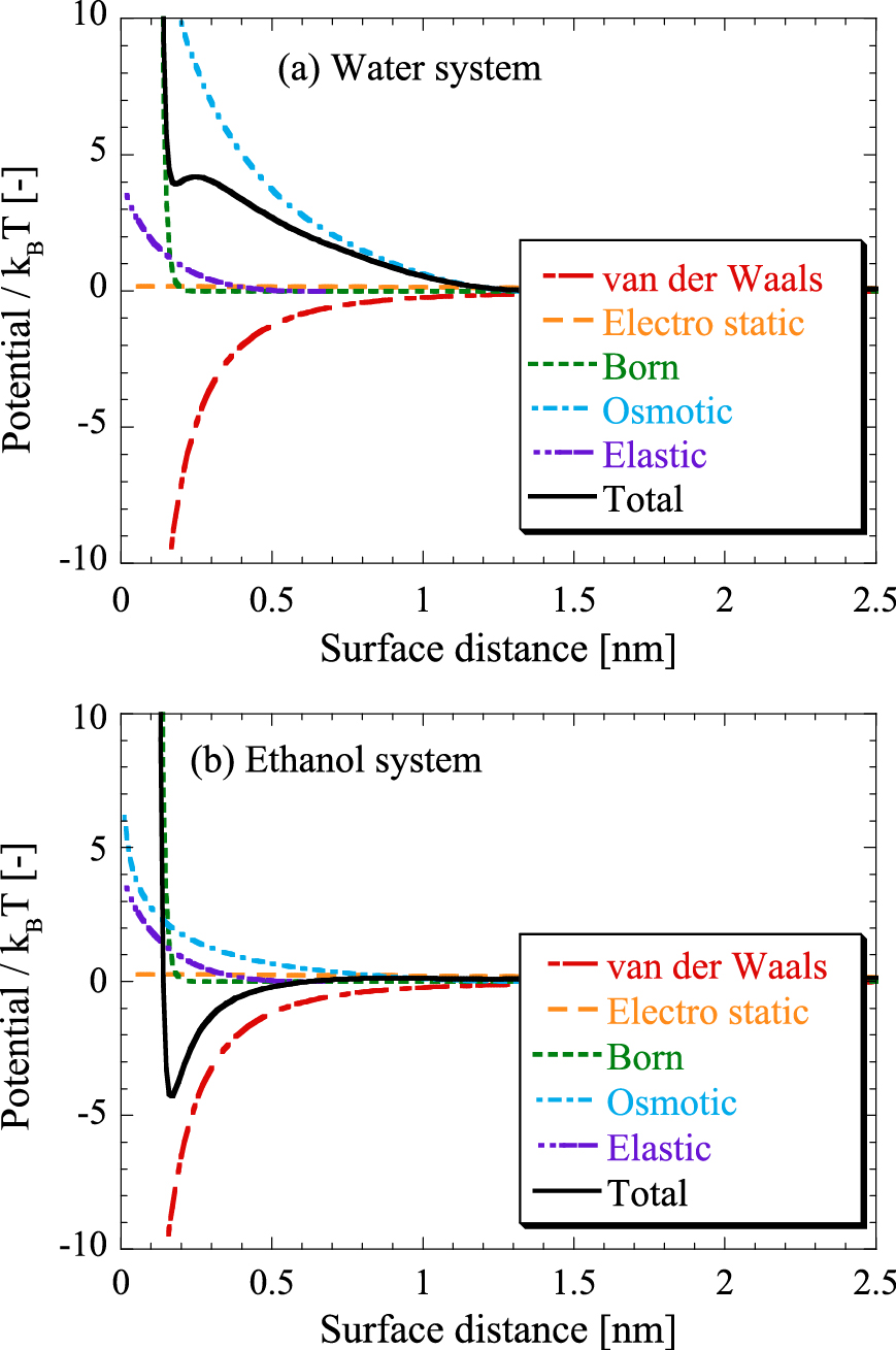
Table 1
Parameter values used for the calculation of particle interaction between two spherical 1-thioglycerol-capped ZnS NPs in water or ethanol systems.
| Parameter |
Water system |
Ethanol system |
| Hamaker constant [J] |
1.65 × 10⁻¹⁹ |
1.53 × 10⁻¹⁹ |
| Refractive index of solvent |
1.33 |
1.36 |
| Relative dielectric constant of solvent |
78.3 |
24.6 |
| Surface potential of NPs [mV] |
−16 |
+35 |
| Debye-Hückel parameter [nm−1] |
1.04 × 10⁻³ |
5.52 × 10⁻⁵ |
| Solvent molar volume [m3/mol] |
1.81 × 10⁻⁵ |
5.86 × 10⁻⁵ |
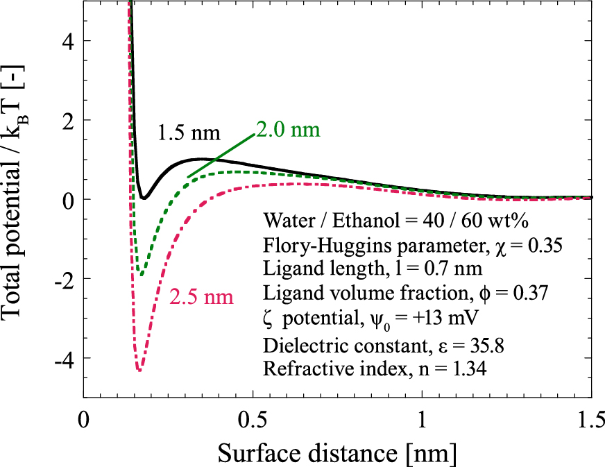
When mixture solvents of water and ethanol were used as the solution with dispersed 1-tioglycerol-capped ZnS NPs, it was experimentally found that a portion of the NPs was precipitated and larger NPs aggregated more than smaller NPs (Komada S. et al., 2012). Fig. 6 shows the calculation results of the size-dependent particle interaction potentials when the particle diameter of 1.5, 2.0, and 2.5 nm in a mixture solution of 40 wt% water and 60 wt% ethanol. According to the calculation results, the small particles have a larger potential barrier and shallower potential depth than the large particles. This means that small particles are more stable because of the large potential barrier and easy redispersion due to the shallow potential depth. This size dependency agrees with the SSP concept that larger particles first flocculate when adding miscible material to the well dispersed colloidal suspension.
4.2 Gas addition
A mixture of an organic solvent and a compressed gas, where the gas dissolves into the liquid phase at an applied pressure less than the vapor pressure of the gas, is called in a gas-expanded liquid (GXL) (Saunders S.R. and Roberts C.B., 2012). GXLs have highly tunable physico-chemical properties between those of the liquid organic solvent and those of the gas based on temperature and gas pressure. The use of GXLs provides several processes such as the synthesis or thin film preparation of NPs. SSP of NPs is one application of GXLs.
Table 2 summarizes the reports of SSP of NPs using CO2 gas as a miscible material. Although most reports concerned novel metals, it is clear that this method has several advantages, i.e., easy control of the mixture properties by adjusting gas pressure and easy gas recycling by depressurization.
Table 2
Reports of SSP using CO
2 gas as the miscible material
| NPs |
Ligand |
Solvent |
Reference |
| Ag, Au |
DDT |
chloroform |
(Shah P.S. et al., 2002) |
| Ag |
DDT |
hexane |
(Mcleod M.C. et al., 2005) |
| Au |
DDT |
hexane |
(Bhosale P.S. and Stretz H.A., 2008) |
| Ag |
DDT |
hexane |
(Von White G. and Kitchens C.L., 2010) |
| Au |
DDT, HT |
hexane–acetone Mixture |
(Saunders S.R. and Roberts C.B., 2011) |
| Au |
DDT |
hexane |
(Vengsarkar P.S. and Roberts C.B., 2013) |
| Au |
OA SA |
DMSO |
(Duggan J.N. and Roberts C.B., 2014) |
| CdSe/ZnS |
TOPO |
hexane |
(Anand M. et al., 2007) |
DDT: dodecanethiol, HT: hexanethiol, OA: oleic acid, SA: steric acid, TOPO: trioctyl phosphine oxide, DMSO: dimethyl sulfoxide
Semiconductor and Si NPs were successfully fractionated by SSP where a miscible (poor) solvent was added to a (good) solvent dispersed NPs well. Table 3 listed some reports using SSP with two-solvents system. In case of semiconductor NPs, there are two categories from the point of a good solvent; aqueous (water) and nonaqueous solvent (alcohol, toluene, chloroform). Whatever water or nonaqueous solvent was used as a good solvent, alcohol was usually chosen as a poor solvent. Murray et al. (Murray C.B. et al., 1993) demonstrated size separation of CdE (E = S, Se, or Te) NPs capped with TOPO using SSP with 1-butanol as a good solvent. Vossmeyer et al. (Vossmeyer T. et al., 1994) reported that narrower-sized samples of CdSe NPs capped with 1-thioglycerol were obtained by SSP using water as a good solvent. Mastronardi et al. (Mastronardi M.L. et al., 2012) classified Si NPs by size, and reported that the PL quantum yield of the NPs decreased with decreasing size.
Table 3
Report of SSP using poor solvent
| NPs |
Ligand |
good solvent |
poor solvent |
Reference |
| CdE E = S, Se, Te |
TOPO |
1-butanol |
methanol |
(Murray C.B. et al., 1993) |
| CdSe, CdTe, InP |
TOP, TOPO |
toluene, n-hexane, chloroform |
methanol |
(Talapin D.V. et al., 2002) |
| InAs:Mn |
TOP |
chloroform |
ethanol |
(Stowell C.A. et al., 2003) |
| GaSe |
1-HAD |
methanol |
octane |
(Chikan V. and Kelley D.F., 2002) |
| CdS |
1-TG |
water |
ethanol, acetone, 2-propanol |
(Vossmeyer T. et al., 1994) |
| ZnS |
cysteine |
water |
ethanol |
(Bae W. and Mehra R.K., 1998) |
| CdTe |
1-TG, TGA, 2-ME |
water |
2-propanol |
(Gaponik N. et al., 2002) |
| ZnSexTe1−x |
TGA |
water |
2-propanol |
(Li C. et al., 2008) |
| ZnS:Mn |
1-TG |
water |
2-propanol |
(Komada S. et al., 2012, Segets D. et al., 2013) |
| Si |
octadecene |
chloroform |
methanol |
(Li X. et al., 2004) |
| Si |
1-octene |
toluene |
methanol |
(Liu S.M. et al., 2006) |
| Si |
allylbenzene |
toluene |
methanol |
(Mastronardi M.L. et al., 2012) |
TOPO: trioctylphosphine oxide, TOP: trioctylphosphine, 1-HDA: 1-hexadecylamine, 1-TG: 1-thioglycerol, TGA: thioglycolic acid, 2-ME: 2-mercaptoethanol
Segets et al. (Segets D. et al., 2013) evaluated the particle size distributions of 1-tioglycerol-capped ZnS NPs before and after SSP and quantitatively discussed the classification efficiencies of SSP, such as cut size, separation efficiency, and sharpness of classification from the powder technology field.
4.4 Salt addition
Zhao et al. (Zhao W. et al., 2010) performed separations of oligonucleotide-capped Au NPs mixture of different sizes by salt-induced aggregation. The larger sized NPs aggregated at lower salt concentration, while the smaller NPs were in supernatant due to the combination of van der Waals attraction and electrostatic repulsion by negatively charged oligonucleotides. They demonstrated the separation performances of 10/20 nm mixture at 0.3 M NaCl with 10 mM sodium phosphate buffer (SPB) solution and of 20/40 nm mixture at 0.1 M NaCl with 10 mM SPB solution.
Wang et al. (Wang C.L. et al., 2010) reported the SSP of CdTe NPs stabilized 3-mercaptopropionic acid or thioglycolic acid in an aqueous solution by adding MgCl2 solution. They compared this with SSP by adding 2-propanol as a poor solvent. They concluded that SSP added salt was simpler and more rapid than SSP added poor solvent because the condensation and heating processes were difficult for the latter SSP operation. Moreover, the cost efficiency of SSP with an added salt was higher, making it possible for use on a large production scale.
;%0A%09%09%09newWindow.document.open();%0A%09%09%09newWindow.document.write('<img src=%22./Graphics/32_2015023_7.jpg%22>');%0A%09%09%09newWindow.document.close();%0A%09%09)