Abstract
Although the deflector wheel classifier is the dominant separation device in the industrial separation of fine-grained particle fractions, the classifying mechanisms at high particle loadings are still not described and understood sufficiently. The existing models for the calculation of the separation efficiency, which are mostly based on a single particle’s fate, fail to capture the behavior at high particle loading where particle-particle and particle-wall collisions are encountered. To overcome this knowledge gap, a high-speed camera was used to analyze the particle movement in the separation process of a deflector wheel classifier representing real physical conditions. It is shown that particle-particle and particle-wall collisions must be included in a consistent theoretical model to represent the effective particle behavior in the separation process. In addition, the influence of process parameters such as revolution rate and mass loading on the separation efficiency of a deflector wheel classifier at high loadings is presented here.
1. Introduction
Air classification is an important step in the production of many industrial powders. According to Rumpf (Rumpf H. and Raasch J., 1962; Rumpf H. and Leschonski K., 1967; Rumpf H. et al., 1974), the basic task of this process is to classify a mixture of particles of different sizes into a fine and a coarse particle fraction. Since product characteristics and quality are closely related to the particle size, products with a narrow particle size distribution are desired, e.g. for color pigments and abrasive powders (Leschonski K., 1988, 1996). In contrast to classifiers with unrestricted flow such as the spiral air classifier with a free vortex, the deflector wheel classifier produces a forced vortex due to the rotating paddles; this has been stated as being less dependent on the mass loading (Leschonski K., 1988, 1996; Rumpf H. and Raasch J., 1962; Rumpf H. and Leschonski K., 1967; Rumpf H. et al., 1974).
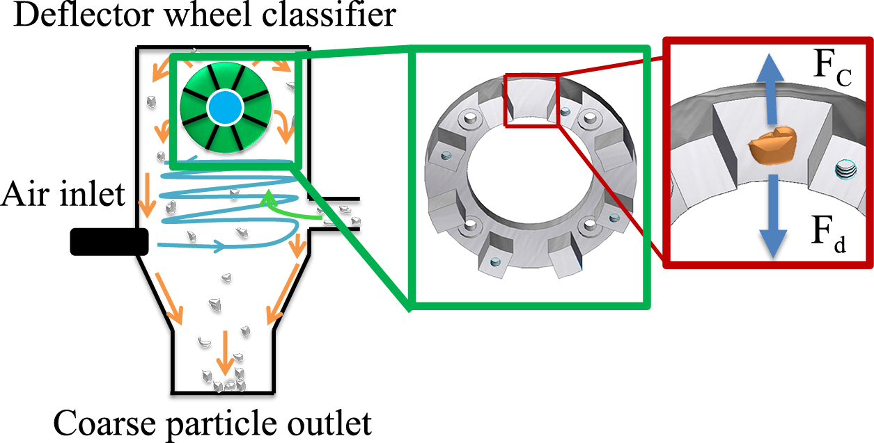
The underlying conception is that the particles experience a centrifugal force in the rotational flow field which is counteracted by the drag of the air flowing inwards between the paddles (cf. Fig. 1) (Rumpf H. and Raasch J., 1962). Coarse particles are deflected on the outer edge of the deflector wheel, while fine particles follow the air flow through the deflector wheel and are separated later from the air flow by an aero-cyclone (Leschonski K., 1988, 1996; Rumpf H. and Raasch J., 1962; Rumpf H. and Leschonski K., 1967; Rumpf H. et al., 1974).
In the last century, Rumpf (Rumpf H. and Raasch J., 1962; Rumpf H. and Leschonski K., 1967; Rumpf H. et al., 1974), Molerus (Molerus O., 1967; Molerus O. and Hoffmann H., 1969), Sender, Schubert (Schubert H., 1968) and Husemann (Husemann K., 1998) developed separation models which describe the particle behavior and the separation efficiency of a deflector wheel classifier only on the basis of geometrical and equilibrium considerations. These models, which consider the behavior of a single particle under the influence of the centrifugal force and drag, are applicable for calculation of the cut point using several empirical coefficients, which can only be obtained from experiments. However, they suffer from several drawbacks. First, the dependency of the empirical parameters on the operating conditions cannot be attributed to a physically sound picture of the separation process. Second, the particle-paddle and particle-particle collisions which become significant at higher loadings are not taken into account. To overcome this knowledge gap Galk (Galk J., 1995) and Füchsel (Füchsel S., 2012) examined the influence of the particle loading on the separation characteristics of a deflector wheel classifier. During these experiments, Galk found a decrease in the ratio of the measured to the theoretical cut point at an increasing mass loading accompanied by a decrease of the separation sharpness. He explained this phenomenon with a retroactive effect of the feed over impulse exchange onto the fluid flow between the separating paddles. According to Galk, this momentum exchange leads to a deceleration of the drag flow near the feed inlet (Galk J., 1995).
Bauer (Bauer U., 2002) extended the studies into the submicron particle range and observed that in this regime also, the material mass flow has an influence on the position and slope of the calculated separation curves under otherwise constant experimental conditions. Based on his experimental results, he hypothesized that different sections of the separation efficiency curve are directly related to the geometry of different parts of the classifier (Stender M. et al., 2015). This interesting approach may explain our observations—which will be treated in future work but are out of the scope of the present contribution.
While for quite a while, little attention has been paid to the flow field through the paddles of the deflector wheel, Legenhausen (Legenhausen K., 1991) analyzed the flow behavior between the separation paddles using a Laser Doppler Anemometer (LDA) based on a water model. He found that the flow between two separation paddles detaches forming a flow vortex. Later, Toneva (Toneva P. et al., 2011) determined the gas flow behavior in a deflector wheel classifier using Particle Image Velocimetry (PIV) and Computational Fluid Dynamic (CFD) simulations. In agreement with Legenhausen they found a detachment of the gas flow from the paddles accompanied by a gas vortex between the separation paddles. Further, Toneva demonstrated that the vortex formation leads to a constriction of the particle flow and an increase in the inward radial gas velocity. Although they neglected the influence of particle-particle collisions on the separation behavior, their numerical calculations indicated that the particles frequently collide with the separation paddles where coarse particles leave the separation zone faster than fine particles. The calculations of Tenova have also shown that the coarse particles rebound in both inside and outside direction, which leads to a deterioration of the separation sharpness. Deduced from the calculated trajectories, a large proportion of the particle stream is not transported into the inside of the separation wheel. On the contrary, their calculations have shown that a particle accumulation in the flow stream near the outside edge of the separation wheel is possible. According to Toneva, this accumulation will lead to a deterioration of the separation sharpness due to long residence times and particle-particle interactions (Spötter C. et al., 2015; Stender M. et al., 2015; Toneva P. et al., 2011).
In order to transfer the simulation results of Toneva et al. to studies at high loadings, Stender et al. (Stender M. et al., 2015) reconstructed a deflector wheel classifier type Hosokawa Alpine ATP 50. By replacing the two-sided mounting of the wheel axis by a one-sided high-speed ball bearing, they achieved direct optical access to the front side of the separator wheel. With this optical access and using a high-speed camera, initial studies of the gas flow and particle movement in a real separation process of a deflector wheel classifier were carried out. During their experiments, Stender et al. found that at a revolution rate of the deflector wheel of 6000 rpm, a vortex forms near the leading separation paddles. This vortex moves into a separation area between the two separation paddles at an increasing revolution rate and finally reaches the area near the pursuing paddle at a revolution rate of 15,000 rpm. With increasing revolution rate, the vortex increasingly constricts the particle flow stream. Through this study, Stender et al. were able to confirm the model from Legenhausen for the first time under real process conditions. They pointed out that particle-particle and particle-wall collisions affect the separation process (Spötter C. et al., 2015; Stender M. et al., 2015).
To incorporate the real behavior of the gas flow and the particle motion during the separation process into the existing models, it is necessary to extend the considerations of Legenhausen and Toneva et al. to higher particle concentrations. Based on these studies, a better interpretation of feedback effects at higher material loadings and of the particle interactions under real process conditions may be achieved.
While performing separation studies on fly ash, Eswaraiah and Narayanan (Eswarajah C. and Narayanan S.S., 2005) also noticed that the separation process at high loadings is not sufficiently understood to enable development of reliable physically sound models. For this reason, this work aims at the presentation of systematic studies of the separation characteristics of a deflector wheel classifier by varying the revolution rate between 3000 and 15,000 rpm and the material loadings between 1 to 5 %, which may form the basis for an improved model taking into account particle-particle and particle-wall collisions.
2. Theoretical basics
2.1 The operation principle of a deflector wheel classifier
In 1939, Rumpf (Rumpf H. and Raasch J., 1962) described for the first time the extension of a spiral air classifier with a forced eddy sink flow, which is today known as a deflector wheel classifier (cf. Fig. 1). In this type of centrifugal counterflow air classifier, the flow field is formed by superposition of a sink flow and a vorticity flow induced by rotating paddles. The paddles are usually made out of thin plates, which are arranged vertically or obliquely to the separation wheel tangent (Rumpf H. and Raasch J.; 1962, Rumpf H. and Leschonski K., 1967; Rumpf H. et al., 1974).
The feed and the classifying air may be added separately or at the same time into the classifying zone of the deflector wheel classifier. The particles are then carried by the air flow towards the deflector wheel where the separation takes place. In the traditional approach, the particle movement between the paddles is determined by the opposing centrifugal force outwards and drag force inwards. For coarse particles, the centrifugal forces FC dominate the drag forces so that the particles are rejected by the rotating wheel. For smaller particles, the centrifugal forces become less important compared to the drag forces Fd, and the particles are carried inwards where they are sucked into the fine particle outlet. In the following section, a simple model will be outlined which takes into account particle properties such as size and density and operation parameters such as air flow rate, material loading, revolution speed and wheel geometry
2.2 Classic model for cut point
For the following model, spherical particles with a given density are considered which neither interact nor influence each other, i.e. single particles in a uniform flow field, which is not affected by any walls. The flow field consists of a tangential velocity vϕ (circumferential direction) and a radial velocity vr (inward direction). It is assumed that the particles initially have the same tangential uϕ and radial velocity components ur as the classifying air (uϕ = vϕ & ur = vr).
Due to the rotational movement, the particles experience the outwardly directed centrifugal force FC
|
F
C
=
ρ
P
·
V
P
·
(
u
ϕ
2
/
r
) | (1) |
where r is the distance to the rotation axis and uϕ is the particle tangential velocity which is assumed to be equal to vϕ (Bauer U., 2002; Legenhausen K., 1991; Spötter C. et al., 2015).
The drag force depends on the projection area of the particles, the drag coefficient and the relative velocity
and can be written in the following way (Richardson J. F. and Zaki W.N., 1954; Rumpf H. and Raasch J., 1962):
|
F
d
=
c
w
(
R
e
)
·
A
p
·
(
ρ
Fl
/
2
)
·
∣
v
rel
∣
·
v
rel | (3) |
For a certain particle size xt,th, the radial velocity outwards induced by the superposition of centrifugal force and drag is equal to the radial gas velocity inwards so that particles of this size will describe circular trajectories without being classified to neither the fine nor the coarse fraction (idealized equilibrium). By assuming particle motion in the Stokes range, the cut point can be determined by equation (1) and (3) (Bauer U., 2002; Legenhausen K., 1991; Spötter C. et al., 2015):
|
x
t
,
th
=
18
·
η
·
v
r
0
·
r
0
ρ
p
·
v
ϕ
0
2 | (4) |
where r0 is the radial position where the equilibrium occurs. The calculated cut point xt,th at the radius r0 is inversely proportional to the fluid circumferential velocity vϕ and proportional to the square root of the product vrr0. For a given deflector wheel geometry, a small cut point can only be achieved by a high peripheral speed and low radial velocities of the air flow. However, the separation grain size is distributed due to stochastic processes with identical shares into the fine and coarse material fractions (Bauer U., 2002; Legenhausen K., 1991).
2.3 Determination of separation curve and sharpness from experimental data
The separation efficiency T(x) describes the fraction of a feed material, which is contained in the coarse material fraction after classification.
|
T
(
x
)
=
m
C
m
Feed
·
q
3
,
C
(
x
)
q
3
,
Feed
(
x
)
·
100
% | (5) |
Here, feed and coarse materials were analyzed by laser diffraction in discrete size classes as a histogram or cumulative distribution. From the separation efficiency curve, the cut size is obtained for a separation efficiency of 50 % (T(xt) = 50 %). The corresponding sharpness of cut is defined as (Stieß M., 2009):
|
κ
=
(
x
25
/
x
75
)
·
100
% | (6) |
3. Material and method
3.1 Basic constriction and separation method of a deflector wheel classifier
In order to determine the separation characteristics, the modified deflector wheel classifier type Turboplex ATP 50 from Hosokawa Alpine with an aero cyclone and a bag filter system was used, as illustrated in Fig. 2.

As a feed material, limestone (CaCO3) is introduced into the deflector wheel classifier (2) below the rotor via a feed screw attached to the side of the deflector wheel classifier (1). The cumulative particle size distribution of the feed material has an x10,3 value of 5.86 μm, an x50,3 value of 59.86 μm and an x90,3 of 179,54 μm. From the bottom of the housing, the classifying air is supplied into the deflector wheel classifier tangentially via a classifying air pipe (3) equipped with an air filter. The aspirator produces a constant air flow of 75 m3/h. The classifying wheel of the Turboplex ATP 50 has a wheel diameter of 50 mm and is powered by a horizontally positioned shaft. The peripheral speed of the separating wheel was varied using a frequency converter from 7.86 (3000 rpm) to 39.27 m/s (15000 rpm). The rejected coarse material leaves the separator downwards through the central particle lock system outlet (4). The fine material leaves the classifier wheel together with the classifying air stream via a fixed pipe (Spötter C. et al., 2015; Stender M. et al., 2015).
The fine particle fraction is separated from the classifying air by an aero cyclone (6). The fine particles leave the cyclone through a particle lock system into the fines outlet 1 (7). The very fine particles of the fine fraction leave the aero cyclone via the vortex finder and are finally separated in a bag filter system (5). The bag filters are periodically cleaned with compressed air and the particles are collected in a fines outlet 2 (8). By using the particle lock systems (4) and (7) for the separation of the coarse and fine particle fraction, it was possible to take samples while the separation wheel was still running. Therefore, it is possible to take and analyze samples from the starting point of the separation process and at different intervals until the separation process reaches stationary conditions (Spötter C. et al., 2015; Stender M. et al., 2015).
In the present study, an experimental protocol was used to recover the coarse and fine particle fractions. In different runs, the peripheral speed varied between 7.86 and 39.27 m/s, and the mass loading ranged from 1 to 5 %. The sampling procedure consisted of taking subsequent samples for 5 min each with a total collection time of 60 min using a particle lock system shown in Fig. 2 ((4) and (7)). With this time-resolved system, it was possible to determine the time the deflector wheel classifier needs to reach stationary separation behavior.
3.2 Reconstruction of the deflector wheel classifier to permit optical accessibility
In order to determine the separation characteristics of a deflector wheel classifier, Stender et al. (Stender M., et al., 2015) reconstructed the ATP 50 so that an optical access onto the deflector wheel was achieved. In order to maintain the classification conditions and the flow of the separation air, Stender et al. did not change the geometry of the classifying wheel or the neighboring components. In order to realize this, the motor of the wheel and the outlet pipe of the fine particle fraction had to be moved to the same side of the deflector wheel. The outlet pipe of the fine particles was realized using a hollow shaft supported by two high-speed spindle bearings (A), driven by a flat belt (B) which is sealed with an oil-soaked gasket. The drive of the hollow shaft takes place via a 1:3 gearing which is powered by a frequency-controlled three-phase asynchronous motor (D) (see Fig. 3) (Stender M. et al., 2015).
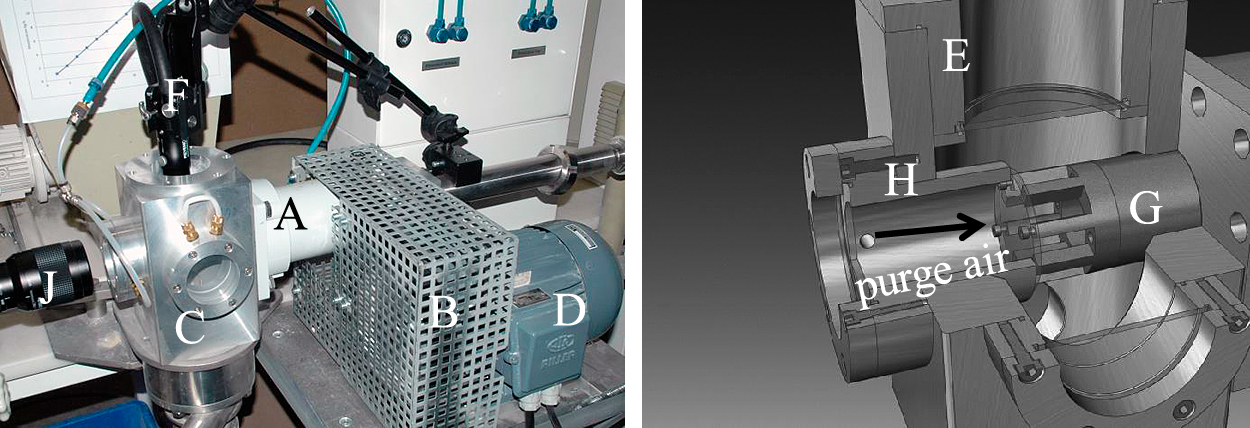
For the optical access to the classifying wheel, specially designed viewing windows were installed on the top (E) and on the side (H). The windows were placed in the side wall and the ceiling of the housing. Special glass discs of the type Mirogard were used for the windows which exhibit anti-reflective properties on both sides thus leading to a high transparency. A high-speed Keyence VW-600M camera was placed in front of the window (cf. Fig. 3 (J)) to visualize the motions of the particles during the separation process. In order to prevent light reflections, the camera was aligned in a 90° angle to the illumination realized with a tripod lamp across the ceiling window (Spötter C. et al., 2015; Stender M. et al., 2015).
3.3 Calculation of the material loading
Besides the circumferential speed, also the mass loading (ML) was varied in this study. According to equation (7), the mass loading was calculated by dividing the feed mass flow rate by the separation air mass flow rate (Stieß M., 2009):
|
M
L
=
f
e
e
d
m
a
s
s
f
l
o
w
[
kg
h
]
s
e
p
a
r
a
t
i
o
n
a
i
r
m
a
s
s
f
l
o
w
[
kg
h
] | (7) |
The aspirator of the deflector wheel classifier provided a constant air flow rate of 75 m3/h, corresponding to an air mass flow rate of 90.13 kg/h. The mass loading was varied between 1 and 5 % (Table 1).
Table 1
Mass loading of the experiments at stationary conditions from 1 to 5 %.
| Mass loading (ML) |
Feed mass flow |
Separation air mass flow |
| [%] |
[kg/h] |
[g/min] |
[kg/h] |
| 1 |
0.903 |
15.05 |
90.31 |
| 2 |
1.806 |
30.10 |
90.31 |
| 3 |
2.709 |
45.15 |
90.31 |
| 4 |
3.612 |
60.20 |
90.31 |
| 5 |
4.515 |
75.25 |
90.31 |
In section 5 of this study, a new model approach for the separation of a deflector wheel classifier will be presented. This model includes as a new parameter the thickness H of the particle layer which is formed by the impacting and rebounding particles close to the pursuing paddle. In order to determine this parameter, a particle cannon (cf. Fig. 4) was constructed which is able to image particles with sizes from 500 to 2000 μm at a velocity up to 80 m/s where the lower particle size is given by the camera resolution which also depends on the particle material. Since the limestone particles exhibited a mediocre contrast, the dependence of H on impact velocity and mass loading was investigated for quartz particles. During each experiment, particles were accelerated by means of an elastic ribbon under tension to different velocities (finger of a rubber glove). The particles leave the metal tube and collide with an impaction plate. While at very low loadings, the coefficient of restitution for single particles can be determined from the initial and rebounding velocity (en = vr/vi), at higher loadings, where significant particle-particle collisions occur, the particle layer thickness H is measured from images of the bulk behavior obtained with the high-speed camera.

Since the boundaries of the particle layer were not sharp but rather diffuse, the thickness was determined from the distribution of the gray scale values evaluated with the software ImageJ. As a criterion for the extension of the layer, the position was recorded where the gray scale value had dropped to 80 % of the maximum value.
4. Experimental results
4.1 Visualization and parametrization of gas and particle flow in the separation zone
The following results present the gas flow and the particle motion in the area between two separation paddles (separation zone). While for the visualization of the gas flow very fine limestone particles were used, the motion of coarser particles was visualized with coarser limestone particles (x50,3 of 59.86 μm). As tracers, fine limestone particles with an x50.3 of 2.15 μm were used which follow the gas flow without lag and without classification. To catch the gas flow behavior, due to some inhomogeneous distribution of the fine particles, the discernible contrast points were tracked on subsequent images. Using the software Motion analyzer VW 9000, the motion of these fine particle accumulations was represented by lines of arrows.
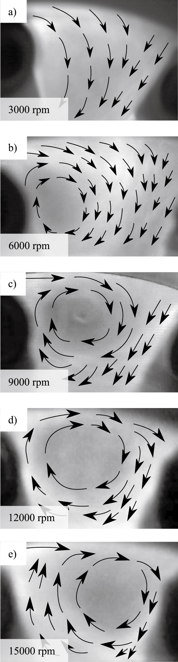
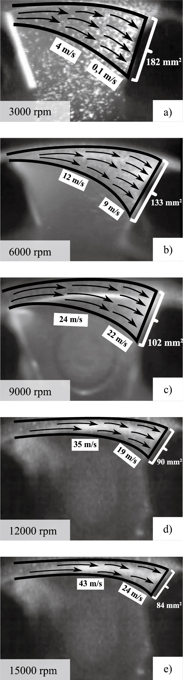
In Fig. 5a), it is shown that at a revolution rate of 3000 rpm, the limestone tracer particles pass the whole separation area in an arc-like flow. The gas flow starts to be deflected slightly in the left/middle section of the classifying zone, while near the pursuing paddle, the gas flows in straight lines. Nevertheless, the gas flow of the very fine limestone particles passes the entire classification area at a revolution rate of 3000 rpm. At the beginning, the coarse limestone particles (Fig. 6a)) follow the gas flow into the separation zone, but later they continue their motion towards the pursuing paddle deviating from the gas flow due to their higher inertia. Only at this low revolution rate is the spatial distribution of the particles relatively homogeneous over the classification area as a consequence of the less deviated incoming particles and deflected larger particles (cf. Fig. 6a)).
From subsequent images, the particle velocity relative to the pursuing paddle was measured using the Motion analyzer VW 9000 software. Interestingly, the particle velocity, initially close to the peripheral speed of the paddle, decreased as the paddle approached. This deceleration effect could be caused either by bouncing particles colliding with the approaching particles or by peripheral air flow created by the paddle motion, or a combination of both. In any case, the deceleration of the approaching particles was observed at all revolution rates, as indicated by the relative velocities given in Fig. 6.
For higher revolution rates, a vortex is formed (cf. Fig. 5b–e) which leads to a constriction of the particle flow, thereby focusing especially the coarse particles to hit the pursuing paddle on a smaller area (Fig. 6b–e) (Stender M. et al., 2015).
At an increased revolution rate of 6000 rpm, the tracer particle flow (Fig. 5b) begins to form a vortex on the left side of the separation area. This vortex leads to a constriction of the particle flow, thereby focusing it onto a smaller area of the impaction paddle (Fig. 6b) (Stender M. et al., 2015).
The vortex begins to move away from the leading separation paddle into the middle of the separation area if the revolution rate is increased further to 9000 rpm (Fig. 5c). With increasing revolution rate (Fig. 5d–e), the vortex moves closer and closer to the pursuing paddle. Fig. 7 illustrates the model of the vortex formation and the particle motion in the separation zone.
Using the parametrization shown in Fig. 7, the flow field between the separation paddles was determined as a function of the revolution rate. The results illustrate the movement of the vortex leading to a constriction of the gas flow which depends on the revolution rate. Regarding the separation process, the constriction of the flow results in an increased inwards radial gas velocity. This should facilitate the entrainment of coarser particles according to the classic model outlined in chapter 2.2. However, this effect was not observed in the separation curves as discussed in chapter 4.3.
While the lateral position of the vortex between the paddles depends on the peripheral speed, the radial position does not change (cf. Fig. 8a). At the same time, the size of the vortex dv increases linearly with peripheral speed up to about 32 m/s, at which point it approaches a constant value given by the geometric constrictions of the paddles (cf. Fig. 8b). In all experiments performed here, the peripheral speed vs of the separating wheel was higher than the circumferential component of the classifying air vϕ (vϕ/vs < 1), leading to a clockwise rotating gas vortex for an anticlockwise rotating wheel in agreement with the results of the LDA measurements on a water model by Legenhausen (Legenhausen K., 1991).
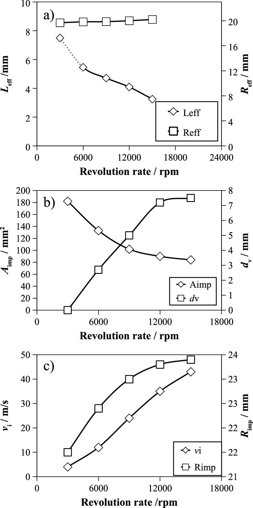
For the classifier geometry used, it was observed that the particles were initially nearly at rest so that the relative velocity was mainly determined by the motion of the paddles as shown in Fig. 8c). As a consequence of the vortex behavior, the incoming particles are increasingly focused onto an impaction area Aimp of the pursuing paddle with increasing peripheral speed (cf. Figs. 6 (b–e) & 8b). The impaction area is reduced in size and moves, on average, to the outer edge with increasing peripheral speed as indicated by the parameter Rimp (cf. Fig. 8c).
After the impaction, the coarse particles are reflected at a reduced speed relative to the pursuing paddle in random directions. However, in an absolute coordinate system, the particles experience much higher velocities after the rebound which is important for the centrifugal force. At low material charge, it is possible that a single particle bounces from the pursuing paddle almost unimpeded to the opposite leading paddle. With an increasing material charge and constriction of the particle flow (cf. Figs. 6 and 8), the rebounding particles collide with subsequent feed particles in a zone near the pursuing paddle. This interaction decelerates the approaching particles as well as the rebounding particles. With an increase in particle concentration, the frequency of particle-particle collisions also increases which reduces the extension of the collision zone as indicated by a particle layer in the vicinity of the pursuing paddle (cf. Fig. 16).
4.2 Transition from instationary to stationary separation behavior
In the following sections, the particle separation behavior will be discussed. Since the separation process between the paddles is very fast (in the ms range), it may be hypothesized that the overall separation process quickly reaches a steady state. However, in the following text it will be shown that, depending on the revolution rate and material loading, it may take several minutes up to over 50 min to reach a stationary separation behavior.
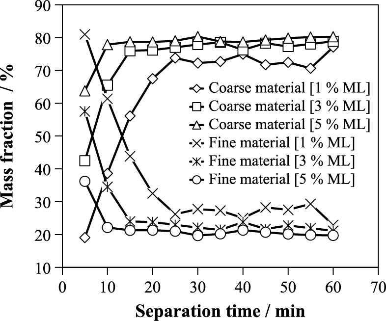
In Fig. 9, the mass fractions of fine and coarse material are shown as a function of the separation time for different mass loadings. For a revolution rate of 9000 rpm, the stationary separation is achieved faster with increasing mass loading and at a higher fraction of coarse material. The same behavior, however, in a mirror symmetrical way, applies for the fine material.
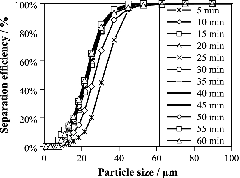
A similar observation was made for the separation curve as shown in Fig. 10. For a revolution rate of 9000 rpm and a mass loading of 3 %, a stationary separation behavior is not achieved before about 25 min.
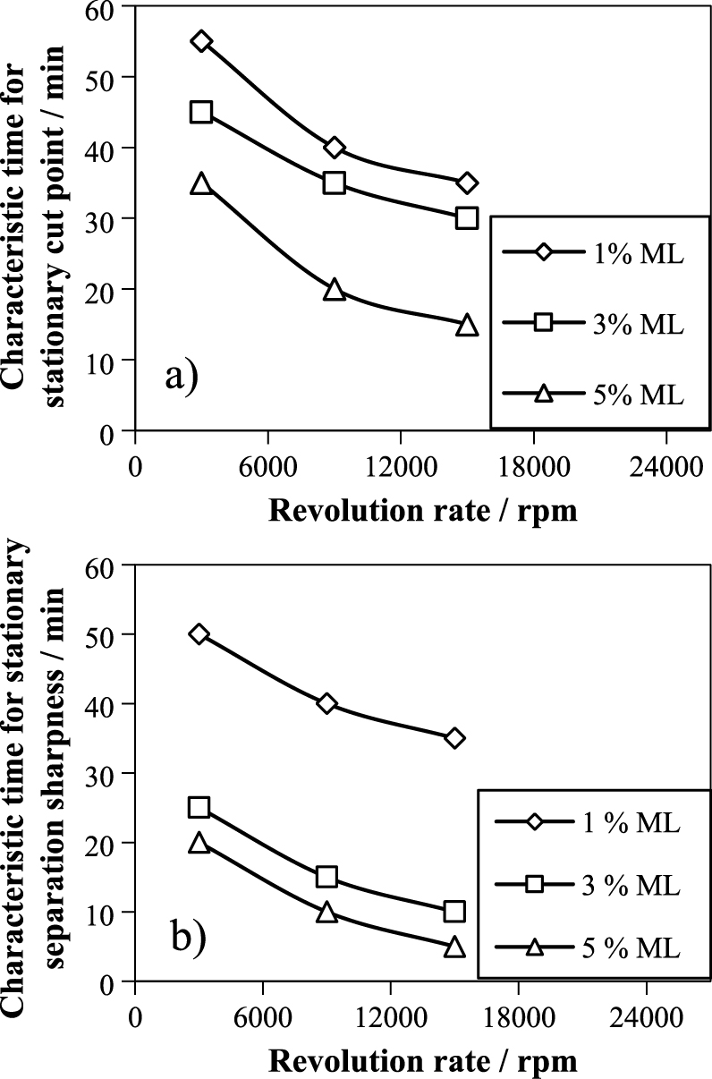
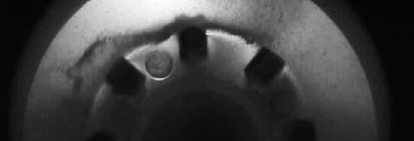
In the following text, the time to reach stationary separation curves which are parametrized by the cut point and the sharpness of cut will be summarized for various revolution rates and mass loadings. As shown in Fig. 11a) and b), the cut point and sharpness reaches steady state faster with an increasing revolution rate and/or increasing mass loading. These results indicate that the particles accumulate in a hold-up ring around the deflector wheel which was in fact seen with the high-speed camera (Fig. 12). This hold-up ring consists of deflected and approaching particles with a concentration which increases significantly near the outer edge of the deflector wheel. When assuming that the capacity of this hold-up ring is constant, the dependence of the characteristic time to reach the steady state on the revolution rate and mass loading becomes obvious. The time to fill the hold-up ring scales inversely with the mass flow rate which in turn is determined by the particle velocity (peripheral speed) and the particle concentration (mass loading).
As shown in the last chapter, the deflector wheel classifier needs a certain time to reach stationary separation behavior, which may take up to 50 min in the worst case (3000 rpm). In the following text, the separation behavior at steady state conditions is outlined.
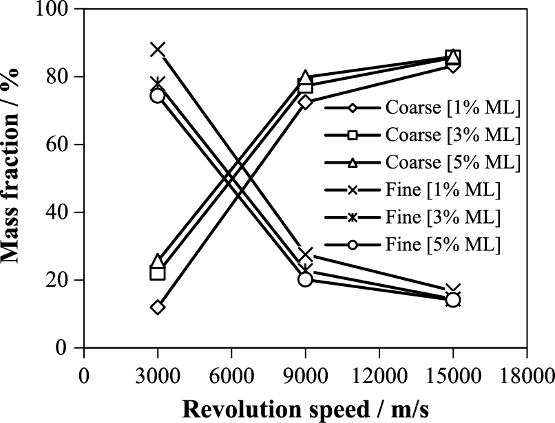
In Fig. 13, the fractions of fine and coarse material are shown as a function of revolution rate and mass loading. With increasing revolution rate and mass loading, the fraction of the coarse material increases where, however, the influence of the revolution rate is dominating the effect of the mass loading. It is clear that the behavior of the fine material fraction is mirror-symmetrical to the coarse material. While the profile of the mass fraction curve remains unchanged, the absolute values of the mass fractions depend on the powder properties such as initial size distribution.
The dominating influence of the revolution rate is also reflected in the separation curves shown in Fig. 14a). While an increase of the revolution rate by a factor of 3 leads to an 83 % decrease of the cut point, an increase of the mass loading of the factor 3 results only in a reduction of 24 % (starting at 1 % and 3000 rpm). The evolution of the cut point for all investigated conditions is shown in Fig. 14b).

In contrast to the cut point, the sharpness of cut is nearly independent of the revolution rate and mass loading. For the limestone particles with a median size of 70 μm, the values varied between 54 and 62 % (cf. Fig. 14c)). This uniformity of the sharpness was deemed to be a consequence of the hold-up ring around the deflector wheel which could act similarly to a pre-filter for the incoming particles. In addition, the particle layer formed at the pursuing paddle may also contribute to a constant sharpness, as further outlined in the discussion. Some experiments with finer limestone particles (median particle size of 40 μm) indicate a similar independence of the sharpness of cut on the revolution rate and mass loading, however, reaching higher average values in the range of 65 %.
5. Discussion
In industrial applications of deflector wheel classifiers, the operation time is usually so long that the time needed to reach the steady state separation may be considered as negligible. However, the reason for this induction time, i.e. the hold-up ring which needs to be filled for stationary operation, can also influence the feed delivery to the classifying wheel with respect to size distribution and initial particle velocity. While the detailed investigation of the characteristics of the hold-up ring is beyond the scope of this contribution, the motion of the particles in the deflector wheel will be treated in the following text. From the high-speed camera images presented in chapter 4.1, it is concluded that the particles are nearly at rest in an absolute coordinate system, i.e. the deflection paddles approach the particles which start to be drawn into the inter-paddle space by the radial gas flow. Therefore, in the approach phase, the particles have no peripheral speed so that they do not experience a centrifugal force. This result may be different for separators where the particles are accelerated to a certain circumferential speed before entering the classification zone. However, the deflector wheel classifier used here is representative for a significant class of separators. In the case of particles initially at rest, the classic model comparing centrifugal force and drag is not applicable and a physical sound cut size cannot be estimated.
In fact, the particles would experience centrifugal forces only after being hit by the paddle. This phase will be discussed in more detail below. During the approach phase, however, the particles are accelerated in radial direction due to the constriction of the free flow area as a consequence of the vortex. Based on the geometric parametrization of the vortex (cf. chapter 4.1), the particle trajectories relative to the paddles were calculated by numerically integrating the equation of motion. To do so, it was assumed that the paddle approaches the particles at the given peripheral speed while the particles are accelerated in radial direction by the radial inwards gas flow. Since the revolution speed of the vortex and the gas flow at the initial zone between the paddles are not known, it was simply assumed that radial particle motion starts at the vortex in the presence of an accelerating radial gas flow. The radial component of the gas flow was approximated by the total gas flow divided by the cross-sectional area A given by:
|
A
(
r
)
=
D
·
L
(
r
)
=
D
·
[
(
R
v
-
L
eff
)
-
(
r
·
(
2
R
v
-
r
)
)
1
2
] | (8) |
where RV is the vortex radius (=dV/2).
The radial particle motion is then determined by:
|
d
u
r
d
t
=
18
·
η
eff
ρ
p
·
x
2
·
(
v
r
(
r
)
-
u
r
(
r
)
) | (9) |
where Stokes’ regime was assumed and the radial gas velocity was calculated by νr (r) =
V
˙
/A(r).
The calculated trajectories obtained from this simple model are shown in Fig. 15 for three revolution speeds (6000, 9000, 15000 rpm), corresponding to peripheral speeds of 15.71, 23.56 and 39.27 m/s, respectively. In Fig. 15, the calculated particle motion is shown in the coordinate system where the origin is fixed on the outermost point of the leading paddle for limestone particles with sizes of 10, 20, 40, 80 and 160 μm.

From Fig. 15 it is obvious that the particle trajectory in the approach phase depends on the particle Stokes’ number (determined by the particle size and density and radial gas flow velocity) and the peripheral speed of the deflector wheel. However, the radial dispersion of the particles depends also on the effective viscosity ηeff, i.e. the drag coefficient encountered by the particle due to friction with the gas and to particle-particle collisions. Beside the gas properties, this effective viscosity is also a function of the peripheral speed and mass loading and can be approximated following the model of Richardson and Zaki (Richardson J. F. and Zaki W.N., 1954). Although the exact value of ηeff is not known for the particle system observed here, the particle trajectories calculated with the pure gas viscosity are in qualitative agreement with the experimental observations (cf. Fig. 6).
In addition to the calculated particle trajectories, the measured cut sizes (43 μm, 27 μm, 15 μm) for the three revolution rates (6000, 9000, 15000 rpm) are also indicated in Fig. 15. The white arrows indicate the locations of these cut sizes on the pursuing paddle in relation to the calculated trajectories. In this simple model for a given operating condition, the white arrow indicates the position where the feed is distributed in equal parts into the fine and coarse fraction. However, this size-dependent partitioning of the feed between the fine and coarse fraction could not be recorded with the high-speed camera used due to the limited size resolution which was further exacerbated by superposition effects at elevated concentrations.
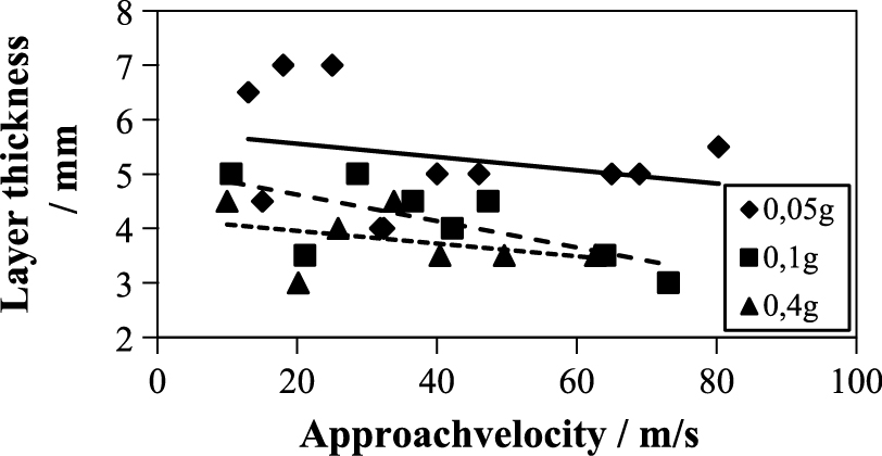
In the rebound phase, the situation near the paddle is much more complicated. The particles bouncing from the paddle collide with the particles just approaching, leading to a very dense particle layer. Due to the limited resolution for the limestone particles, the thickness of this layer could not be determined directly at the paddle from the high-speed camera images. Therefore, off-line experiments with quartz particles which gave a better contrast were performed with the particle cannon (cf. chapter 3.4) to investigate the principal dependencies of the particle layer thickness on the mass loading and approach velocity.
As indicated in Fig. 16, the layer thickness depends more strongly on the mass loading than on the approaching velocity which corresponds to the peripheral speed of the paddle. In this particle layer, the concentration is extremely high so that the particles are prevented from free motion due to frequent particle-particle collisions. Therefore, we hypothesize that depending on the radial position, the different parts of the particle layer experience different centrifugal forces. It is then assumed that at a certain radial position, the centrifugal forces overcome the inwards directed drag on the particle layer. As especially well observed at low peripheral speed, the outer part of the particle layer discharges toward the hold-up ring while the inner part is drawn into the fine fraction. In Fig. 15, the measured cut sizes for the different revolution rates are indicated by white arrows. For each revolution rate, the arrow would indicate the separation of the feed material into a coarser fraction discharged to the outside in the form of streaks and a fine fraction reporting to the inside.
The formation of streaks on the periphery of the deflector wheel was already deduced by Toneva et al. (Toneva P. et al., 2011), who analyzed the gas flow field in a deflector wheel separator. They concluded that particles which are rejected from the pursuing paddle could build particle streaks in the periphery of the deflector wheel, exactly as observed in the high-speed camera images (cf. Fig. 17).
Surprisingly, the occurrence of streaks is periodical with a frequency which depends on peripheral speed and mass loading. So far, however, a detailed analysis of the streak characteristics has not been completed.
Since the detailed investigation of many open issues such as fine particle trajectories and motion, the thickness of the particle layer at the pursuing paddle and the circumferential speed of the vortex is currently restricted by the resolution of the high-speed camera, it is planned for the future to use a microscope objective and a Laser Doppler Anemometer to quantitatively evaluate these phenomena. These measurements, combined with ongoing CFD and DEM calculations, should provide a solid base for the development of a more quantitative separation model.
6. Summary
The performance of a deflector wheel classifier at steady state condition was studied experimentally with a limestone feed material. It was found that the time to reach stationary separation behavior may amount to several tens of minutes depending on mass loading and peripheral speed. In steady state, the separation efficiency curve, separation sharpness and cut point also depend on mass loading and peripheral speed.
The visualization of the separation zone between the paddles of the deflector wheel revealed that the classic separation models do not represent the physics of the separation process adequately. First, the formation and evolution of a vortex forming inside the separation zone as proposed by Legenhausen, Toneva et al. and Stender et al. has to be taken into account. This vortex causes a constriction of the radial fluid flow in the separation zone. Secondly, in an absolute coordinate system, the particles have nearly no peripheral speed in the approach phase towards the pursuing paddle and therefore they do not experience centrifugal forces in this phase. Third, the particles bouncing from the paddle collide with the incoming particles and form a dense layer close to the pursuing paddle. We hypothesize that the particles spread radially in the approach phase while the separation into coarse and fine fraction occurs in the dense layer close to pursuing paddle. In this model, the separation occurs at a special radial position on the pursuing paddle. Combining these considerations with the measured cut points may provide the base for more quantitative separation models taking into account operational and particle parameters.
As confirmed by high-speed camera images, the coarse fraction discharges as streaks to the periphery of the deflector wheel, probably contributing to the hold-up ring which forms around the deflector wheel. This hold-up ring which, to the best of our knowledge, is described here for the first time seems to be responsible for the induction time to reach stationary separation conditions.
Finally, the sharpness of cut was observed to be virtually constant, only marginally influenced by mass loading and peripheral speed. While this fact may facilitate the development of a separation model significantly, i.e. reducing the task to the determination of the cut point, the reason for the constant sharpness of cut is unclear so far. This phenomenon indicates that the interplay between particle approach, layer formation, streaks and hold-up ring is far from being understood and needs much more in-depth investigations.
Acknowledgements
The German research foundation is gratefully acknowledged for their financial support of this work in context of the priority program SPP 1679 (“Dyn. Simulation of cross-linked solid processes”) under the grand sign WE 2331/16-1. In addition, special thanks go to B.Sc. Leonard Hansen for his work on the model approach and the particle cannon.
Abbreviations
CFD
Computational Fluid Dynamics
LDA
Laser Doppler anemometry
PIV
Particle image velocimetry
Greek letters
ρFl
Fluid density
ρP
Particle density
η
Dynamic viscosity
Equation letters
Ap [m
2]
Particle surface
cw(
Re) [−]
Coefficient of resistance
Fc [N]
Centrifugal force
FW [N]
Drag force
g [m/s
2]
Gravity
ɡ
C [−]
Coarse material proportion
k [%]
Separation sharpness
mC [kg]
Coarse material mass
mFeed [kg]
Feed material mass
qFeed [μm
−1]
Particle density distribution of the feed
qC [μm
−1]
Particle density distribution of the coarse particle fraction
Q3 [−]
Particle size distribution
r0 [m]
Separation radius
Re [−]
Particle-Reynolds-number
T(
x) [%]
Separation efficiency
up [m/s]
Particle circumferential velocity
VP [m
3]
Particle volume
vrel [m/s]
Relative velocity
vr0 [m/s]
Radial fluid velocity at the radius r0,
vϕ [m/s] Fluid circumferential velocity at radius r0
x [μm]
Particle size
x25 [μm]
Particle size at 25 % of the separation efficiency curve
x75 [μm]
Particle size at 75 % of the separation efficiency curve
xc [μm]
Median cut point
Author’s short biography
Christian Spötter
Christian Spötter obtained his M.Sc. degree in 2014 from Clausthal University of Technology, Clausthal-Zellerfeld, with the study of environmental process engineering. For his master’s thesis he researched the optimization of an ilmenite froth flotation by using new technologies. He graduated from the Institute of Mineral and Waste Processing, Clausthal University of Technology in 2014 headed by Prof. Dr.-Ing. D. Goldmann. His PhD work focuses on the characterization of the separation behaviour of a deflector wheel classifier by means of visualization of the separation of air and the particle flow.
Kurt Legenhausen

Dr.-Ing. Kurt Legenhausen studied mechanical engineering at Clausthal University of Technology and received his Dipl.-Ing. in 1981. In 1983, he joined the Institute of Particle Technology at Clausthal University of Technology (Head: Prof. Kurt Leschonski). He obtained his PhD in 1991 on the investigation of the flow field in a deflector wheel classifier. Afterwards he was chief engineer at the institute, which has been headed by Prof. Dr. Alfred Weber since 2005. He is managing editor of the Journal of Aerosol Science and assists Prof. Weber at the annual Clausthal course on “Particle Measuring Technologies”.
Alfred P. Weber

Prof. Dr. Alfred Weber studied physics and obtained his PhD in aerosol physics at ETH Zurich in 1993. After a stay in the group of Prof. Sheldon Friedlander at UC Los Angeles (UCLA), he joined the group of Prof. Gerhard Kasper at the Karlsruhe Institute of Technology (KIT) in 1996. He received the Smoluchowski Award in 2001 for his work on aerosol nanoparticles. Since 2005, he is a full professor for Particle Technology at the Clausthal University of Technology. He is the editor-in-chief of the Journal of Aerosol Science. His research focuses on the gas-phase synthesis and applications of nanoparticles.
References
- Bauer U., Zur trennscharfen Feinstsichtung in Fliehkraft-Abweiseradsichtern, Dissertation, TU Clausthal (2002).
- Eswaraiah C. and Narayanan S.S., Studies on a rotating wheel air classifier for size classification of fly ash, Mineral process technology, Trichy India (2005) 465–472.
- Füchsel S., Trockene Desagglomeration von Nanopartike-lflocken in einer Gegenstrahlmühle mit kombinierter Onlineüberwachung, Dissertation, Clausthal (2012).
- Galk J., Feinsttrennung in Abweiseradsichtern, Dissertation, TU Clausthal (1995).
- Husemann K., Modelling of Dry Countercurrent Classification, Aufbereitungs-Technik 39, Freiberg (1998) 279–286.
- Legenhausen K., Untersuchung der Strömungsverhältnisse in einem Abweiseradsichter, Dissertation, TU Clausthal (1991).
- Leschonski K., Windsichter, verfahrenstechnische Maschinen zur Herstellung definierter pulverförmiger Produkte, Jahrbuch 1988 der Braunschweigischen Wissenschaftlichen Gesellschaft, Braunschweig (1988).
- Leschonski K., Classification of particles in the submicron range in an impeller wheel air classifier, KONA Powder and Particle Journal, 14 (1996) 52–60.
- Molerus O., Stochastisches modell der gleichgewichtssichtung, Chemie Ingenieur Technik, 39 (1967) 792–796.
- Molerus O., Hoffmann H., Darstellung von windsichtertrennkurven durch ein stochastisches modell, Chemie Ingenieur Technik, 41 (1969) 340–344.
- Richardson J.F., Zaki W.N., The sedimentation of a suspension of uniform spheres under conditions of viscous flow, Chemical Engineering Science, 3 (1954) 65–73.
- Rumpf H. and Raasch J., Desagglomeration in Strömungen, Karlsruhe (1962).
- Rumpf H., Leschonski K., Prinzipien und neuere Verfahren der Windsichtung, Chemie Ingenieur Technik, 39 (1967) 1231–1241.
- Rumpf H., Sommer K. and Stieß M., Berechnung von Trennkurven für Gleichgewichtsichter, Verfahrenstechnik (8), Karlsruhe (1974).
- Schubert H., Aufbereitung fester mineralscher Rohstoffe—Band 1, Leipzig (1968).
- Stender M., Legenhausen K. und Weber A.P., Visualisierung der Partikelbewegung in einem Abweiseradsichter, Chemie Ingenieur Technik, 87 (2015) 1392–1401..
- Stieß M., Mechanische Vefahrenstechnik—Partikeltech-nologie 1, Springerverlag Konstanz (2009).
- Spötter C., Stender M., Legenhausen K. und Weber A.P., Dynamische Trenncharakteristik von Abweiseradsichtern, Produktgestaltung in der Partikeltechnologie Band 7, Faunhofer Verlag (2015).
- Toneva P., Epple P., Breuer M., Peukert W., Wirth K.-E., Grinding in an air classifier mill Part I: Characterisation of the one-phase flow, Powder Technology, 211 (2011) 19–27.
- Toneva P., Wirth K.-E., Peukert W., Grinding in an air classifier mill—Part II: Characterisation of the two-phase flow, Powder Technology, 211 (2011) 28–37.


;%0A%09%09%09newWindow.document.open();%0A%09%09%09newWindow.document.write('<img src=%22./Graphics/35_2018003_20.jpg%22>');%0A%09%09%09newWindow.document.close();%0A%09%09)
;%0A%09%09%09newWindow.document.open();%0A%09%09%09newWindow.document.write('<img src=%22./Graphics/35_2018003_19.jpg%22>');%0A%09%09%09newWindow.document.close();%0A%09%09)
;%0A%09%09%09newWindow.document.open();%0A%09%09%09newWindow.document.write('<img src=%22./Graphics/35_2018003_18.jpg%22>');%0A%09%09%09newWindow.document.close();%0A%09%09)