
- Issue 16 Pages 2157-
- Issue 15 Pages 1805-
- Issue 14 Pages 1613-
- Issue 13 Pages S1141-
- Issue 12 Pages S1037-
- Issue 11 Pages 1443-
- Issue 10 Pages 1273-
- Issue 9 Pages 1077-
- Issue 8 Pages 917-
- Issue 7 Pages 751-
- Issue 6 Pages 585-
- Issue 5 Pages S389-
- Issue 4 Pages S1-
- Issue 3 Pages 403-
- Issue 2 Pages 233-
- Issue 1 Pages 19-
- Issue 16 Pages 2153-
- Issue 15 Pages 1977-
- Issue 14 Pages 1813-
- Issue 13 Pages S1285-
- Issue 12 Pages S1043-
- Issue 11 Pages 1667-
- Issue 10 Pages 1481-
- Issue 9 Pages 1231-
- Issue 8 Pages 891-
- Issue 7 Pages 711-
- Issue 6 Pages 538-
- Issue 5 Pages S407-
- Issue 4 Pages S1-
- Issue 3 Pages 347-
- Issue 2 Pages 173-
- Issue 1 Pages 14-
- Issue 16 Pages 1837-
- Issue 15 Pages 1711-
- Issue 14 Pages 1569-
- Issue 13 Pages S1205-
- Issue 12 Pages S1034-
- Issue 11 Pages 1423-
- Issue 10 Pages 1269-
- Issue 9 Pages 1059-
- Issue 8 Pages 925-
- Issue 7 Pages 775-
- Issue 6 Pages 627-
- Issue 5 Pages S287-
- Issue 4 Pages S1-
- Issue 3 Pages 301-
- Issue 2 Pages 147-
- Issue 1 Pages 12-
- Issue 16 Pages 2179-
- Issue 15 Pages 1795-
- Issue 14 Pages 1631-
- Issue 13 Pages S1053-
- Issue 12 Pages S1023-
- Issue 11 Pages 1501-
- Issue 10 Pages 1315-
- Issue 9 Pages 987-
- Issue 8 Pages 767-
- Issue 7 Pages 621-
- Issue 6 Pages 473-
- Issue 5 Pages S305-
- Issue 4 Pages S1-
- Issue 3 Pages 299-
- Issue 2 Pages 151-
- Issue 1 Pages 16-
- Issue 16 Pages 1945-
- Issue 15 Pages 1699-
- Issue 14 Pages 1531-
- Issue 13 Pages S1055-
- Issue 12 Pages S1013-
- Issue 11 Pages 1367-
- Issue 10 Pages 1215-
- Issue 9 Pages 1087-
- Issue 8 Pages 887-
- Issue 7 Pages 721-
- Issue 6 Pages 507-
- Issue 5 Pages S317-
- Issue 4 Pages S1-
- Issue 3 Pages 343-
- Issue 2 Pages 187-
- Issue 1 Pages 17-
- Issue 16 Pages 2405-
- Issue 15 Pages 2067-
- Issue 14 Pages 1865-
- Issue 13 Pages 1675-
- Issue 12 Pages S1055-
- Issue 11 Pages S1015-
- Issue 10 Pages 1479-
- Issue 9 Pages 1129-
- Issue 8 Pages 895-
- Issue 7 Pages 711-
- Issue 6 Pages 545-
- Issue 5 Pages S325-
- Issue 4 Pages S1-
- Issue 3 Pages 369-
- Issue 2 Pages 193-
- Issue 1 Pages 16-
- Issue 16 Pages 2573-
- Issue 15 Pages 2261-
- Issue 14 Pages 2073-
- Issue 13 Pages S1111-
- Issue 12 Pages S1001-
- Issue 11 Pages 1867-
- Issue 10 Pages 1657-
- Issue 9 Pages 1409-
- Issue 8 Pages 1043-
- Issue 7 Pages 841-
- Issue 6 Pages 649-
- Issue 5 Pages S415-
- Issue 4 Pages S1-
- Issue 3 Pages 431-
- Issue 2 Pages 225-
- Issue 1 Pages 3-
- |<
- <
- 1
- >
- >|
-
Kohei Ishida, Takuo Nakade, Tsutomu Morikawa, Masao Miyake, Tetsuji Hi ...2017 Volume 103 Issue 5 Pages 209-214
Published: 2017
Released on J-STAGE: April 30, 2017
Advance online publication: February 10, 2017JOURNAL OPEN ACCESS FULL-TEXT HTMLWe have investigated the heat resistance properties of Fe-W alloy films electroplated using an ion exchange membranes - multiple anodes systems. The room temperature hardness of Fe-W alloy film increased with increasing heat treatment temperature and reached HV1200 after the heat treatment at 700°C. While the film was amorphous in the as-plated state, it was partially crystallized by heat treatment at over 600°C, indicating that the increase in the hardness was caused by mechanism of precipitation hardening. The high hardness of the Fe-W film was maintained even when the hardness was measured at high temperatures. Wear resistance of Fe-W alloy film was lower than those of electroplated Ni-W alloy and Cr films in the as-plated states. However, the wear resistance of Fe-W alloy increased and surpassed the values of the Ni-W alloy and Cr films after heat treatment. Fe-W alloy film with a higher W content showed higher resistance to the erosion by molten zinc. No erosion by molten zinc was observed for the Fe-W alloy films containing W more than 35 wt%. The Fe-W alloy film was found to form layered oxide phases on its surface. The oxide layer formed on the surfaces of the Fe-W film, including the inner surface of the cracks in the film, seemed to work effectively as a barrier to the molten zinc erosion.
View full abstractDownload PDF (1404K) Full view HTML -
Takashi Futaba, Akinobu Kobayashi, Yasuto Goto2017 Volume 103 Issue 5 Pages 215-220
Published: 2017
Released on J-STAGE: April 30, 2017
JOURNAL OPEN ACCESS FULL-TEXT HTMLThe effect of substrate crystal orientation on the initial distribution of electrodeposit in Zn and Ni plating with a deposit of 10 mg/m2 or less was investigated by using chemically polished polycrystalline low carbon Al-killed steel sheets. Both Zn and Ni distributed according to the substrate crystalline grain size were identified. However, the trend of the initial distribution was different between Zn and Ni. Zinc mainly deposited on crystal grains that indicated the orientation of α-Fe(110), α-Fe(111) and α-Fe(112). In addition, the deposited Zn had the orientation of Zn (002) in respect of the substrate crystal orientation. These orientations of α-Fe were consistent with those of Zn(002), better than any other orientations. This indicates that the distribution of Zn deposits was affected by the consistency between the Zn(002) and α-Fe orientation. On the other hand, Nickel mainly deposited on crystal grains that indicated the orientation of α-Fe(111), α-Fe(112) and α-Fe(221). The face density of these α-Fe orientations was lower than that of any of the others. Therefore, the Ni deposits had a distribution depending on the face density of α-Fe. This trend is the same as that in displaced Ni plating.
View full abstractDownload PDF (4445K) Full view HTML
-
Jun Haga, Hideaki Sawada, Kohsaku Ushioda2017 Volume 103 Issue 5 Pages 221-229
Published: 2017
Released on J-STAGE: April 30, 2017
Advance online publication: February 08, 2017JOURNAL OPEN ACCESS FULL-TEXT HTMLThe effect of boron (B) on the recrystallization behavior, in particular the growth of the recrystallized grain into unrecrystallized grain, of titanium (Ti) added interstitial atom free (IF) steel sheets was studied from the viewpoint of the solute drag effect considering the interaction between B and Ti atoms. The growth rate of the recrystallized grain at 5% fraction recrystallized decreased with increasing B content. Furthermore, the decrease became more pronounced in the B added steels with the higher Ti content. The interaction energy between B and Ti atoms at the grain boundary was evaluated by the first-principles calculation in the bcc-Fe(111)Σ3[110] symmetrical tilt grain boundary. Attractive interaction between B and Ti atoms was obtained in most of the grain boundary atom sites examined. B segregation at the interface between recrystallized and unrecrystallized grains was concluded to induce Ti segregation through the attractive interaction between B and Ti atoms during interface migration. The mechanism for the suppression in the growth of the recrystallized grains was proposed to be caused by the decrease in the interface mobility caused by the enhanced Ti segregation.
View full abstractDownload PDF (2057K) Full view HTML
-
Daichi Akama, Toshihiro Tsuchiyama, Setsuo Takaki2017 Volume 103 Issue 5 Pages 230-235
Published: 2017
Released on J-STAGE: April 30, 2017
 JOURNAL OPEN ACCESS FULL-TEXT HTML
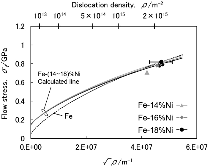
The dislocation strengthening was estimated by applying the dislocation theory for a Fe-18%Ni alloy which has a lath martensitic structure. The yield stress of highly dislocated metals is dependent on both the friction stress and the dislocation strengthening. Regarding the coefficient of dislocation strengthening, it is governed by the shear modulus of metals. Ni addition plays a role in increasing the friction stress but decreases the shear modulus. This means that the coefficient of dislocation strengthening is smaller in the Fe-18%Ni alloy than pure iron. It was confirmed that the yield stress, which was experimentally obtained in Fe-18%Ni alloy, is reasonably explained by the mechanism of dislocation strengthening, taking the effects of Ni into consideration. On the other hand, in the case of lath martensite with a dislocation density of 2×10¹⁵ /m2, it was also found that the effect of Ni addition does not appear on the yield stress because the increment of solid solution strengthening is cancelled out by the decrement of dislocation strengthening.
Relation between dislocation density and the flow stress which was calculated for Fe-(14~18)%Ni and Fe putting the radius of dislocation core (r0) as 3 atomic size (b). Fullsize ImageView full abstractDownload PDF (1052K) Full view HTML
- |<
- <
- 1
- >
- >|