- Issue 16 Pages 995-
- Issue 15 Pages 907-
- Issue 14 Pages 879-
- Issue 13 Pages 803-
- Issue 12 Pages 647-
- Issue 11 Pages 593-
- Issue 10 Pages 551-
- Issue 9 Pages 425-
- Issue 8 Pages 379-
- Issue 7 Pages 355-
- Issue 6 Pages 273-
- Issue 5 Pages 231-
- Issue 4 Pages 187-
- Issue 3 Pages 63-
- Issue 2 Pages 21-
- Issue 1 Pages 1-
- Issue 16 Pages 1251-
- Issue 15 Pages 1165-
- Issue 14 Pages 1033-
- Issue 13 Pages 989-
- Issue 12 Pages 899-
- Issue 11 Pages 795-
- Issue 10 Pages 721-
- Issue 9 Pages 653-
- Issue 8 Pages 569-
- Issue 7 Pages 513-
- Issue 6 Pages 427-
- Issue 5 Pages 395-
- Issue 4 Pages 343-
- Issue 3 Pages 89-
- Issue 2 Pages 35-
- Issue 1 Pages 1-
- Issue 16 Pages 2157-
- Issue 15 Pages 1805-
- Issue 14 Pages 1613-
- Issue 13 Pages S1141-
- Issue 12 Pages S1037-
- Issue 11 Pages 1443-
- Issue 10 Pages 1273-
- Issue 9 Pages 1077-
- Issue 8 Pages 917-
- Issue 7 Pages 751-
- Issue 6 Pages 585-
- Issue 5 Pages S389-
- Issue 4 Pages S1-
- Issue 3 Pages 403-
- Issue 2 Pages 233-
- Issue 1 Pages 19-
- Issue 16 Pages 2153-
- Issue 15 Pages 1977-
- Issue 14 Pages 1813-
- Issue 13 Pages S1285-
- Issue 12 Pages S1043-
- Issue 11 Pages 1667-
- Issue 10 Pages 1481-
- Issue 9 Pages 1231-
- Issue 8 Pages 891-
- Issue 7 Pages 711-
- Issue 6 Pages 538-
- Issue 5 Pages S407-
- Issue 4 Pages S1-
- Issue 3 Pages 347-
- Issue 2 Pages 173-
- Issue 1 Pages 14-
- Issue 16 Pages 1837-
- Issue 15 Pages 1711-
- Issue 14 Pages 1569-
- Issue 13 Pages S1205-
- Issue 12 Pages S1034-
- Issue 11 Pages 1423-
- Issue 10 Pages 1269-
- Issue 9 Pages 1059-
- Issue 8 Pages 925-
- Issue 7 Pages 775-
- Issue 6 Pages 627-
- Issue 5 Pages S287-
- Issue 4 Pages S1-
- Issue 3 Pages 301-
- Issue 2 Pages 147-
- Issue 1 Pages 12-
- Issue 16 Pages 2179-
- Issue 15 Pages 1795-
- Issue 14 Pages 1631-
- Issue 13 Pages S1053-
- Issue 12 Pages S1023-
- Issue 11 Pages 1501-
- Issue 10 Pages 1315-
- Issue 9 Pages 987-
- Issue 8 Pages 767-
- Issue 7 Pages 621-
- Issue 6 Pages 473-
- Issue 5 Pages S305-
- Issue 4 Pages S1-
- Issue 3 Pages 299-
- Issue 2 Pages 151-
- Issue 1 Pages 16-
- Issue 16 Pages 1945-
- Issue 15 Pages 1699-
- Issue 14 Pages 1531-
- Issue 13 Pages S1055-
- Issue 12 Pages S1013-
- Issue 11 Pages 1367-
- Issue 10 Pages 1215-
- Issue 9 Pages 1087-
- Issue 8 Pages 887-
- Issue 7 Pages 721-
- Issue 6 Pages 507-
- Issue 5 Pages S317-
- Issue 4 Pages S1-
- Issue 3 Pages 343-
- Issue 2 Pages 187-
- Issue 1 Pages 17-
- Issue 16 Pages 2405-
- Issue 15 Pages 2067-
- Issue 14 Pages 1865-
- Issue 13 Pages 1675-
- Issue 12 Pages S1055-
- Issue 11 Pages S1015-
- Issue 10 Pages 1479-
- Issue 9 Pages 1129-
- Issue 8 Pages 895-
- Issue 7 Pages 711-
- Issue 6 Pages 545-
- Issue 5 Pages S325-
- Issue 4 Pages S1-
- Issue 3 Pages 369-
- Issue 2 Pages 193-
- Issue 1 Pages 16-
- Issue 16 Pages 2573-
- Issue 15 Pages 2261-
- Issue 14 Pages 2073-
- Issue 13 Pages S1111-
- Issue 12 Pages S1001-
- Issue 11 Pages 1867-
- Issue 10 Pages 1657-
- Issue 9 Pages 1409-
- Issue 8 Pages 1043-
- Issue 7 Pages 841-
- Issue 6 Pages 649-
- Issue 5 Pages S415-
- Issue 4 Pages S1-
- Issue 3 Pages 431-
- Issue 2 Pages 225-
- Issue 1 Pages 3-
- |<
- <
- 1
- >
- >|
-
2020Volume 106Issue 5 Pages Cover-
Published: May 01, 2020
Released on J-STAGE: April 30, 2020
JOURNAL OPEN ACCESSDownload PDF (658K) -
2020Volume 106Issue 5 Pages Contents-
Published: May 01, 2020
Released on J-STAGE: April 30, 2020
JOURNAL OPEN ACCESSDownload PDF (1750K) -
2020Volume 106Issue 5 Pages Editorial-
Published: May 01, 2020
Released on J-STAGE: April 30, 2020
JOURNAL OPEN ACCESSDownload PDF (226K)
-
Jun Ishii, Minoru Asanuma, Ryota Murai, Ikuhiro Sumi2020Volume 106Issue 5 Pages 235-243
Published: 2020
Released on J-STAGE: April 30, 2020
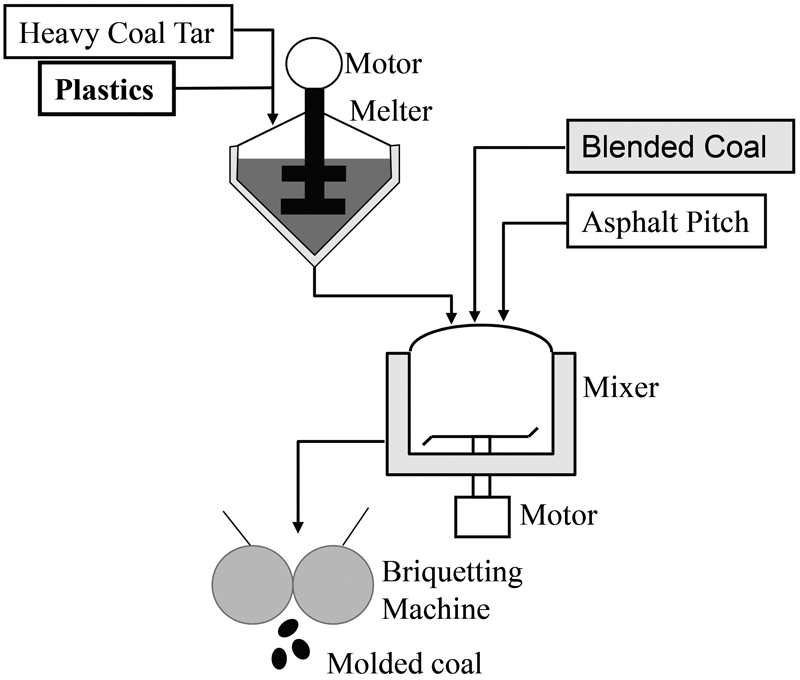
JOURNAL OPEN ACCESS FULL-TEXT HTMLMolded coal charging process into coke oven has been used to improve coal charging density. Molded coal charging process can improve coke strength even if the rank of blended coal is low. However, the molded coal is quite expensive because the cost of coal tar binder is high. Thus, we developed a new process that could reduce the amount of tar binder by utilizing used plastics. In this new process, used plastics were charged into heavy tar and dissolved at 200ºC. The resulting binder with plastics could improve the strength of the molded coal, thus, coke was prepared experimentally using molded coal with the new binder.
The drum strength of the molded coal with plastics binder was better than that of coke using conventional molded coke with heavy tar binder.
Used plastics for the binder could reduce CO2 emissions from coke ovens. This new process is one of the suitable ways of recycling used plastics in steel works.
 View full abstractDownload PDF (1664K) Full view HTML
-
Mayuko Kikuzuki, Koutarou Hayashi, Yusuke Tsunemi, Shohei Yabu, Takash ...2020Volume 106Issue 5 Pages 244-253
Published: 2020
Released on J-STAGE: April 30, 2020
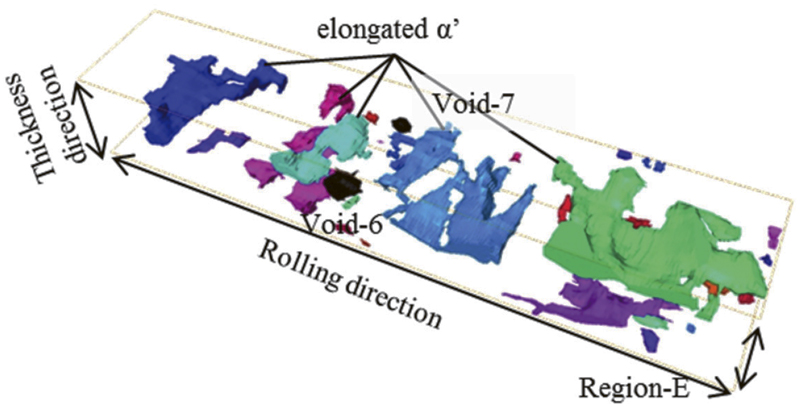
JOURNAL OPEN ACCESS FULL-TEXT HTMLThis research centers on elucidating the relationship between void nucleation sites and the morphology/distribution of the surrounding phase in dual-phase steel during the initial stages of ductile fracture. Characteristic features of voids and surrounding ferrite/martensite grains were observed through a three-dimensional (3D) optical microscope analysis with the aid of serial sectioning. The characterized 3D distribution and morphology of ferrite/martensite surrounding the voids were set as an input for a finite flement (FE) simulation to obtain the hydrostatic pressure and equivalent plastic strain in the ferrite and martensite phases during tensile deformation. Experimental results showed that some of the voids present in the ferrites were surrounded by the flat-shaped martensites, which were elongated along both rolling direction (RD) and transversal direction (TD). These flat-shaped martensites were existed along the tensile direction. The FE simulation showed that the ferrite grains sandwiched between the harder martensites are more susceptible to void nucleation; this is due to the concentration of equivalent plastic strain and hydrostatic pressure in the ferrites during tensile deformation.
 View full abstractDownload PDF (2323K) Full view HTML
-
Takuya Mitsunobu, Kohhei Tokuda, Nobuyuki Shimoda2020Volume 106Issue 5 Pages 254-261
Published: 2020
Released on J-STAGE: April 30, 2020
Advance online publication: January 17, 2020JOURNAL OPEN ACCESS FULL-TEXT HTMLThe present study investigated the microstructure in hot-dip Zn-(11, 22, 30)%Al coating steel sheets in order to clarify their solidification microstructure evolution process. There are two kinds of Zn-Al binary phase diagrams. One includes peritectic reaction but another doesn’t. In the Zn-Al binary phase diagram including peritectic reaction, the peritectic reaction occurs when the Al content is higher than 13%. In fact, the peritectic structure was formed in dendrites of the hot-dip Zn-(22, 30)%Al coating steel sheets, but not in the hot-dip Zn-11%Al coating steel sheets. This indicates that the Zn-Al binary phase diagram including peritectic reaction is suitable for understanding the solidification microstructure evolution of hot-dip Zn-Al alloy coating steel sheets.
 View full abstractDownload PDF (3155K) Full view HTML
-
Yo Tomota, Yan Xu Wang, Takahito Ohmura, Nobuaki Sekido, Stefanus Harj ...2020Volume 106Issue 5 Pages 262-271
Published: 2020
Released on J-STAGE: April 30, 2020
JOURNAL OPEN ACCESS FULL-TEXT HTMLThe phase transformation behavior from austenite upon cooling in a 1.5Mn-1.5Si-0.2C steel was in situ monitored using dilatometry, X-ray and neutron diffractions. The starting temperature of ferrite transformation was in good agreement between dilatometry and neutron diffraction, whereas much higher in X-ray diffraction. Such a discrepancy in transformation temperature is attributed to the change in chemical composition near the surface of a specimen heated to elevated temperatures in a helium gas atmosphere for X-ray diffraction. In situ neutron diffraction enables us to investigate the changes in lattice constants of ferrite and austenite, which are affected by not only thermal contraction but also transformation strains, thermal misfit strains and carbon enrichment in austenite. Pearlite transformation started after carbon enrichment in austenite reached approximately 0.7 mass% and contributed to diffraction line broadening.
 View full abstractDownload PDF (4192K) Full view HTML
 -
Hideo Takizawa, Shohei Kodama2020Volume 106Issue 5 Pages 272-280
Published: 2020
Released on J-STAGE: April 30, 2020
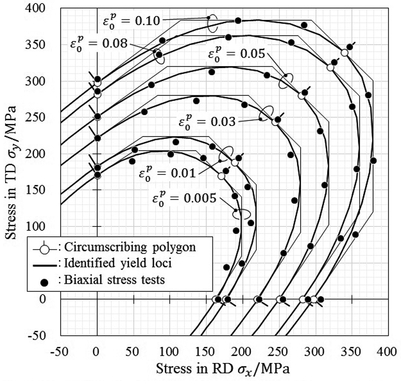
JOURNAL OPEN ACCESS FULL-TEXT HTMLIn this study, a method to identify the yield surface by three types of simplified material tests is proposed. The uniaxial tensile test, hydraulic bulge test, and plane strain tensile test are used in this method. A polygon circumscribing the equal plastic work contour can be defined by assuming the associated flow rule on the direction of the plastic strain rate. The parameters of anisotropic yield function are identified as a smooth curve inscribed in this polygon. This paper describes the details of these material testing methods. The yield surface of the cold-rolled steel sheet (SPCE) is identified by the proposed method and modeled with Yld2000-2d yield function. The model is compared to the stress points which are measured by the biaxial stress tests using cruciform specimen. Both yield loci agree well. Moreover, the yield function identified by the proposed method is applied to two types of simple sheet metal forming problems, the hole expansion test and deep-drawing of cylindrical cup. The results of finite element analysis are compared with the experimental results in both problems. The thickness strain on the hole edge in the hole expansion test and the ear height of the deep-drawn cup are evaluated. The results of the analysis using the modeled yield function agree with the experimental results qualitatively.
 View full abstractDownload PDF (2062K) Full view HTML
-
Yasutaka Ta, Takeru Hoshino, Hiroyuki Tobo, Keiji Watanabe, Katsunori ...2020Volume 106Issue 5 Pages 281-289
Published: 2020
Released on J-STAGE: April 30, 2020
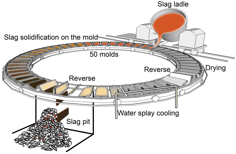
Advance online publication: February 06, 2020JOURNAL OPEN ACCESS FULL-TEXT HTMLA continuous solidification process of blast furnace slag was developed to promote the use of air-cooled slag coarse aggregate for concrete. In this process, the molten slag can solidify in only 120 s and the slag thickness is about 25 mm. This process suppresses gas generation and greatly reduces water absorption. Most of the slag is crystalline, and part of the slag has a glass layer on its surface. Slag with a glass layer is brittle because it contains several cracks. Therefore, microscopic observation and thermal stress analysis of the solidified slag were carried out to clarify the mechanism of crack generation in the plate-like slag. In the microscopic observation, several cracks with a length of about 8 mm were found in the slag with the glass layer. From the analysis, in the cooling pattern of the slag on the piled slag a temperature difference of about 200 K exists between the center and the mold side in the slag pit, and keeping this difference results in tensile stress of more than 50 MPa. However, in the cooling pattern of the crystalline slag in the piled slag, the temperature gradient in the slag in the slag pit was very small because the slag was retained in the piled slag, and as a result, the thermal stress was almost 0 MPa.
 View full abstractDownload PDF (6794K) Full view HTML
- |<
- <
- 1
- >
- >|